Asus 3600 User Guide
Asus 3600 - VENTO Mid Tower Manual
 |
UPC - 610839201853
View all Asus 3600 manuals
Add to My Manuals
Save this manual to your list of manuals |
Asus 3600 manual content summary:
- Asus 3600 | User Guide - Page 1
VENTO 3600 Gaming Machine Chassis Kit User Guide 15-067008400 - Asus 3600 | User Guide - Page 2
Reserved. No part of this manual, including the service will not be extended if: (1) the product is repaired, modified or altered, unless such repair, modification of alteration is authorized in writing by ASUS; or (2) the serial number of the product is defaced or missing. ASUS PROVIDES THIS MANUAL - Asus 3600 | User Guide - Page 3
Safety information v About this guide vi ASUS contact information viii Chapter 1: Product introduction 1.1 Welcome 2 1.2 Package contents 2 1.3 System specification 3 1.4 Exploded drawing 4 1.5 Front panel features 5 1.6 Side panel features 6 1.7 Rear panel features 6 1.8 Internal features - Asus 3600 | User Guide - Page 4
to comply with the limits for a Class B digital device, pursuant to Part 15 of the FCC Rules. These limits are designed to provide reasonable and, if not installed and used in accordance with manufacturer's instructions, may cause harmful interference to radio communications. However, there is - Asus 3600 | User Guide - Page 5
service technician or your retailer. Operation safety • Before installing the motherboard and adding devices on it, carefully read all the manuals area where it may become wet. • Place the product on a stable surface. • If you encounter technical problems with the product, contact a qualified service - Asus 3600 | User Guide - Page 6
guide This user guide contains the general information and installation instructions for the ASUS VENTO 3600 chassis kit. This guide is intended for experienced users and integrators with hardware knowledge of personal computers. How this guide is organized This manual contains the following parts - Asus 3600 | User Guide - Page 7
Conventions To make sure that you perform certain tasks properly, take note of the following symbols used throughout this manual. W A R N I N G : Information to prevent injury to yourself when trying to complete a task. C A U T I O N : Information to prevent damage to the components when trying to - Asus 3600 | User Guide - Page 8
) Address 15 Li-Te Road, Peitou, Taipei, Taiwan 112 Telephone +886-2-2894-3447 Web site www.asus.com.tw Technical Support Telephone (MB/Component) (Notebook) (Server/PC) (Networking) Support fax +886-2-2890-7121 (English) +886-2-2890-7122 (English) +886-2-2890-7123 (English) +886-2-2890-7902 - Asus 3600 | User Guide - Page 9
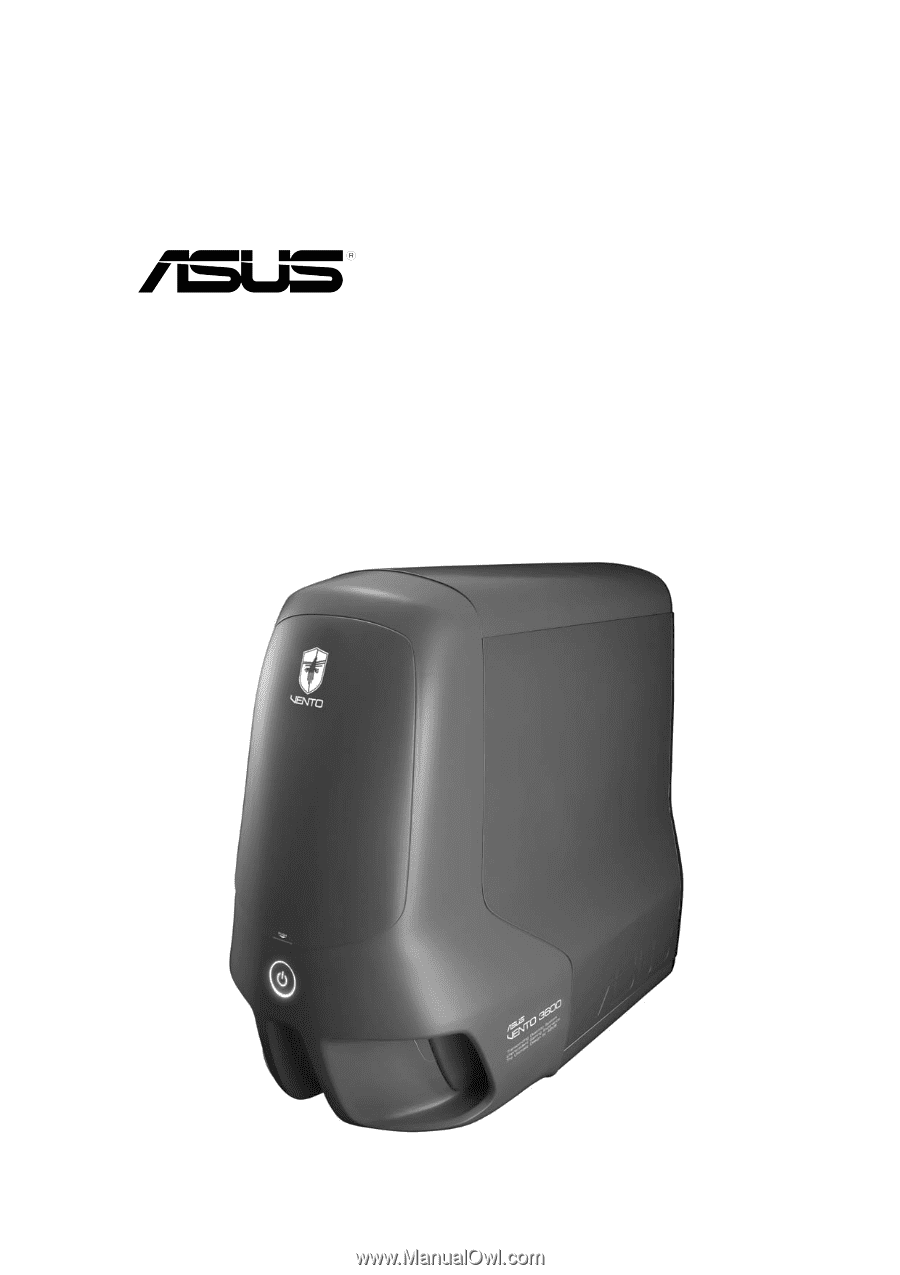
Product introduction Chapter 1 This chapter gives a general description of the ASUS VENTO 3600 chassis kit. The chapter lists the system features and introduces the front and rear panels, and the internal components. ASUS VENTO 3600 - Asus 3600 | User Guide - Page 10
extreme gaming with the ASUS VENTO 3600. 1.2 Package contents Check your ASUS VENTO 3600 for the following items. System fan Accessories Documentation Optional item 1 x 80 mm fan for the front panel 1 x 120 mm system fan for the rear panel 1 x Cable management kit Screws Key lock User guide Power - Asus 3600 | User Guide - Page 11
External 3.5-inch floppy disk drive bays 3 x Internal 3.5-inch hard disk drive bays 6 x PCI 1 x AGP Supports up to 4 USB 2.0 ports 1 x Headphone port 1 x Microphone port ATX form factor: 12" x 9.6" (30.5 cm x 24.4 cm) Green, blue, red 308 (w) x 527 (h) x 627 (d) mm 0.8 mm SECC ASUS VENTO 3600 1-3 - Asus 3600 | User Guide - Page 12
not included) 6. Magic Mask® 7. 5.25" Drive bay covers 8. Side vent for air duct 9. Side panel 10. Side swivel 11. Expansion slot locks 12. Expansion slot covers 13. HDD cage lock 14. Removable HDD cage (drives not included) 15. Expansion slots 16. Chassis feet 17. 80 mm Auxiliary fan 18. Front - Asus 3600 | User Guide - Page 13
the front panel. Flip the Magic Mask® to access the optical drive/s and floppy disk drive/s. Front panel (external) Top panel Magic Mask® Power button USB 2.0 ports Microphone port Headphone port Front panel (internal) 5.25" Drive bay covers 3.5" Floppy disk drive bay cover ASUS VENTO 3600 1-5 - Asus 3600 | User Guide - Page 14
. The side panel also features vent holes with an air duct to pull cool air directly to the components. Side vent for air duct Side swivel Cool LED 1.7 Rear panel features The rear panel includes a slot for the motherboard rear I/O ports, seven full-length expansion slots, chassis cover screw - Asus 3600 | User Guide - Page 15
components as shown. 1 6 2 3 7 4 8 5 9 1. Power supply slot 2. 120 mm system fan vent 3. Motherboard mounting panel 4. Expansion slot covers 5. Chassis intrusion sensor 6. 5.25-inch drive bays 7. 3.5-inch FDD bay 8. Detachable HDD cage 9. 80 mm Auxiliary fan (hidden) ASUS VENTO 3600 1-7 - Asus 3600 | User Guide - Page 16
1-8 Chapter 1: Product introduction - Asus 3600 | User Guide - Page 17
Basic installation Chapter 2 This chapter provides step-by-step instructions on how to install devices and components in the ASUS VENTO 3600. ASUS VENTO 3600 - Asus 3600 | User Guide - Page 18
to the VENTO 3600 chassis kit. 1. Motherboard 2. Power supply unit (PSU) 3. Hard disk drive 4. 5.25-inch drive(s) 5. Floppy disk drive(s) 6. Expansion card(s) Tool You need a Phillips (cross) screw driver to install some system components. 2.2 Removing the side panel To remove the side panel - Asus 3600 | User Guide - Page 19
three screws that secure the left side cover to the chassis. Keep the screw for later use. 4. Turn the side swivel to about 45º clockwise to release the side panel. 5. Push the side panel to the direction of the arrow. 4 5 6. Tilt the side panel, then lift and set aside. ASUS VENTO 3600 2-3 - Asus 3600 | User Guide - Page 20
power supply unit (PSU) We recommend that you install a standard ATX PSU with at least 350 W power output. To install a PSU to the voltage supply in your area. If the voltage supply in your area is 100-127 V, set the switch to 115 V. If the voltage supply in your area is 200-240 V, set the swtich - Asus 3600 | User Guide - Page 21
Installing the motherboard • The VENTO 3600 supports standard ATX and micro ATX (mATX) motherboards. • Refer to the motherboard user guide for detailed instructions on installing a CPU, heatsink and fan assembly, memory, and other components to the motherboard. 1. Lay the chassis down on a stable - Asus 3600 | User Guide - Page 22
the required number of screws with a Phillips screwdriver to secure the motherboard to the chassis. The photo shows the motherboard installed in the chassis. 2.5 Installing a hard disk drive The chassis kit supports two IDE/ Serial ATA hard disk drives through a detachable hard disk drive cage - Asus 3600 | User Guide - Page 23
I D E hard disk drive: 1. Press down the HDD cage lock. 2. Carefully pull the cage out of the chassis in the direction of the arrow. Place the HDD cage on a flat surface. 3. Insert an HDD into the upper the HDD to the cage with two screws on both sides of the cage. Screw holes ASUS VENTO 3600 2-7 - Asus 3600 | User Guide - Page 24
until it snaps to indicate that it is secured to the chassis. 5 6 6. Connect a 40-pin IDE cable to the IDE connector at the back of the drive. 7. Connect a 4-pin power plug from the power supply unit to the power connector at the back of the drive. Refer to the motherboard user guide - Asus 3600 | User Guide - Page 25
. Connect the 15-pin SATA power plug to the power connector at the back of the drive. 15-pin 4-pin (male) Serial ATA power cable ASUS VENTO 3600 2-9 - Asus 3600 | User Guide - Page 26
damage to the motherboard and other system components! The system comes with four 5.25-inch drive bays located on the upper front part of the chassis. 1 2 3 4 2.6.1 Installing an optical drive You may install an optical drive on the uppermost bay. To install an optical drive: 1. Gently push the - Asus 3600 | User Guide - Page 27
Carefully insert the optical drive into the bay, then push it inward until it is completely flushed to the chassis front panel. 5. Align the screw holes as shown. 6. Slide the drive bay lock to the right, towards the you still drive screws into the bay to ensure a firm fit. ASUS VENTO 3600 2-11 - Asus 3600 | User Guide - Page 28
the face plate covering the drive bay by releasing the protruding tabs. 3. Using a screwdriver, push the knock down metal cover in and out of the chassis until it is removed. 4. Slide the drive bay lock to the left, towards the sign, to unlock the drive bay. 2-12 Chapter 2: Basic installation - Asus 3600 | User Guide - Page 29
insert the optical drive into the bay, then push it inward until it is completely flushed to the chassis front panel. 6. Align the screw holes as shown. 7. Slide the drive bay lock to the right, 40-pin IDE cable (from the first optical drive) to the IDE connector on the drive. ASUS VENTO 3600 2-13 - Asus 3600 | User Guide - Page 30
9. Connect a 4-pin power plug from the power supply unit to the drive power connector. 2.7 Installing a 3.5-inch floppy disk drive You may install up to two floppy disk drives in the 3.5-inch drive bay under the 5.25-inch drive bays. Configure your optical drive as Master/Slave device before - Asus 3600 | User Guide - Page 31
metal cover in and out of the chassis until it is removed. 3. Slide the drive bay lock to the right, towards the sign to unlock the drive bay. 4. Carefully insert the floppy disk drive into the bay, then push it inward until it is completely flushed to the chassis front panel. ASUS VENTO 3600 2-15 - Asus 3600 | User Guide - Page 32
5. Slide the drive bay lock to the left, towards the sign to lock the drive bay and to secure the drive in place. The drive bay lock has a screwless design that allows you to secure the floppy disk drive without screws. However, we recommend that you still drive screws into the bay to ensure a firm - Asus 3600 | User Guide - Page 33
2.8 Installing expansion cards The VENTO 3600 chassis kit comes with six PCI slots and one AGP slot for installation of the card. 2. Choose the slot that you want to use. 3. Push out the green lock tab. 4. Remove the metal cover opposite the slot that you want to use. ASUS VENTO 3600 2-17 - Asus 3600 | User Guide - Page 34
5. Align the card connector with the slot, then press firmly until the card is completely seated on the slot. 6. Secure the card with the lock tab you removed earlier. 2-18 Chapter 2: Basic installation - Asus 3600 | User Guide - Page 35
side cover by following these instructions. To replace the side cover: 1. Match the side panel hooks to the chassis rail edge. 2. Fit the side panel toward the chassis until it fits. Chassis side rail 3. Slide the cover toward the front until it snaps in place. Side panel hooks ASUS VENTO 3600 - Asus 3600 | User Guide - Page 36
4. Replace the cable management kit. B C A 2-20 Chapter 2: Basic installation
-
 1
1 -
 2
2 -
 3
3 -
 4
4 -
 5
5 -
 6
6 -
 7
7 -
8
-
9
-
10
-
11
-
12
-
13
-
14
-
15
-
16
-
17
-
18
-
19
-
20
-
21
-
22
-
23
-
24
-
25
-
26
-
27
-
28
-
29
-
30
-
31
-
32
-
33
-
34
-
35
-
36
 |
 |
Gaming Machine Chassis Kit
User Guide
VENTO 3600
15-067008400
15-067008400
15-067008400
15-067008400
15-067008400