Asus A55M-E A55M-E User's Manual
Asus A55M-E Manual
 |
View all Asus A55M-E manuals
Add to My Manuals
Save this manual to your list of manuals |
Asus A55M-E manual content summary:
- Asus A55M-E | A55M-E User's Manual - Page 1
A55M-E Motherboard - Asus A55M-E | A55M-E User's Manual - Page 2
applicable license entitles you to the source code of such software and/or other additional data, you may obtain it for a period of three years after our last shipment of the product, either (1) for free by downloading it from http://support.asus.com/download or (2) for the cost of reproduction and - Asus A55M-E | A55M-E User's Manual - Page 3
you proceed 1-1 1.2 Motherboard overview 1-2 1.3 Accelerated Processing Unit (APU 1-4 1.4 System memory 1-7 1.5 Expansion slots 1-10 1.6 Jumpers...1-12 1.7 Connectors 1-14 1.8 Software support 1-21 Chapter 2: BIOS information 2.1 Managing and updating your BIOS 2-1 2.2 BIOS setup - Asus A55M-E | A55M-E User's Manual - Page 4
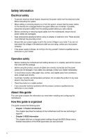
. • If you encounter technical problems with the product, contact a qualified service technician or your retailer. About this guide This user guide contains the information you need when installing and configuring the motherboard. How this guide is organized This guide contains the following parts - Asus A55M-E | A55M-E User's Manual - Page 5
to the following sources for additional information and for product and software updates. 1. ASUS websites The ASUS website provides updated information on ASUS hardware and software products. Refer to the ASUS contact information. 2. Optional documentation Your product package may include optional - Asus A55M-E | A55M-E User's Manual - Page 6
with different models. A55M-E specifications summary APU Chipset Memory Graphics Expansion slots AMD Socket FM2 A-series/Athlon™ Series Processors AMD® Turbo Core Technology 3.0 support Microsoft® DirectX® 11 support • Refer to www.asus.com for the AMD® APU support list. AMD® A55 FCH (Hudson D2 - Asus A55M-E | A55M-E User's Manual - Page 7
Special features Back Panel I/O ports Internal I/O connectors / buttons / switches AMD® A55 FCH: - 4 x Serial ATA 3.0Gb/s connectors support RAID 0, RAID 1, RAID 10 and JBOD configurations Realtek® 8111F PCIe Gigabit LAN controller Realtek® ALC887-VD 8-channel High Definition Audio CODEC • Use - Asus A55M-E | A55M-E User's Manual - Page 8
Support DVD Form factor 32 Mb Flash ROM, UEFI AMI BIOS, PnP, DMI 2.0, WfM 2.0, SM BIOS 2.6, ACPI 2.0a, Multi-language BIOS, ASUS EZ Flash 2, ASUS CrashFreen BIOS 3, F12 Printscreen function, F3 Shortcut function and ASUS DRAM SPD (Serial Presence Detect) memory information Drivers ASUS Update ASUS - Asus A55M-E | A55M-E User's Manual - Page 9
you install motherboard components or change any motherboard settings. • Unplug the power cord from the wall socket before touching motherboard component. The illustration below shows the location of the onboard LED. SB_PWR A55M-E ON OFF Standby Power Powered Off A55M-E Onboard LED ASUS A55M - Asus A55M-E | A55M-E User's Manual - Page 10
or removing the motherboard. Failure to do so can cause you physical injury and damage motherboard components. 1.2.1 Placement direction When installing the motherboard, ensure that indicated by circles to secure the motherboard to the chassis. Do not overtighten the screws! Doing so can damage the - Asus A55M-E | A55M-E User's Manual - Page 11
VGA DVI 11 KBPWR USBPW1-4 SOCKET FM2 USB34 LAN1_USB12 AUDIO RTL 8111F CHA_FAN A55M-E PCIEX16 PCIEX1_1 Lithium Cell CMOS Power ALC887 Super I/O PCI1 SB_PWR SPDIF_OUTCOM1USBPW5-8 USB78 AAFP AMD® A55 SATA3G_1 SATA3G_2 SPEAKER CLRTC USB56 32Mb BIOS SATA3G_3 SATA3G_4 F_PANEL EATXPWR - Asus A55M-E | A55M-E User's Manual - Page 12
1.3 Accelerated Processing Unit (APU) This motherboard comes with an FM2 socket designed for AMD® A-series accelerated processors with AMD® Radeon™ HD 7000/8000 series graphics. A55M-E A55M-E CPU socket FM2 Ensure that you use an APU designed for the FM2 socket. The APU fits in only one correct - Asus A55M-E | A55M-E User's Manual - Page 13
3 4 1.3.2 APU heatsink and fan assembly installation Apply the Thermal Interface Material to the APU heatsink and APU before you install the heatsink and fan if necessary. To install the APU heatsink and fan assembly 1 2 ASUS A55M-E 1-5 - Asus A55M-E | A55M-E User's Manual - Page 14
3 4 5 To uninstall the APU heatsink and fan assembly 1 2 3 4 5 1-6 Chapter 1: Product introduction - Asus A55M-E | A55M-E User's Manual - Page 15
on a DDR2 DIMM socket. DDR3 modules are developed for better performance with less power consumption. The figure illustrates the location of the DDR3 DIMM sockets: DIMM_A1 DIMM_B1 Channel Channel A Channel B Sockets DIMM_A1 DIMM_B1 A55M-E A55M-E 240-pin DDR3 DIMM sockets ASUS A55M-E 1-7 - Asus A55M-E | A55M-E User's Manual - Page 16
a 32-bit Windows® OS. - Use a 64-bit Windows® OS if you want to install 4GB or more memory on the motherboard. • This motherboard does not support DIMMs made up of 512Mb (64MB) chips or less. • The maximum 32GB memory capacity can be supported with 16GB or above DIMMs. ASUS will update the memory - Asus A55M-E | A55M-E User's Manual - Page 17
1.4.3 1 Installing a DIMM 2 3 To remove a DIMM B A ASUS A55M-E 1-9 - Asus A55M-E | A55M-E User's Manual - Page 18
, if any. See Chapter 2 for information on BIOS setup. 2. Assign an IRQ to the card. 3. Install the software drivers for the expansion card. When using PCI cards on shared slots, ensure that the drivers support "Share IRQ" or that the cards do not need IRQ assignments. Otherwise, conflicts will - Asus A55M-E | A55M-E User's Manual - Page 19
supports one PCI Express x16 graphics cards that comply with the PCI Express specifications. IRQ assignments for this motherboard A B C D E F G H PCIEx16_1 - - shared - - - - - PCIEx1_1 shared - - - - - - - PCI1 slot - - - - shared - - - Realtek LAN controller - Asus A55M-E | A55M-E User's Manual - Page 20
process and enter BIOS setup to reenter data. Except when clearing the RTC RAM, never remove the cap on CLRTC jumper default position. Removing the cap will cause system boot failure! • If the steps above do not help, remove the onboard battery and move the jumper again to clear the CMOS RTC RAM - Asus A55M-E | A55M-E User's Manual - Page 21
-8) Set these jumpers to +5V to wake up the computer from S1 sleep mode (CPU stopped, DRAM refreshed, system running in low power mode) using the connected USB devices. and a corresponding setting in the BIOS. A55M-E KBPWR 12 +5V (Default) 23 +5VSB A55M-E Keyboard power setting ASUS A55M-E 1-13 - Asus A55M-E | A55M-E User's Manual - Page 22
ORANGE Linked BLINKING Data activity Speed LED Status Description OFF 10Mbps connection ORANGE 100Mbps connection GREEN 1Gbps connection ACT/LINK SPEED LED LED LAN port 3. Line In port (light blue). This port connects to the tape, CD, DVD player, or other audio sources. 4. Line Out port - Asus A55M-E | A55M-E User's Manual - Page 23
air flow inside the system may damage the motherboard components. These are not jumpers! DO NOT place jumper caps on the fan connectors. • The CPU_FAN connector supports a CPU fan of maximum 2A (24 W) fan power. • Only the CPU_FAN connector support the ASUS Fan Xpert feature. ASUS A55M-E 1-15 - Asus A55M-E | A55M-E User's Manual - Page 24
Power OK GND PIN 1 +5 Volts GND +5 Volts GND +3 Volts +3 Volts PIN 1 A55M-E ATX power connectors GND +5 Volts +5 Volts +5 Volts -5 Volts GND GND GND PSON# Recommended Power Supply Wattage Calculator at http://support.asus. com/PowerSupplyCalculator/PSCalculator.aspx?SLanguage=en-us - Asus A55M-E | A55M-E User's Manual - Page 25
• These connectors are set to AHCI mode by default. If you intend to create a Serial ATA RAID set using these connectors, set the type of the SATA connectors in the BIOS to [RAID]. See section 2.5.2 SATA Configuration for details. • You must install Windows® XP Service Pack 3 or later version before - Asus A55M-E | A55M-E User's Manual - Page 26
pin PANEL) This connector supports several chassis-mounted functions. F_PANEL PWR LED PWR BTN PIN 1 A55M-E HD_LED RESET A55M-E System panel connector • System speaker. The speaker allows you to hear system beeps and warnings. SPEAKER A55M-E PIN 1 A55M-E Speaker Out Connector +5V GND GND Speaker Out - Asus A55M-E | A55M-E User's Manual - Page 27
audio capability. • If you want to connect a high definition front panel audio module to this connector, set the Front Panel Type item in the BIOS to [HD]. See section 2.5.5 Onboard Devices Configuration for details. • The front panel audio I/O module is purchased separately. ASUS A55M-E 1-19 - Asus A55M-E | A55M-E User's Manual - Page 28
supports up to 480Mbps connection speed. USB78 USB56 USB+5V USB_P6USB_P6+ GND NC USB+5V USB_P8USB_P8+ GND NC A55M-E PIN 1 PIN 1 USB+5V USB_P5USB_P5+ GND USB+5V USB_P7USB_P7+ GND A55M-E USB2.0 connectors Never connect a 1394 cable to the USB connectors. Doing so will damage the motherboard - Asus A55M-E | A55M-E User's Manual - Page 29
you install Windows® XP Service Pack 3 or later versions / Windows® Vista Service Pack 1 or later versions before installing the drivers for better compatibility and system stability. 1.8.2 Support DVD information The Support DVD that comes with the motherboard package contains the drivers, software - Asus A55M-E | A55M-E User's Manual - Page 30
update the motherboard BIOS in Windows® environment. • ASUS Update requires an Internet connection either through a network or an Internet Service Provider (ISP). • This utility is available in the support DVD that comes with the motherboard package. Installing ASUS Update To install ASUS Update - Asus A55M-E | A55M-E User's Manual - Page 31
from the Open window, then click Open. 3. Follow the onscreen instructions to complete the updating process. 2.1.2 ASUS EZ Flash 2 The ASUS EZ Flash 2 feature allows you to update the BIOS without using an OS‑based utility. Before you start using this utility, download the latest BIOS file from the - Asus A55M-E | A55M-E User's Manual - Page 32
screen displays may not be same as shown. Before updating BIOS 1. Prepare the motherboard support DVD and a USB flash drive in FAT32/16 format and single partition. 2. Download the latest BIOS file and BIOS Updater from the ASUS website at http://support.asus.com and save them on the USB flash drive - Asus A55M-E | A55M-E User's Manual - Page 33
in DOS environment 1. Insert the USB flash drive with the latest BIOS file and BIOS Updater to the USB port. 2. Boot your computer. When the ASUS Logo appears, press to show the BIOS Boot Device Select Menu. Insert the support DVD into the optical drive and select the optical drive as the - Asus A55M-E | A55M-E User's Manual - Page 34
down or reset the system while updating the BIOS to prevent system boot failure! • For BIOS Updater version 1.30 or later, the utility automatically exits to the DOS prompt after updating BIOS. • Ensure to load the BIOS default settings to ensure system compatibility and stability. Select the Load - Asus A55M-E | A55M-E User's Manual - Page 35
what you see on your screen. • Visit the ASUS website at www.asus.com to download the latest BIOS file for this motherboard. • Ensure that a USB mouse is connected to your motherboard if you want to use the mouse to control the BIOS setup program. • If the system becomes unstable after changing - Asus A55M-E | A55M-E User's Manual - Page 36
of the BIOS setup program Displays the CPU/motherboard temperature, CPU/5V/3.3V/12V voltage output, CPU/chassis fan speed Exits the BIOS setup program without saving the changes, saves the changes and resets the system, or enters the Advanced Mode Selects the boot device priority Displays - Asus A55M-E | A55M-E User's Manual - Page 37
Mode, click Exit, then select ASUS EZ Mode. Back button Menu items Menu bar Configuration fields General help Submenu item Pop-up window Navigation keys Menu bar The menu bar on top of the screen has the following main items: Main Ai Tweaker Advanced Monitor Boot Tool Exit For changing the - Asus A55M-E | A55M-E User's Manual - Page 38
language, and security settings. • If you have forgotten your BIOS password, erase the CMOS Real Time Clock (RTC) RAM to clear the BIOS password. See section 1.7 Jumpers for information on how to section vary depending on the CPU and DIMM model you installed on the motherboard. ASUS A55M-E 2-9 - Asus A55M-E | A55M-E User's Manual - Page 39
Scroll down to display the following items: 2-10 Chapter 2: Getting started - Asus A55M-E | A55M-E User's Manual - Page 40
for the CPU and other system devices. Be cautious when changing the settings of the Advanced menu items. Incorrect field values can cause the system to malfunction. 2.6 Monitor menu The Monitor menu displays the system temperature/power status, and allows you to change the fan settings. ASUS A55M - Asus A55M-E | A55M-E User's Manual - Page 41
2.7 Boot menu The Boot menu items allow you to change the system boot options. Scroll down to display the following items: 2-12 Chapter 2: Getting started - Asus A55M-E | A55M-E User's Manual - Page 42
an item then press to display the submenu. 2.9 Exit menu The Exit menu items allow you to load the optimal default values for the BIOS items, and save or discard your changes to the BIOS items. You can access the EZ Mode from the Exit menu. ASUS A55M-E 2-13 - Asus A55M-E | A55M-E User's Manual - Page 43
, if not installed and used in accordance with manufacturer's instructions, may cause harmful interference to radio communications. However, there use of shielded cables for connection of the monitor to the graphics card is required to assure compliance with FCC regulations. Changes or modifications - Asus A55M-E | A55M-E User's Manual - Page 44
IC: Canadian Compliance Statement Complies with the Canadian ICES-003 Class B specifications. This device complies with RSS 210 of Industry Canada. This Class B device meets all the requirements of the Canadian interference-causing equipment regulations. This device complies with Industry Canada - Asus A55M-E | A55M-E User's Manual - Page 45
products at ASUS REACH website at http://csr.asus.com/english/REACH.htm. DO NOT throw the motherboard in municipal not be placed in municipal waste. ASUS Recycling/Takeback Services ASUS recycling and takeback programs come from asus.com/english/Takeback.htm for detailed recycling information - Asus A55M-E | A55M-E User's Manual - Page 46
, Taipei, Taiwan 11259 Telephone +886-2-2894-3447 Fax +886-2-2890-7798 E-mail [email protected] Web site www.asus.com.tw Technical Support Telephone Online support +86-21-38429911 support.asus.com ASUS COMPUTER INTERNATIONAL (America) Address 800 Corporate Way, Fremont, CA 94539 - Asus A55M-E | A55M-E User's Manual - Page 47
ASUSTeK COMPUTER INC. 4F, No. 150, LI-TE Rd., PEITOU, TAIPEI 112, TAIWAN TAIWAN ASUS COMPUTER GmbH HARKORT STR. 21-23, 40880 RATINGEN GERMANY Product name : Motherboard Model name : A55M-E conform with the essential requirements of the following directives: 2004/108/EC-EMC Directive EN 55022
-
 1
1 -
 2
2 -
 3
3 -
 4
4 -
 5
5 -
 6
6 -
 7
7 -
8
-
9
-
10
-
11
-
12
-
13
-
14
-
15
-
16
-
17
-
18
-
19
-
20
-
21
-
22
-
23
-
24
-
25
-
26
-
27
-
28
-
29
-
30
-
31
-
32
-
33
-
34
-
35
-
36
-
37
-
38
-
39
-
40
-
41
-
42
-
43
-
44
-
45
-
46
-
47
 |
 |

Motherboard
A55M-E