Asus A7V8X A7V8X User Manual
Asus A7V8X Manual
 |
View all Asus A7V8X manuals
Add to My Manuals
Save this manual to your list of manuals |
Asus A7V8X manual content summary:
- Asus A7V8X | A7V8X User Manual - Page 1
Motherboard A7V8X User Guide - Asus A7V8X | A7V8X User Manual - Page 2
express written permission of ASUSTeK COMPUTER INC. ("ASUS"). Product warranty or service will not be extended if: (1) the ASUS HAS BEEN ADVISED OF THE POSSIBILITY OF SUCH DAMAGES ARISING FROM ANY DEFECT OR ERROR IN THIS MANUAL OR PRODUCT. SPECIFICATIONS AND INFORMATION CONTAINED IN THIS MANUAL - Asus A7V8X | A7V8X User Manual - Page 3
used in this guide ix Where to find more information ix ASUS contact information x A7V8X specifications summary xi Chapter 1: Product introduction 1.1 Welcome 1-1 1.2 Package contents 1-1 1.3 Special features 1-2 1.3.1 Product highlights 1-2 1.4 Motherboard overview 1-6 1.4.1 Major - Asus A7V8X | A7V8X User Manual - Page 4
POST Messages 3-2 3.3 Powering off the computer 3-4 Chapter 4: BIOS setup 4.1 Managing and updating your BIOS 4-1 4.1.1 Using ASUS EZ Flash to update the BIOS 4-1 4.1.2 Using AFLASH to update the BIOS 4-3 4.2 BIOS Setup program 4-7 4.2.1 BIOS menu bar 4-8 4.2.2 Legend bar 4-8 4.3 Main Menu - Asus A7V8X | A7V8X User Manual - Page 5
5-32 5.5 Manual Installation of IDE/RAID Drivers 5-34 5.5.1 Win9x-ME Promise® FastTrak376™ Driver 5-34 5.5.2 Win2000 / XP Promise® FastTrak376™ Driver ..... 5-34 5.5.3 Win NT Promise® FastTrak376™ Driver 5-35 5.5.4 Installing the Promise® FastTrak376™ Driver in a New Windows 2000 / XP System - Asus A7V8X | A7V8X User Manual - Page 6
. This equipment generates, uses and can radiate radio frequency energy and, if not installed and used in accordance with manufacturer's instructions, may cause harmful interference to radio communications. However, there is no guarantee that interference will not occur in a particular installation - Asus A7V8X | A7V8X User Manual - Page 7
Contact a qualified service technician or your retailer. Operation safety • Before installing the motherboard and adding devices on it, carefully read all the manuals that came with . • If you encounter technical problems with the product, contact a qualified service technician or your retailer. vii - Asus A7V8X | A7V8X User Manual - Page 8
ASUS A7V8X motherboard. How this guide is organized This manual contains the following parts: • Chapter 1: Product introduction This chapter describes the features of the A7V8X motherboard. It includes brief descriptions of the special attributes of the motherboard and the new technology it supports - Asus A7V8X | A7V8X User Manual - Page 9
in this guide To make sure that you perform certain tasks properly, take note of the following symbols used throughout this manual. DANGER updates. 1. ASUS Websites The ASUS websites worldwide provide updated information on ASUS hardware and software products. The ASUS websites are listed in the ASUS - Asus A7V8X | A7V8X User Manual - Page 10
502-995-0883 Web Site: www.asus.com Support Email: [email protected] ASUS COMPUTER GmbH (Europe) Address: Harkortstr. 25, 40880 Ratingen, BRD, Germany General Fax: +49-2102-442066 General Email: [email protected] (for marketing requests only) Technical Support Support Hotline: MB/Others: +49 - Asus A7V8X | A7V8X User Manual - Page 11
A7V8X specifications summary CPU Chipset Front Side Bus (FSB) Memory Expansion slots IDE Flexible Serial ATA (optional) RAID (optional) Audio (optional) LAN (optional) USB 2.0 IEEE 1394 (optional) Special Features Socket A for AMD Thoroughbred, Athlon XP/Athlon/Duron 600 MHz ~ 2.4 GHz+ Northbridge - Asus A7V8X | A7V8X User Manual - Page 12
(on LAN model only) CPU/Power/Chassis FAN connectors 20 pin ATX power connector IDE LED connector Chassis Intrusion, SM Bus, SIR Smart Card reader connector Front panel audio connector (on audio model only) Game port S/PDIF in/out connector (on audio model only) CD/AUX/Modem audio in (on audio model - Asus A7V8X | A7V8X User Manual - Page 13
Chapter 1 This chapter describes the features of the ASUS A7V8X motherboard. It includes brief explanations of the special attributes of the motherboard and the new technology it supports. Product introduction - Asus A7V8X | A7V8X User Manual - Page 14
Chapter summary 1.1 Welcome 1-1 1.2 Package contents 1-1 1.3 Special features 1-2 1.4 Motherboard overview 1-6 ASUS A7V8X motherboard - Asus A7V8X | A7V8X User Manual - Page 15
with DDR 400 support, the ASUS A7V8X also features AGP 8X, serial ATA, USB 2.0 as well as optional 6-channel audio, Gigabit LAN and 1394. Unique ASUS features such as ASUS C.O.P., Q-Fan and MyLogo2 and more are included to ensure the best user experience and value in a motherboard. Before you start - Asus A7V8X | A7V8X User Manual - Page 16
support only.) Gigabit LAN (optional) The A7V8X with BroadCom Gigabit LAN, delivers transfer speeds up to ten times faster than conventional 10/100 Ethernet connections. Gigabit LAN is the networking standard for the future and is ideal for handling large amounts of data such as video, audio and - Asus A7V8X | A7V8X User Manual - Page 17
you to select the language of your choice from the available options. The localized BIOS menus allow you to configure easier and faster. Visit the ASUS website for information on the supported languages. See page 4-11 on how to select your desired language. ASUS A7V8X motherboard user guide 1-3 - Asus A7V8X | A7V8X User Manual - Page 18
software is now available with ASUS motherboards! Submerge yourself in ahole new multimedia experience. WinDVD: the world's most popular DVD software supporting 5.1-channel audio WinRip: MP3 Player/Encoder/Ripper featuring virtual 5.1-channel and surround sound effects. WinCoder: Real-time MPEG - Asus A7V8X | A7V8X User Manual - Page 19
ASUS A7V8X motherboard user guide 1-5 - Asus A7V8X | A7V8X User Manual - Page 20
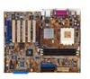
of the A7V8X motherboard as pointed out in the picture on page 1-7. 1. North Bridge controller 2. CPU socket 3. DDR DIMM sockets 4. ATX power connector 5. Floppy disk connector 6. IDE connectors 7. AGP warning LED 8. South Bridge controller 9. ASUS ASIC 10. RAID IDE connector* 11. SATA connectors - Asus A7V8X | A7V8X User Manual - Page 21
12 3 4 21 20 19 18 17 16 15 14 13 22 23 24 31 30 29 28 ASUS A7V8X motherboard user guide 5 6 7 8 9 10 11 12 25 26 27 1-7 - Asus A7V8X | A7V8X User Manual - Page 22
1.4.2 Core specifications 1 North bridge controller. The VIA® KT400 supports AGP 8X mode, 266/200MHz Front Side Bus, and the latest 400/333/266/200MHz 64-bit memory bus. 2 CPU socket. Socket 462 (Socket A) surface mount, Zero Insertion Force (ZIF) socket for the AMD Athlon XP/Athlon/Duron - Asus A7V8X | A7V8X User Manual - Page 23
9 ASUS ASIC. This chip performs multiple system functions that include hardware and system voltage monitoring among others. 10 RAID IDE connector. This one-channel connector supports Ultra ATA133/100/66 hard disk drivers in RAID 0 or RAID 1 configurations. (on SATA model only) 11 SATA connectors. - Asus A7V8X | A7V8X User Manual - Page 24
controller. The BroadCom Gigabit LAN delivers transfer rates up to ten times faster than conventional 10/ 100 Ethernet connections. Ideal for handling large amounts of data such as video, audio and voice. (on LAN models only) 21 AGP slot. This Accelerated Graphics Port (AGP) slot supports 1.5V AGP8X - Asus A7V8X | A7V8X User Manual - Page 25
Chapter 2 This chapter describes the hardware setup procedures that you have to perform when installing system components. It includes details on the switches, jumpers, and connectors on the motherboard. Hardware information - Asus A7V8X | A7V8X User Manual - Page 26
Chapter summary 2.1 Motherboard installation 2-1 2.2 Motherboard layout 2-2 2.3 Before you proceed 2-3 2.4 Central Processing Unit (CPU 2-4 2.5 System memory 2-6 2.6 Expansion slots 2-11 2.7 Switches and jumpers 2-14 2.8 Connectors 2-18 ASUS A7V8X motherboard - Asus A7V8X | A7V8X User Manual - Page 27
in the image below. 2.1.2 Screw holes Place nine (9) screws into the holes indicated by circles to secure the motherboard to the chassis. Do not overtighten the screws! Doing so may damage the motherboard. Place this side towards the rear of the chassis ASUS A7V8X motherboard user guide 2-1 - Asus A7V8X | A7V8X User Manual - Page 28
Firmware Hub PRI_SATA1 CHASSIS1 CHA_FAN1 IDELED1 IEEE1394_1 IEEE1394_2 GAME1 WPCI_USB1 IR_CON1 AFPANEL1 PANEL1 PRI_RAID1 The audio, SATA, Gigabit LAN, LAN and 1394 features are optional. These components are grayed out in the above motherboard layout. 2-2 Chapter 2: Hardware information - Asus A7V8X | A7V8X User Manual - Page 29
AGP slot, this LED lights up thus preventing the system to power up. This LED remains off if you plug in a 1.5V AGP card. AGP_WARN1 ® A7V8X A7V8X Onboard LED ON Incorrect AGP Card OFF Correct AGP Card SB_PWR1 ON Standby Power OFF Powered Off ASUS A7V8X motherboard user guide 2-3 - Asus A7V8X | A7V8X User Manual - Page 30
The motherboard provides a Socket A (462) for CPU installation. AMD processors offer gigahertz speeds to support all the latest computing platforms and applications. The A7V8X supports AthlonTM XP/AthlonTM and DuronTM processors. AMD™ CPU CPU NOTCH TO INNER CORNER ® A7V8X A7V8X Socket A CPU - Asus A7V8X | A7V8X User Manual - Page 31
may occur. When mounting a heatsink onto your CPU, make sure that exposed CPU capacitors do not touch the heatsink, or damage may occur! Do not neglect to set the correct Bus Frequency and leave the CPU Multiple setting at default to avoid start-up problems. ASUS A7V8X motherboard user guide 2-5 - Asus A7V8X | A7V8X User Manual - Page 32
data operations in one clock cycle, thus providing twice the throughput of SDR memory. For example, a 200MHz DDR DIMM will support a 100MHz memory bus, and a 266MHz DDR DIMM will support a 133MHz memory bus. DDR Data Transfer Rate DDR Base Frequency 400MHz 200MHz 333MHz 166MHz 266MHz 133MHz - Asus A7V8X | A7V8X User Manual - Page 33
supports DDR400 modules. Make sure to use only the tested and qualified DDR400 DIMMs listed above. Other DDR DIMMs manufactured by other vendors may not be suitable for this motherboard. Visit the ASUS website (www.asus.com) for the latest qualified vendor DDR400 module list. ASUS A7V8X motherboard - Asus A7V8X | A7V8X User Manual - Page 34
the power supply before adding or removing DIMMs or other system components. Failure to do so may cause severe damage to both the motherboard and the components. Follow these steps to install a DIMM. 1. Unlock a DIMM socket by pressing the retaining clips outward. 2. Align a DIMM on the socket - Asus A7V8X | A7V8X User Manual - Page 35
a DIMM. 1. Simultaneously press the retaining clips outward to unlock the DIMM. Support the DIMM lightly with your fingers when pressing the retaining clips. The DIMM might get damaged when it flips out with extra force. 2. Remove the DIMM from the socket. ASUS A7V8X motherboard user guide 2-9 - Asus A7V8X | A7V8X User Manual - Page 36
2-10 Chapter 2: Hardware information - Asus A7V8X | A7V8X User Manual - Page 37
software settings. 1. Turn on the system and change the necessary BIOS settings, if any. See Chapter 4 for information on BIOS setup. 2. Assign an IRQ to the card. Refer to the tables on the next page. 3. Install the software drivers for the expansion card. ASUS A7V8X motherboard user guide 2-11 - Asus A7V8X | A7V8X User Manual - Page 38
Sound Card (sometimes LPT2) 6 14 Floppy Disk Controller motherboard PCI slot 1 PCI slot 2 PCI slot 3 PCI slot 4 PCI slot 5 PCI slot 6 AGP slot USB 1.1 UHCI 1 USB 1.1 UHCI 2 USB 1.1 UHCI 3 USB 2.0 EHCI AC97 Codec Onboard LAN Onboard 1394 Onboard SATA Onboard IDE that the drivers support "Share IRQ - Asus A7V8X | A7V8X User Manual - Page 39
There are six 32-bit PCI slots in this motherboard. The slots support PCI cards such as a LAN card, SCSI card, USB card, and other cards that comply with PCI specifications. The following figure shows a LAN card installed on a PCI slot. The ASUS BlueMagic PCI slot works as a normal PCI slot and - Asus A7V8X | A7V8X User Manual - Page 40
on the +5VSB lead, and a corresponding setting in the BIOS (see section 4.5.1 Power Up Control). KBPWR1 12 23 +5V +5VSB ® A7V8X (Default) A7V8X Keyboard Power Setting 2. VCORE over-voltage (3-pin OVER_VOLT1) When enabled, this jumper allows CPU VCORE ranges of 1.7V to 2.05V. When this jumper - Asus A7V8X | A7V8X User Manual - Page 41
up from S3 sleep mode (no power to CPU, DRAM in slow refresh, power supply in computers have the appropriate power supply to support this feature. The USBPWR_12 and USBPWR_34 jumpers A7V8X USBPWR_56 12 23 +5V A7V8X USB Device Wake Up (Default) +5VSB ASUS A7V8X motherboard user guide 2-15 - Asus A7V8X | A7V8X User Manual - Page 42
in CMOS. You can clear the CMOS memory of date, time, and system setup enter BIOS setup to re-enter data. ® A7V8X A7V8X Clear RTC RAM CLRTC1 12 23 Clear CMOS Normal (Default) 5. WPCI_USB Setting (6-pin WPCI_USB1) This jumper connects one set of USB signal to PCI slot 6 to support ASUS - Asus A7V8X | A7V8X User Manual - Page 43
the other end to the floppy drive. (Pin 5 is removed to prevent incorrect insertion when using ribbon cables with pin 5 plug). FLOPPY1 ® A7V8X PIN 1 NOTE: Orient the red markings on the floppy ribbon cable to PIN 1. A7V8X Floppy Disk Drive Connector ASUS A7V8X motherboard user guide 2-17 - Asus A7V8X | A7V8X User Manual - Page 44
/133/100/66 devices to the secondary IDE connector. If you install two hard disks, you must configure the second drive as a slave device by setting its jumper accordingly. Refer to the hard disk documentation for the jumper settings. BIOS supports specific device bootup. If you have more than - Asus A7V8X | A7V8X User Manual - Page 45
does not support ATAPI devices such as CD-ROMs, DVD-ROMs, etc. 3. For RAID 1, you may choose any two connectors of Parallel ATA and Serial ATA connectors. For RAID 0, you may choose any two or three connectors of Parallel ATA and Serial ATA connectors. ASUS A7V8X motherboard user guide 2-19 - Asus A7V8X | A7V8X User Manual - Page 46
using the SMBus interface. SMBus is a specific implementation of an I2C bus, a multi-device bus that allows multiple chips to connect to the same bus and enable each one to act as a master by initiating data transfer. SMB_CON1 ® A7V8X 1 A7V8X SMBus Connector FLOATING SMBCLK Ground SMBDATA +3V - Asus A7V8X | A7V8X User Manual - Page 47
you to conveniently make transactions such as financial, health care, telephony, or traveling services through a Smart Card user interface software. SMARTCARD1 ® A7V8X 1 A7V8X Smartcard Connector ASUS A7V8X motherboard user guide VCC NC SCPWR# SCRCLK NC GND NC2 NC NC SCRREST NC SCIO SCRRES# 2-21 - Asus A7V8X | A7V8X User Manual - Page 48
CPU, Chassis, and Power Fan Connectors (3-pin CPU_FAN1, PWR_FAN1, CHA_FAN1) The fan connectors support cooling fans of 350mA~740mA (8.88W max.) or a total of 1A~2.22A (26.64W max.) at +12V. Connect the fan cables to the fan connectors on the motherboard ® A7V8X CHA_FAN1 GND +12V Rotation A7V8X 12 - Asus A7V8X | A7V8X User Manual - Page 49
additional USB ports. The USB header complies with USB 2.0 specification that supports up to 480 Mbps connection speed. This speed advantage over or editing audio files. +5V J1B2 J1CY GND GND J1CX J1B1 +5V ® A7V8X A7V8X Game Connector GAM1 ASUS A7V8X motherboard user guide MIDI_IN J2B2 - Asus A7V8X | A7V8X User Manual - Page 50
Channel Ground Ground Left Audio Channel MODEM1 Modem-In Ground ® A7V8X Ground Modem-Out A7V8X Internal Audio Connectors AUX1(White) CD1(Black) 14. ASUS iPanel connector (24-1 pin AFPANEL1) This connector allows you to connect an optional ASUS iPanel, an easy-to-access drive bay with front - Asus A7V8X | A7V8X User Manual - Page 51
connect to the white IEEE 1394 connector (IEEE1394_2) on-board. +12V Ground TPBTPB+ TPATPA+ Ground Ground +12V Ground TPBTPB+ TPATPA+ Ground Ground blue IEEE1394 connector ® A7V8X IEEE1394_1 A7V8X IEEE-1394 Connectors IEEE1394_2 blue IEEE 1394 connector ASUS A7V8X motherboard user guide 2-25 - Asus A7V8X | A7V8X User Manual - Page 52
allows digital instead of analog sound output. Connect one end of the audio cable to the S/PDIF In/Out connector on the motherboard, and the other end to the S/PDIF module. SPDIF1 ® A7V8X SPDIF_IN +5V SPDIF_OUT GND GND 1 A7V8X Digital Audio Connector 17. Front panel audio connector (10-1 pin - Asus A7V8X | A7V8X User Manual - Page 53
a ribbon cable from the module to the motherboard SIR connector according to the pin definitions. ® A7V8X A7V8X Infrared Module Connector IRTX GND CIRRX CIR+5V +5V IRRX GND IRTX Standard Infrared (SIR) Front View Back View SIR IRTX +5V GND (NC) IRRX ASUS A7V8X motherboard user guide 2-27 - Asus A7V8X | A7V8X User Manual - Page 54
ExtSMI# Ground PWR Ground Reset Ground ® A7V8X A7V8X System Panel Connectors Reset SW SMI Lead beeps and warnings. • System Management Interrupt Lead (2-pin SMI) This 2-pin connector allows you to manually or ON and SOFT OFF, depending on the BIOS or OS settings. Pressing the power switch while - Asus A7V8X | A7V8X User Manual - Page 55
Chapter 3 This chapter describes the power up sequence and gives information on the BIOS beep codes. Powering up - Asus A7V8X | A7V8X User Manual - Page 56
Chapter summary 3.1 Starting up for the first time 3-1 3.2 Vocal POST Messages 3-2 3.3 Powering off the computer 3-4 ASUS A7V8X motherboard - Asus A7V8X | A7V8X User Manual - Page 57
; System running at a lower frequency You will not hear the BIOS beeps when the ASUS POST Reporter™ is enabled. You will hear the vocal POST messages instead. 7. At power on, hold down to enter BIOS Setup. Follow the instructions in Chapter 4. ASUS A7V8X motherboard user guide 3-1 - Asus A7V8X | A7V8X User Manual - Page 58
This motherboard includes the Winbond speech controller to support a special feature called the ASUS POST Reporter™. This feature gives you vocal POST messages and alerts to inform you of system events and boot status. In case of a boot failure, you will hear the specific cause of the problem - Asus A7V8X | A7V8X User Manual - Page 59
disk detected • Make sure you have connected an IDE hard disk drive to the one of the IDE connectors on the motherboard. • See section "2.8 Connectors." CPU temperature too high • Check CPU fan if working properly. CPU fan failed • Check the CPU fan and make sure it turns on after you applied - Asus A7V8X | A7V8X User Manual - Page 60
the power. For ATX power supplies, you can press the ATX power switch after exiting or shutting down the operating system. If you use Windows 95/98/2000/XP, click the Start button, click Shut Down, then click the OK button to shut down the computer. The power supply should turn off - Asus A7V8X | A7V8X User Manual - Page 61
Chapter 4 This chapter tells how to change system settings through the BIOS Setup menus. Detailed descriptions of the BIOS parameters are also provided. BIOS setup - Asus A7V8X | A7V8X User Manual - Page 62
Chapter summary 4.1 Managing and updating your BIOS 4-1 4.2 BIOS Setup program 4-7 4.3 Main Menu 4-10 4.4 Advanced Menu 4-17 4.5 Power Menu 4-27 4.6 Boot Menu 4-33 4.7 Exit Menu 4-35 ASUS A7V8X motherboard - Asus A7V8X | A7V8X User Manual - Page 63
What you see on your screen may not be exactly the same as shown. 4. Insert the disk that contains the new BIOS file into the floppy drive. You will receive the error message, "WARNING! Device not ready." if you proceed to step 5 without the disk in the drive. ASUS A7V8X motherboard user guide 4-1 - Asus A7V8X | A7V8X User Manual - Page 64
name that you downloaded from the ASUS website, then press . EZ Flash will automatically access drive A to look for the file name that you typed. When found, the following message appears on screen. [BIOS Information in File] BIOS Version: A7V8X Boot Block WARNING! Continue to update the BIOS - Asus A7V8X | A7V8X User Manual - Page 65
. 4. In DOS mode, type A:\AFLASH to run AFLASH. If the word "unknown" appears after Flash Memory:, the memory chip is either not programmable or is not supported by the ACPI BIOS and therefore, cannot be programmed by the Flash Memory Writer utility. ASUS A7V8X motherboard user guide 4-3 - Asus A7V8X | A7V8X User Manual - Page 66
5. Select 1. Save Current BIOS to File from the Main menu and press . The Save Current BIOS To File screen appears. 6. Type a filename and the path, for example, A:\XXX-XX.XXX, then press . 4-4 Chapter 4: BIOS Setup - Asus A7V8X | A7V8X User Manual - Page 67
BIOS Including Boot Block and ESCD screen appears. 5. Type the filename of your new BIOS and the path, for example, A:\XXX-XX.XXX, then press . To cancel this operation, press . 6. When prompted to confirm the BIOS update, press Y to start the update. ASUS A7V8X motherboard user guide - Asus A7V8X | A7V8X User Manual - Page 68
process, and if the problem persists, load the original BIOS file you saved to the boot disk. If the Flash Memory Writer utility is not able to successfully update a complete BIOS file, the system may not boot. If this happens, call the ASUS service center for support. 4-6 Chapter 4: BIOS Setup - Asus A7V8X | A7V8X User Manual - Page 69
sub-menus and make your selections among the predetermined choices. Because the BIOS software is constantly being updated, the following BIOS setup screens and descriptions are for reference purposes only, and may not exactly match what you see on your screen. ASUS A7V8X motherboard user guide 4-7 - Asus A7V8X | A7V8X User Manual - Page 70
or Displays the General Help screen from anywhere in the BIOS Setup Jumps to the Exit menu or returns to the main menu plus key) or spacebar Scrolls forward through the values for the highlighted field Brings up a selection menu for the highlighted field or - Asus A7V8X | A7V8X User Manual - Page 71
Item Specific Help window, the BIOS go to the last page. To exit the help window, press or . Sub-menu Note that a right Specific Help window located to the right of each menu. This window displays the help text for the currently highlighted field. ASUS A7V8X motherboard user guide - Asus A7V8X | A7V8X User Manual - Page 72
4.3 Main Menu When you enter the Setup program, the following screen appears. 720K , 3.5 in.] [1.44M, 3.5 in.] [2.88M, 3.5 in.] Floppy 3 Mode Support [Disabled] This is required to support older Japanese floppy drives. The Floppy 3 Mode feature allows reading and writing of 1.2MB (as opposed to 1. - Asus A7V8X | A7V8X User Manual - Page 73
anyone can access the BIOS Setup program. If you did, the Supervisor password is required to enter the BIOS Setup program and to gain Memory [XXX MB] This field automatically displays the amount of conventional memory detected by the system during the boot process. ASUS A7V8X motherboard user guide - Asus A7V8X | A7V8X User Manual - Page 74
to manually enter the IDE hard disk drive parameters. Refer to the next section for details. Before attempting to configure a hard disk drive, make sure you have the correct configuration information supplied by the drive manufacturer. Incorrect settings may cause the system to fail to recognize the - Asus A7V8X | A7V8X User Manual - Page 75
Manually enter the number of cylinders, heads and sectors per track for the drive. Refer to the drive documentation or on the drive label for this information. After entering the IDE hard disk drive information into BIOS, use a disk utility, such as FDISK, to partition and format new IDE hard disk - Asus A7V8X | A7V8X User Manual - Page 76
field to [Manual]. CHS Capacity This field shows the drive's maximum CHS capacity as calculated by the BIOS based on the drive information you entered. Maximum LBA Capacity This field shows the drive's maximum LBA capacity as calculated by the BIOS based on the drive information you entered. 4-14 - Asus A7V8X | A7V8X User Manual - Page 77
allows improved transfer speeds and data integrity for compatible IDE devices. Set to [Disabled] to suppress Ultra DMA capability. To make changes to this field, set the Type field to [User Type HDD]. Configuration options: [0] [1] [2] [3] [4] [5] [Disabled] ASUS A7V8X motherboard user guide 4-15 - Asus A7V8X | A7V8X User Manual - Page 78
upon system boot. Configuration options: [Off] [On] Keyboard Auto-Repeat Rate [6/Sec] This controls the speed at which the system registers repeated keystrokes. Options range from 6 to 30 characters characters. Configuration options: [1/4 Sec] [1/2 Sec] [3/4 Sec] [1 Sec] 4-16 Chapter 4: BIOS Setup - Asus A7V8X | A7V8X User Manual - Page 79
to hang or crash. System memory can only operate at a frequency higher than or equal to the CPU front side bus frequency. Refer to Table 1.4.2 "FSB/DDR Support Table" on page 1-8 for more information. CPU Frequency Multiple (when CPU Speed is set to [Manual]) This field sets the frequency multiple - Asus A7V8X | A7V8X User Manual - Page 80
External Frequency (MHz) (when CPU Speed is set to [Manual]) This feature tells the clock generator what frequency to send to the system bus and PCI bus. The bus frequency (external frequency) multiplied by the bus multiple equals the CPU speed. Memory Frequency (Mhz) [Auto] This field allows you - Asus A7V8X | A7V8X User Manual - Page 81
] [Auto] OS/2 Onboard Memory > 64M [Disabled] When using OS/2 operating systems with installed DRAM of greater than 64MB, you need to set this option to [Enabled]. Otherwise, leave to the default setting [Disabled]. Configuration options: [Disabled] [Enabled] ASUS A7V8X motherboard user guide 4-19 - Asus A7V8X | A7V8X User Manual - Page 82
memory type, size, speed, voltage interface, and module banks. Configuration options: [User Defined] [By SPD] The SDRAM parameters (items 2~5) become configurable only when you set the SDRAM Configuration to [User Defined]. SDRAM CAS Latency (value depends on SDRAM SPD) This item controls controls - Asus A7V8X | A7V8X User Manual - Page 83
AGP Drive P Control [F] Configuration options: [0][1][2][3][4][5][6][7][8][9][A][B][C][D][E][F] AGP performance control [Disabled] Configuration options: [Disabled] [Enabled] AGP Fast Write control [Disabled] Configuration options: [Disabled] [Enabled] ASUS A7V8X motherboard user guide 4-21 - Asus A7V8X | A7V8X User Manual - Page 84
IDE channel or secondary IDE channel, or both. You can also set both channels to [Disabled]. Configuration options: [Both] [Primary] [Secondary] [Disabled] DRAM Burst Length Configuration options: [4] [Auto] S2K Bus Driving Strength Configuration options: [Auto] [Manual] S2K Strobe P Control - Asus A7V8X | A7V8X User Manual - Page 85
Swap A & B These fields set option to switch drive letter assignments. Configuration Options: [No Swap] [Swap AB] Floppy Disk Access Control [R/W] When set to [Read Only], this parameter assign UART2. Configuration options: [COM Port] [IR] [Smart Card Reader] ASUS A7V8X motherboard user guide 4-23 - Asus A7V8X | A7V8X User Manual - Page 86
options: [1] [3] Onboard AC97 Audio Controller [Auto] These fields allow you to enable or disable the onboard AC97 audio controller.Configuration options: [Auto] [ Speech POST Reporter [Enabled] This field enables or disables the ASUS POST Reporter™ feature. See section "1.3 Special Features" and - Asus A7V8X | A7V8X User Manual - Page 87
accelerators or MPEG video cards, may not show colors properly. Setting this field to [Enabled] corrects this problem. If you are BIOS [PCI VGA Card] This field allows you to select the primary graphics card. Configuration options: [PCI VGA Card] [AGP VGA Card] ASUS A7V8X motherboard user guide - Asus A7V8X | A7V8X User Manual - Page 88
Boot ROM This field allows you to enable or disable the onboard LAN Boot ROM. Configuration options: [Disabled] [Enabled] Onboard ATA device First [No] This field allows you to select the a unique IRQ and you are NOT using ICU. Configuration options: [No/ICU] [Yes] 4-26 Chapter 4: BIOS Setup - Asus A7V8X | A7V8X User Manual - Page 89
the period of inactivity before the system enters suspend mode. Refer to "Suspend Mode" Video Off Option [Suspend -> Off ] This field determines when to activate the video off feature for monitor power management. Configuration options: [Always On] [Suspend -> Off] ASUS A7V8X motherboard user guide - Asus A7V8X | A7V8X User Manual - Page 90
Power Management System (DPMS) feature allows the BIOS to control the video display card if it supports the DPMS feature. [Blank Screen] only blanks OFF] [DPMS Reduce ON] HDD Power Down [Disabled] Shuts down any IDE hard disk drives in the system after a period of inactivity as set in this user- - Asus A7V8X | A7V8X User Manual - Page 91
4.5.1 Power Up Control AC PWR Loss Restart [Disabled] This allows you to set whether or not to reboot the system after power interruptions. [ modem off and then back on while the computer is off causes an initialization string that turns the system power on. ASUS A7V8X motherboard user guide 4-29 - Asus A7V8X | A7V8X User Manual - Page 92
Space Bar] This parameter allows you to use specific keys on the keyboard to turn on the set to [Enabled], this parameter allows you to turn on the system through a PCI LAN or modem card. This feature requires an ATX power supply that provides at least 1A ] [By Date] 4-30 Chapter 4: BIOS Setup - Asus A7V8X | A7V8X User Manual - Page 93
Power Fan Speed [xxxxRPM] or [N/A] The onboard hardware monitor automatically detects and displays the CPU, chassis, and power fan speeds in rotations per minute (RPM). If any of the fans is not connected to the motherboard, the specific field shows N/A. ASUS A7V8X motherboard user guide 4-31 - Asus A7V8X | A7V8X User Manual - Page 94
Control [Disabled] This item allows you to enable or disable the ASUS . This item appears only when the Q-Fan Control item is set to [Enabled]. Configuration options: This item appears only when the Q-Fan Control item is set to [Enabled]. Configuration Enter Power setup menu for details". You will then - Asus A7V8X | A7V8X User Manual - Page 95
CD-ROM drive to use in the boot sequence. Pressing [Enter] will show the product IDs of all your connected ATAPI CD-ROM drives. Other Boot Device Select [INT18 Device (Network)] Configuration options: [Disabled] [SCSI Boot Device] [INT18 Device (Network)] ASUS A7V8X motherboard user guide 4-33 - Asus A7V8X | A7V8X User Manual - Page 96
PnP) operating system to configure the PCI bus slots instead of using the BIOS. When [Yes] is selected, interrupts enabled, the BIOS will seek the floppy disk drive to determine whether the drive has 40 the ASUS MyLogo2™ feature. Interrupt Mode [APIC] The Advanced Programmable Interrupt Controller - Asus A7V8X | A7V8X User Manual - Page 97
off. When you select this option, a confirmation window appears. Select [Yes] to save changes and exit want to save your changes before exiting. Pressing saves the changes while exiting. Exit Discarding BIOS asks for a confirmation before exiting. ASUS A7V8X motherboard user guide 4-35 - Asus A7V8X | A7V8X User Manual - Page 98
the Setup menus. When you select this option or if you press , a confirmation window appears. Select [Yes] to load default values. Select Exit Saving Changes or make other After you select this option, a confirmation window appears. Select [Yes] to save any changes to the non-volatile RAM. - Asus A7V8X | A7V8X User Manual - Page 99
Chapter 5 This chapter describes the contents of the support CD that comes with the motherboard package. Software support - Asus A7V8X | A7V8X User Manual - Page 100
Chapter summary 5.1 Install an operating system 5-1 5.2 Support CD information 5-1 5.3 Software information 5-9 5.4 Using the Promise Chip for RAID 0 or 1 .... 5-26 5.5 Manual Installation of IDE/RAID drivers .... 5-34 ASUS A7V8X motherboard - Asus A7V8X | A7V8X User Manual - Page 101
and several utility drivers that enhance the motherboard features. The contents of the support CD are subject to change at any time without notice. Visit the ASUS website for updates. 5.2.1 Running the support CD To begin using the support CD, simply insert the CD into your CD-ROM drive. The CD - Asus A7V8X | A7V8X User Manual - Page 102
Audio Driver Applicaton This item installs the Avance AC'97 compliant audio controller and application. Promise FastTrak 376 Controller Driver This item shows the detailed information installation of the Promise FastTrak 376 controller driver for the Serial ATA and RAID features.. BroadCom 5702 LAN - Asus A7V8X | A7V8X User Manual - Page 103
tab. Click on the Device Manager button to display the Device Manager window. 3. On the Device Manager window, click the plus sign (+) opposite the Network adapters item to show the ASUSTeK/BroadCom 440x 10/100 Integrated Controller. Double-click the item. ASUS A7V8X motherboard user guide 5-3 - Asus A7V8X | A7V8X User Manual - Page 104
4. On the window that appears, click the item Wake Up Capabilities under If the BCM4401 LAN controller is onboard, the Wake-On-LAN feature does NOT work on DOS mode. USB 2.0 Driver This item installs the USB 2.0 driver to upgrade your USB 1.1 ports to USB 2.0. 5-4 Chapter 5: Software support - Asus A7V8X | A7V8X User Manual - Page 105
and other software that the motherboard supports. Simply click on a specific item then follow the installation wizard to install it. ASUS PC Probe This smart utility monitors the fan speed, CPU temperature, and system voltages, and alerts you on any detected problems. This utility helps you keep - Asus A7V8X | A7V8X User Manual - Page 106
RAID utility for monitoring or performing maintenance to a FastTrak Mirrored (RAID 1) or Striped/Mirrored (RAID 0/1) disk array. Winbond Voice Editor This program is for recording and customizing wave files for the ASUS colors. 5.2.4 ASUS Contact Information Clicking the ASUS Contact Information - Asus A7V8X | A7V8X User Manual - Page 107
support CD. This section shows the pop-up windows that appear when you click the icons. Motherboard Info The window displays the general specifications of the A7V8X motherboard. Browse this CD The window displays the support CD contents in graphical format. ASUS A7V8X motherboard user guide 5-7 - Asus A7V8X | A7V8X User Manual - Page 108
Technical Support Form The window displays the ASUS Technical Support Request Form that you have to fill up when requesting technical support. Filelist The window displays the contents of the support CD and a brief description of each in text format. 5-8 Chapter 5: Software support - Asus A7V8X | A7V8X User Manual - Page 109
on the software applications that the motherboard supports. 5.3.1 ASUS Update The ASUS Update is a utility that allows you to update the motherboard BIOS and drivers. This utility requires an Internet connection either through a network or an Internet Service Provider (ISP). Follow these steps to - Asus A7V8X | A7V8X User Manual - Page 110
4. From the FTP site, select the BIOS version that you wish to download. Click Next. 5. Follow the instructions on the succeeding screens to complete the update process. If you selected the option to update the BIOS from a file, a window pops up prompting you to locate the file. Select the file, - Asus A7V8X | A7V8X User Manual - Page 111
of starting from ASUS Update, you may also launch ASUS MyLogo2 directly from the Windows Start menu to change your BIOS boot logo. After you have modified the BIOS file with the new logo, use the ASUS Update utility to upload the new BIOS into the EEPROM. ASUS A7V8X motherboard user guide 5-11 - Asus A7V8X | A7V8X User Manual - Page 112
utility that lets you review useful information about your computer, such as hard disk space, memory usage, and CPU type, CPU speed, and internal/external frequencies through the DMI Explorer. Starting ASUS PC Probe When ASUS PC Probe starts, a splash screen appears allowing you to select whether to - Asus A7V8X | A7V8X User Manual - Page 113
Using ASUS PC Probe Monitoring Monitor Summary Shows a summary of the items being monitored. Temperature Monitor Shows the PC temperature (for supported processors only). Temperature Warning threshold the threshold level) Voltage Monitor Shows the PC voltages. ASUS A7V8X motherboard user guide 5-13 - Asus A7V8X | A7V8X User Manual - Page 114
disable Smart Fan Control. Smart Fan Control adjusts the fan speed automatically based on the current CPU temperature and predefined threshold. Hard Drives Shows the used and free space of the PC's hard disk drives and the file allocation table or file system used. 5-14 Chapter 5: Software support - Asus A7V8X | A7V8X User Manual - Page 115
pertinent to the PC, such as CPU type, CPU speed, and internal/external frequencies, and memory size. Utility Lets you run programs outside of the ASUS Probe modules. To run a program, click Execute Program. NOTE: This feature is currently unavailable. ASUS A7V8X motherboard user guide 5-15 - Asus A7V8X | A7V8X User Manual - Page 116
Probe icon brings up a menu to open or exit ASUS PC Probe and pause or resume all system monitoring. When the ASUS PC Probe senses a problem with your PC, portions of the ASUS PC Probe icon change to red, the PC speaker beeps, and the ASUS PC Probe monitor appears. 5-16 Chapter 5: Software support - Asus A7V8X | A7V8X User Manual - Page 117
the Windows Start button, activate the 3Deep Control Panel program from the 3Deep Applications group on the Main Program menu. The control panel offers access to the Color Wizard tuning program, a Game Gamma setting and a Tweak slider for brightness adjustment. ASUS A7V8X motherboard user guide - Asus A7V8X | A7V8X User Manual - Page 118
3Deep Color Tuning 1. Select the type of monitor connected to the computer, either CRT or LCD. 2. Follow the instructions to manually adjust the brightness level of the monitor. 3. Select the faintest of the three colors: blue, red, and green. 4. Select the color squares that most closely - Asus A7V8X | A7V8X User Manual - Page 119
appears indicating that the tuning process is complete, click Finish. 7. Click on the Set Up Now button to connect to the Internet. Follow the screen instructions to set up True Internet Color. ASUS A7V8X motherboard user guide 5-19 - Asus A7V8X | A7V8X User Manual - Page 120
to customize the vocal POST messages. Install the software from the software menu in the support CD. See section "5.2.3 Software menu". To avoid conflicts, do not run the Winbond Voice Editor while running the ASUS PC Probe. Follow these steps to use the Winbond Voice Editor. Launching the program - Asus A7V8X | A7V8X User Manual - Page 121
Click on the Load button. a window showing the available languages appears. 2. Select update the EEPROM. 4. Click Yes on the confirmation window that appears. The next time you boot your computer, the POST messages are announced in the language that you selected . ASUS A7V8X motherboard user guide - Asus A7V8X | A7V8X User Manual - Page 122
1Mbit, so make your messages as short as possible. 3. Use a recording software, such as Windows Recorder, to record your messages. 4. Save the messages as wave files (.WAV). It is recommended to display the Add Wave File window. 6. Copy the wave files that you recorded to the database. Close the - Asus A7V8X | A7V8X User Manual - Page 123
event on the Voice Editor screen, then on the Edit button. The Event Sound Editor window appears. 8. Locate and select your wave file for the event then click on files at a lower quality • Skip lesser used events like FDD Detection, IDE HDD Detection, etc. ASUS A7V8X motherboard user guide 5-23 - Asus A7V8X | A7V8X User Manual - Page 124
Feature The RealTek ALC650 6-channel AC'97 Audio Driver and Applications are included in the support CD that came with your motherboard package. Install these programs to enable the multi-channel audio feature. You must use 4 or 6 channel speakers for this setup. Setting the RealTek ALC650 AC'97 - Asus A7V8X | A7V8X User Manual - Page 125
not supported by ALC650, it only supports audio programs package. Connector Settings and Functions Connector Lime Light Blue Pink Headphone/2 Speaker 4-Speaker Line Out/ Front Speaker Out Line Out/ Front Speaker Out Line In Rear Speaker Out Mic In Mic In ASUS A7V8X motherboard user guide - Asus A7V8X | A7V8X User Manual - Page 126
5.4 RAID 0/RAID 1 configurations The motherboard includes the Promise® PDC20376 controller chipset, two Serial ATA interfaces, and a Parallel ATA133 interface to support Redundant Array of Independent Disks (RAID) configuration. This feature supports Ultra ATA/133 drives, and is backward compatible - Asus A7V8X | A7V8X User Manual - Page 127
cables. 4. Connect the power cable to the power connector on each drive. 5. Boot the system and enter the BIOS Setup Utility. 6. Go to the Advanced menu and select PCI Configuration. Make sure that the Onboard SATA/IDE RAID Controller field is set to Enabled, and the Onboard ATA Device First field - Asus A7V8X | A7V8X User Manual - Page 128
with the new hard disks installed and connected to the ATAIDE connectors on the motherboard, the MBFastTrak376™ BIOS displays the following: MBFastTrak376 (tm) BIOS version 1.00 (c)2000-2005 Promise Technology, Inc. All Rights Reserved. No Array defined... Press to enter FastBuild (tm - Asus A7V8X | A7V8X User Manual - Page 129
the RAID 0 array as a single drive unit. 7. Install the RAID driver from the support CD that came with the motherboard package. Depending on the operating system you are installing, you may need to install the RAID driver during or after the OS installation. ASUS A7V8X motherboard user guide 5-29 - Asus A7V8X | A7V8X User Manual - Page 130
5.4.4 Creating a RAID 1 array (Security) Creating a Security Array with New Drives 1. In the FastBuild™ utility main menu, press "1" to select Auto key to reboot the system. During the boot process, the MBFastTrak376 BIOS checks and displays the disk array information. 5-30 Chapter 5: Software - Asus A7V8X | A7V8X User Manual - Page 131
utility and follow the format procedure for installing a new hard drive. After you have formatted the arrayed drives, install an operating system (OS). 8. Install the RAID driver from the support CD that came with the motherboard package. Depending on the operating system you are installing, you - Asus A7V8X | A7V8X User Manual - Page 132
11. Install the RAID driver from the support CD that came with the motherboard package. Depending on This command allows you to view the drive assignments of hard disks in an array. Delete Array hard disk. 4. Power off the system and replace the hard disk with an identical model. 5. Reboot and enter - Asus A7V8X | A7V8X User Manual - Page 133
the copy progress for the duration of the task. 9. After the rebuild processis complete, the user is prompted to reboot the system. Controller Configuration (6): This command shows the default for Controller Configuration. The default value is [Enabled]. ASUS A7V8X motherboard user guide 5-33 - Asus A7V8X | A7V8X User Manual - Page 134
] page to reinstall driver or select [Driver] page to update the driver. 7. Follow the instruction to insert your Windows CD or ASUS support CD to install the driver. (Driver Location: {CD-ROM driver}:\Promise\Raid0or1\Win9x-ME) 5.5.2 Win2000 / XP Promise® FastTrak376™ Driver 1. Right click "My - Asus A7V8X | A7V8X User Manual - Page 135
a New Windows 2000 / XP System 1. Read ASUS support CD in another PC and click Browse Support CD. 2. Click Driver folder. 3. Click Promise folder. 4. Select the Promise chip used on your motherboard and click on it. 5. For example, we want to use RAID 0 function on A7V8X motherboard under Windows XP - Asus A7V8X | A7V8X User Manual - Page 136
5-36 Chapter 5: Software support - Asus A7V8X | A7V8X User Manual - Page 137
Index This part contains an alphabetical list of the topics found in this document. - Asus A7V8X | A7V8X User Manual - Page 138
ASUS A7V8X motherboard - Asus A7V8X | A7V8X User Manual - Page 139
DDR SDRAM technology 2-6 Boot Device DIMM selection 4-33 installing 2-8 Boot Up NumLock Status 4-16 removing 2-9 Boot Virus Detection 4-34 DIMM sockets 1-8 C Double Data Rate (DDR) memory 1-2, 2-6 Central Processing Unit (CPU) fan connector 2-22 ASUS A7V8X motherboard user guide I-1 - Asus A7V8X | A7V8X User Manual - Page 140
ROM 1-9 Floppy 3 Mode 4-10 Floppy disk access control 4-23 G GigaBit LAN 1-10 H Hard Disk Drives (HDDs) CHS Capacity 4-14 Cylinders 4-14 Heads 4- Legacy Diskette 4-10 M Motherboard major components 1-6 IRQ Table 2-12 layout 2-2 placement 2-1 screws 2-1 Multi-channel Audio 5-24 Multi-sector transfers - Asus A7V8X | A7V8X User Manual - Page 141
Support CD 5-1 ASUS Update 5-9 Drivers menu 5-2 E-Color 3Deep 5-17 Main menu 5-1 motherboard information 5-7 multi-channel audio 5-24 Utilities menu 5-5 Technical Support Form 5-8 Welcome screen 5-1 Suspend Mode 4-28 System Controller North Bridge 1-8 South Bridge 1-8 System Date 4-10 System memory - Asus A7V8X | A7V8X User Manual - Page 142
I-4 Index
-
 1
1 -
 2
2 -
 3
3 -
 4
4 -
 5
5 -
 6
6 -
 7
7 -
8
-
9
-
10
-
11
-
12
-
13
-
14
-
15
-
16
-
17
-
18
-
19
-
20
-
21
-
22
-
23
-
24
-
25
-
26
-
27
-
28
-
29
-
30
-
31
-
32
-
33
-
34
-
35
-
36
-
37
-
38
-
39
-
40
-
41
-
42
-
43
-
44
-
45
-
46
-
47
-
48
-
49
-
50
-
51
-
52
-
53
-
54
-
55
-
56
-
57
-
58
-
59
-
60
-
61
-
62
-
63
-
64
-
65
-
66
-
67
-
68
-
69
-
70
-
71
-
72
-
73
-
74
-
75
-
76
-
77
-
78
-
79
-
80
-
81
-
82
-
83
-
84
-
85
-
86
-
87
-
88
-
89
-
90
-
91
-
92
-
93
-
94
-
95
-
96
-
97
-
98
-
99
-
100
-
101
-
102
-
103
-
104
-
105
-
106
-
107
-
108
-
109
-
110
-
111
-
112
-
113
-
114
-
115
-
116
-
117
-
118
-
119
-
120
-
121
-
122
-
123
-
124
-
125
-
126
-
127
-
128
-
129
-
130
-
131
-
132
-
133
-
134
-
135
-
136
-
137
-
138
-
139
-
140
-
141
-
142
 |
 |

Motherboard
A7V8X
User Guide