Asus A8N-VM-CSM A8N-VM CSM English Manual E2216
Asus A8N-VM-CSM Manual
 |
View all Asus A8N-VM-CSM manuals
Add to My Manuals
Save this manual to your list of manuals |
Asus A8N-VM-CSM manual content summary:
- Asus A8N-VM-CSM | A8N-VM CSM English Manual E2216 - Page 1
A8N-VM CSM Motherboard - Asus A8N-VM-CSM | A8N-VM CSM English Manual E2216 - Page 2
Product warranty or service will not be extended if: (1) the product is repaired, modified or altered, unless such repair, modification of alteration is authorized in writing by ASUS; or (2) the serial number of the product is defaced or missing. ASUS PROVIDES THIS MANUAL "AS IS" WITHOUT WARRANTY - Asus A8N-VM-CSM | A8N-VM CSM English Manual E2216 - Page 3
vii A8N-VM CSM specifications summary viii Chapter 1: Product introduction 1.1 Welcome 1-2 1.2 Package contents 1-2 1.3 Special features 1-2 1.3.1 Product highlights 1-2 1.3.2 Innovative ASUS features 1-5 1.4 Before you proceed 1-6 1.5 Motherboard overview 1-7 1.5.1 Motherboard layout - Asus A8N-VM-CSM | A8N-VM CSM English Manual E2216 - Page 4
2.1.2 ASUS EZ Flash utility 2-3 2.1.3 AFUDOS utility 2-4 2.1.4 ASUS Update utility 2-6 2.2 BIOS setup program 2-9 2.2.1 BIOS menu screen 2-10 2.2.2 Menu bar 2-10 2.2.3 Navigation keys 2-10 2.2.4 Menu items 2-11 2.2.5 Sub-menu items 2-11 2.2.6 Configuration fields 2-11 2.2.7 Pop-up window - Asus A8N-VM-CSM | A8N-VM CSM English Manual E2216 - Page 5
2-36 Chapter 3: Software support 3.1 Installing an operating system 3-2 3.2 Support CD information 3-2 3.2.1 Running the support CD 3-2 3.2.2 Drivers menu 3-3 3.2.3 Utilities menu 3-4 3.2.4 Make Disk menu 3-5 3.2.5 Manual menu 3-6 3.2.6 ASUS Contact information 3-7 3.2.7 Other information - Asus A8N-VM-CSM | A8N-VM CSM English Manual E2216 - Page 6
. This equipment generates, uses and can radiate radio frequency energy and, if not installed and used in accordance with manufacturer's instructions, may cause harmful interference to radio communications. However, there is no guarantee that interference will not occur in a particular installation - Asus A8N-VM-CSM | A8N-VM CSM English Manual E2216 - Page 7
signal cables from the motherboard, ensure that all service technician or your retailer. Operation safety • Before installing the motherboard and adding devices on it, carefully read all the manuals screws, and staples away from connectors, slots, sockets and circuitry. • Avoid dust, humidity, and - Asus A8N-VM-CSM | A8N-VM CSM English Manual E2216 - Page 8
A8N-VM CSM specifications summary CPU Chipset Front Side Bus Memory Expansion slots Graphics Storage High Definition Audio LAN IEEE 1394 Socket 939 for AMD Athlon™ 64FX/Athlon™ 64 X2/ Athlon™ 64 processors Supports AMD Cool 'n' Quiet™ Technology Northbridge: NVIDIA® GeForce™ 6150 GPU Southbridge: - Asus A8N-VM-CSM | A8N-VM CSM English Manual E2216 - Page 9
A8N-VM CSM specifications summary USB Special features Supports up to 8 USB 2.0 ports ASUS Q-Fan ASUS C.P.R. (CPU Parameter Recall) ASUS CrashFree BIOS 2 ASUS EZ Flash ASUS MyLogo2™ Stepless Frequency Selection (SFS) allows FSB tuning from 200 MHz to 240 MHz at 1 MHz increment N o t e : ASUS - Asus A8N-VM-CSM | A8N-VM CSM English Manual E2216 - Page 10
A8N-VM CSM specifications summary Manageability Support CD contents WfM2.0, DMI 2.0, WOL by PME, WOR by PME Device drivers ASUS PC Probe II AMD Cool 'n'Quiet™ utility ASUS Live Update utility Anti-virus software (OEM version) *Specifications are subject to change without notice. x - Asus A8N-VM-CSM | A8N-VM CSM English Manual E2216 - Page 11
This chapter describes the motherboard features and the new technologies it supports. 1Product introduction - Asus A8N-VM-CSM | A8N-VM CSM English Manual E2216 - Page 12
Application CD Documentation ASUS A8N-VM CSM motherboard 2 x Serial ATA signal cables 1 x Serial ATA power cable for two Serial ATA devices 1 x IEEE 1394 1-port module 1 x Ultra DMA 133/100/66 cable 1 x IDE cable 1 x Floppy disk drive cable I/O shield ASUS motherboard support CD User guide If any - Asus A8N-VM-CSM | A8N-VM CSM English Manual E2216 - Page 13
. Serial ATA allows for thinner, more flexible cables with lower pin count, reduced voltage requirement. See page 1-24 for details. The Hot Swap function is supported only in RAID mode. ASUS A8N-VM CSM 1-3 - Asus A8N-VM-CSM | A8N-VM CSM English Manual E2216 - Page 14
S/PDIF digital sound ready The motherboard supports the S/PDIF Out function through the S/PDIF interface at midboard. The S/PDIF technology turns your computer into a high-end entertainment system with digital connectivity to powerful audio and speaker systems. See page 1-25 for details. USB 2.0 - Asus A8N-VM-CSM | A8N-VM CSM English Manual E2216 - Page 15
restores the CPU default setting for each parameter. ASUS CrashFree BIOS 2 This feature allows you to restore the original BIOS data from the support CD in case when the BIOS codes and data are corrupted. This protection eliminates the need to buy a replacement ROM chip. ASUS A8N-VM CSM 1-5 - Asus A8N-VM-CSM | A8N-VM CSM English Manual E2216 - Page 16
precautions before you install motherboard components or change any motherboard settings. • Unplug the power cord from the wall socket before touching any component in any motherboard component. The illustration below shows the location of the onboard LED. A8N-VM CSM ® A8N-VM CSM Onboard LED - Asus A8N-VM-CSM | A8N-VM CSM English Manual E2216 - Page 17
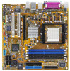
1.5.1 Motherboard layout PS/2KBMS T: Mouse B: Keyboard KBPWR DVI ATX12V 24.5cm (9.6in) CPU_FAN Super I/O EATXPWR A8N-VM CSM DDR DIMM_A2 (64 bit,184-pin module) DDR DIMM_A1 (64 bit,184-pin module) DDR DIMM_B2 (64 bit,184-pin module) DDR DIMM_B1 (64 bit,184-pin module) Socket 939 PARALLEL - Asus A8N-VM-CSM | A8N-VM CSM English Manual E2216 - Page 18
image below. 1.5.3 Screw holes Place eight (8) screws into the holes indicated by circles to secure the motherboard to the chassis. Do not overtighten the screws! Doing so can damage the motherboard. Place this side towards the rear of the chassis ® A8N-VM CSM 1-8 Chapter 1: Product introduction - Asus A8N-VM-CSM | A8N-VM CSM English Manual E2216 - Page 19
socket on the motherboard. A8N-VM CSM ® A8N-VM CSM CPU Socket 939 2. Unlock the socket by pressing the lever sideways, then lift it up to a 90°-100° angle. Socket lever Make sure that the socket lever is lifted up to 90°-100° angle, otherwise the CPU does not fit in completely. ASUS A8N-VM CSM - Asus A8N-VM-CSM | A8N-VM CSM English Manual E2216 - Page 20
down the socket lever to secure the CPU. The lever clicks on the side tab to indicate that it is locked. 6. Install a CPU heatsink and fan following the instructions that came with the heatsink package. 7. Connect the CPU fan cable to the CPU_FAN connector on the motherboard. CPU_FAN A8N-VM CSM GND - Asus A8N-VM-CSM | A8N-VM CSM English Manual E2216 - Page 21
modules from the same vendor. • Due to chipset limitation, this motherboard does not support DIMM modules with less than or equal to 128 Mb memory chips. • If you are installing only one DIMM module for a Single-channel configuration, install the module on DIMM_A1 (blue slot). ASUS A8N-VM CSM 1-11 - Asus A8N-VM-CSM | A8N-VM CSM English Manual E2216 - Page 22
* Use only identical DIMM pairs. Sockets DIMM_A1 (blue) DIMM_B2 (black) Populated - Populated Populated - Populated DIMM_B1 (black) - - Populated Visit the ASUS website (www.asus.com) for the latest DDR 400 Qualified Vendors List for this motherboard. 1-12 Chapter 1: Product introduction - Asus A8N-VM-CSM | A8N-VM CSM English Manual E2216 - Page 23
2 1. Simultaneously press the retaining clips outward to unlock the DIMM. 1 1 DDR DIMM notch Support the DIMM lightly with your fingers when pressing the retaining clips. The DIMM might get damaged when it flips out with extra force. 2. Remove the DIMM from the socket. ASUS A8N-VM CSM 1-13 - Asus A8N-VM-CSM | A8N-VM CSM English Manual E2216 - Page 24
the expansion cards that they support. Make sure to unplug the physical injury and damage motherboard components. 1.8.1 Installing Remove the system unit cover (if your motherboard is already installed in a chassis). 3. the necessary BIOS settings, if any. See Chapter 2 for information on BIOS setup. - Asus A8N-VM-CSM | A8N-VM CSM English Manual E2216 - Page 25
- B - used - C D -- -- - shared When using PCI cards on shared slots, ensure that the drivers support "Share IRQ" or that the cards do not need IRQ assignments; otherwise, conflicts will arise between the two PCI groups, making the system unstable and the card inoperable. ASUS A8N-VM CSM 1-15 - Asus A8N-VM-CSM | A8N-VM CSM English Manual E2216 - Page 26
, SCSI card, USB card, and other cards that comply with PCI specifications. The figure shows a LAN card installed on a PCI slot. 1.8.4 PCI Express x1 slot This motherboard supports PCI Express x1 network cards, SCSI cards and other cards that comply with the PCI Express specifications. The following - Asus A8N-VM-CSM | A8N-VM CSM English Manual E2216 - Page 27
the key during the boot process and enter BIOS setup to re-enter data. Except when clearing the RTC RAM, never remove the cap on CLRTC jumper default position. Removing the cap will cause system boot failure! A8N-VM CSM ® A8N-VM CSM Clear RTC RAM CLRTC 2 1 Normal (Default) 3 2 Clear CMOS - Asus A8N-VM-CSM | A8N-VM CSM English Manual E2216 - Page 28
jumpers to +5V to wake up the computer from S1 sleep mode (CPU stopped, DRAM refreshed, system running in low power mode) using the connected ports. A8N-VM CSM USBPW34 USBPW12 3 3 2 2 2 2 1 1 +5V (Default) +5VSB +5V (Default) +5VSB USBPW78 USBPW56 ® 246 246 A8N-VM CSM USB device - Asus A8N-VM-CSM | A8N-VM CSM English Manual E2216 - Page 29
Space Bar). This feature requires an ATX power supply that can supply at least 500 mA on the +5VSB lead, and a corresponding setting in the BIOS. A8N-VM CSM KBPWR 12 23 +5V (Default) +5VSB ® A8N-VM CSM Keyboard power setting ASUS A8N-VM CSM 1-19 - Asus A8N-VM-CSM | A8N-VM CSM English Manual E2216 - Page 30
1394a port provides high-speed connectivity for audio/video devices, storage peripherals, PCs, or portable devices. 4 . L A N ( R J - 4 5 ) p o r t . This port allows Gigabit connection to a Local Area Network (LAN) through a network hub. LAN port LED indications ACT/LINK LED Status Description - Asus A8N-VM-CSM | A8N-VM CSM English Manual E2216 - Page 31
configuration table for the function of the audio ports in 2, 4, or 6,-channel configuration. Audio 2, 4, or 6-channel configuration Port connects a Digital Visual Interface (DVI) card. 1 2 . P S / 2 k e y b o a r d p o r t ( p u r p l e ) . This port is for a PS/2 keyboard. ASUS A8N-VM CSM 1-21 - Asus A8N-VM-CSM | A8N-VM CSM English Manual E2216 - Page 32
using an FDD cable with a covered Pin 5. FLOPPY NOTE: Orient the red markings on the floppy ribbon cable to PIN 1. ® PIN 1 A8N-VM CSM Floppy disk drive connector 2 . Chassis intrusion connector (4-1 pin CHASSIS) This connector is for a chassis-mounted intrusion detection sensor or switch. Connect - Asus A8N-VM-CSM | A8N-VM CSM English Manual E2216 - Page 33
cable has three connectors: a blue connector for the primary IDE connector on the motherboard, a black connector for an Ultra DMA 133/100/66 IDE slave device for Ultra DMA 133/100/66 IDE devices. A8N-VM CSM SEC_IDE PRI_IDE ® A8N-VM CSM IDE connectors PIN 1 NOTE: Orient the red markings (usually - Asus A8N-VM-CSM | A8N-VM CSM English Manual E2216 - Page 34
RSATA_TXP1 GND A8N-VM CSM SATA connectors SATA1 SATA3 Important note on Serial ATA Install the Windows® 2000 Service Pack 4 or the Windows® XP Service Pack1 before using Serial ATA. For detailed instructions on how to configure RAID 0, 1, 0+1, and 5, refer to the RAID manual in the support CD - Asus A8N-VM-CSM | A8N-VM CSM English Manual E2216 - Page 35
GND +12V Rotation A8N-VM CSM 5. CPU and Chassis fan connectors (3-pin CPU_FAN, 3-pin CHA_FAN) The fan connectors support cooling fans of 350mA~740mA (8.88W max.) or a total of 1A~2.22A (26.64W max.) at +12V. Connect the fan cables to the fan connectors on the motherboard, making sure that the - Asus A8N-VM-CSM | A8N-VM CSM English Manual E2216 - Page 36
Doing so will damage the motherboard! The USB 2.0 module is purchased separately. 8 . Optical drive audio in connector (4-pin CD) These connectors allow you to receive stereo audio input from sound sources such as a CD-ROM, TV tuner, or MPEG card. A8N-VM CSM Left Audio Channel Ground Ground Right - Asus A8N-VM-CSM | A8N-VM CSM English Manual E2216 - Page 37
A8N-VM CSM TPA1GND TPB1+12V GND TPA1+ GND TPB1+ +12V ® IE1394_1 1 A8N-VM CSM IEEE 1394a connector Never connect a U S B p o r t m o d u l e c a b l e to the IEEE 1394a connector. Doing so will damage the motherboard . COM1 PIN 1 ® A8N-VM CSM COM port connector A8N-VM CSM ASUS A8N-VM CSM 1-27 - Asus A8N-VM-CSM | A8N-VM CSM English Manual E2216 - Page 38
NC Line out_L PORT1 L PORT1 R PORT2 R SENSE_SEND PORT2 L A8N-VM CSM Analog front panel connector • We recommend that you connect a high-definition front panel audio module to this connector to avail of the motherboard high-definition audio capability. • If you want to connect a high-definition - Asus A8N-VM-CSM | A8N-VM CSM English Manual E2216 - Page 39
The system may become unstable or may not boot up if the power is inadequate. • You must install a PSU with a higher power rating if you intend to install additional devices. EATXPWR A8N-VM CSM ATX12V ® GND GND +12V DC +12V DC A8N-VM CSM ATX power connectors +3 Volts -12 Volts Ground PSON - Asus A8N-VM-CSM | A8N-VM CSM English Manual E2216 - Page 40
supports several chassis-mounted functions. PLED SPEAKER PANEL ® IDE_LED RESET PWRSW A8N-VM CSM cable to this connector. The IDE LED lights up or flashes when data is read from or written to the HDD in SLEEP or SOFT-OFF mode depending on the BIOS settings. Pressing the power switch for more than four - Asus A8N-VM-CSM | A8N-VM CSM English Manual E2216 - Page 41
This chapter tells how to change the system settings through the BIOS Setup menus. Detailed descriptions of the BIOS parameters are also provided. 2 BIOS setup - Asus A8N-VM-CSM | A8N-VM CSM English Manual E2216 - Page 42
.) ASUS EZ Flash and ASUS CrashFree BIOS 2 only support VGA/RGB output. These utilities do not support VGA/DVI-D output. 3. A S U S U p d a t e (Updates the BIOS in Windows® environment.) Refer to the corresponding sections for details on these utilities. Save a copy of the original motherboard BIOS - Asus A8N-VM-CSM | A8N-VM CSM English Manual E2216 - Page 43
, then follow screen instructions to continue. 2. Copy the original or the latest motherboard BIOS file to the bootable floppy disk. 2.1.2 ASUS EZ Flash utility The ASUS EZ Flash feature allows you to update the BIOS without having to go through the long process of booting from a floppy disk - Asus A8N-VM-CSM | A8N-VM CSM English Manual E2216 - Page 44
to save the file. • The succeeding BIOS screens are for reference only. The actual BIOS screen displays may not be exactly the same as shown. 1. Copy the AFUDOS utility (afudos.exe) from the motherboard support CD to the bootable floppy disk you created earlier. 2. Boot the system in DOS mode, then - Asus A8N-VM-CSM | A8N-VM CSM English Manual E2216 - Page 45
from the hard disk drive. A:\>afudos /iA8NVMCSM.ROM AMI Firmware Update Utility - Version 1.10 Copyright (C) 2002 American Megatrends, Inc. All rights reserved. Reading file ..... done Erasing flash .... done Writing flash .... 0x0008CC00 (9%) Verifying flash .. done A:\> ASUS A8N-VM CSM 2-5 - Asus A8N-VM-CSM | A8N-VM CSM English Manual E2216 - Page 46
the BIOS version information. This utility is available in the support CD that comes with the motherboard package. ASUS Update requires an Internet connection either through a network or an Internet Service Provider (ISP). Installing ASUS Update To install ASUS Update: 1. Place the support CD in - Asus A8N-VM-CSM | A8N-VM CSM English Manual E2216 - Page 47
p d a t e. The ASUS Update main window appears. 2. Select U p d a t e B I O S f r o m 3. Select the ASUS FTP site t h e I n t e r n e t option from the nearest you to avoid network drop-down menu, then click traffic, or click A u t o S e l e c t. N e x t. Click N e x t. ASUS A8N-VM CSM 2-7 - Asus A8N-VM-CSM | A8N-VM CSM English Manual E2216 - Page 48
to download. Click Next. 5. Follow the screen instructions to complete the update process. The ASUS Update utility is capable of updating itself through the Internet. Always update the utility to avail all its features. Updating the BIOS through a BIOS file To update the BIOS through a BIOS file - Asus A8N-VM-CSM | A8N-VM CSM English Manual E2216 - Page 49
the Exit Menu. See section "2.7 Exit Menu." • The BIOS setup screens shown in this section are for reference purposes only, and may not exactly match what you see on your screen. • Visit the ASUS website (www.asus.com) to download the latest BIOS file for this motherboard and . ASUS A8N-VM CSM 2-9 - Asus A8N-VM-CSM | A8N-VM CSM English Manual E2216 - Page 50
2.2.1 BIOS menu screen Menu items Menu bar Configuration fields General help Main Advanced BIOS SETUP UTILITY Power Boot Exit System Time System Date Legacy Diskette A Primary IDE Master Primary IDE Slave Secondary IDE Master Secondary IDE Slave First SATA Second SATA Third SATA - Asus A8N-VM-CSM | A8N-VM CSM English Manual E2216 - Page 51
i n shows the Main menu items. The other items (Advanced, Power, Boot, and Exit) on the menu bar have their respective menu items. 2.2.5 Sub [Disabled] [Enabled] Pop-up window At the top right corner of the menu screen is a brief description of the selected item. Scroll bar ASUS A8N-VM CSM 2-11 - Asus A8N-VM-CSM | A8N-VM CSM English Manual E2216 - Page 52
you an overview of the basic system information. Refer to section "2.2.1 BIOS menu screen" for information on the menu screen items and how to navigate through them. Main Advanced BIOS SETUP UTILITY Power Boot Exit System Time System Date Legacy Diskette A Primary IDE Master Primary IDE - Asus A8N-VM-CSM | A8N-VM CSM English Manual E2216 - Page 53
Transfer [Enabled] Select Screen Select Item +- Change , Inc. The BIOS automatically detects the values supports multi-sector transfer feature. When set to [Disabled], the data transfer from and to the device occurs one sector at a time. Configuration options: [Disabled] [Auto] ASUS A8N-VM CSM - Asus A8N-VM-CSM | A8N-VM CSM English Manual E2216 - Page 54
Sets the Smart Monitoring, Analysis, and Reporting Technology monitoring support. Configuration options: [Auto] [Disabled] [Enabled] 32Bit 4 nVidia RAID Function BIOS SETUP UTILITY [Enabled] [Enabled] [Enabled] [Enabled] [Disabled] Options Enabled Disabled Select Screen Select Item +- Change - Asus A8N-VM-CSM | A8N-VM CSM English Manual E2216 - Page 55
Screen Select Item F1 General Help F10 Save and Exit ESC Exit v02.58 (C)Copyright 1985-2004, American Megatrends, Inc. AMI BIOS Displays the auto-detected BIOS information. Processor Displays the auto-detected CPU specification. System Memory Displays the auto-detected system memory. ASUS A8N-VM - Asus A8N-VM-CSM | A8N-VM CSM English Manual E2216 - Page 56
system to malfunction. Main Advanced BIOS SETUP UTILITY Power Boot Exit AMD Cool 'N' Quiet Configuration JumperFree Configuration CPU Configuration Chipset Onboard Devices Configuration PCI PnP USB Configuration Configure AMD Cool 'N' Quiet support Select Screen Select Item Enter Go to Sub - Asus A8N-VM-CSM | A8N-VM CSM English Manual E2216 - Page 57
by the BIOS. Use the < + > and < - > keys to adjust the CPU FSB frequency. You can also type the desired CPU frequency using the numeric keypad. The values range from 200 to 240. Refer to the table below for the correct Front Side Bus and CPU External Frequency settings. ASUS A8N-VM CSM 2-17 - Asus A8N-VM-CSM | A8N-VM CSM English Manual E2216 - Page 58
the sub-menu. Advanced BIOS SETUP UTILITY Advanced Chipset Settings Options for NB WARNING: Setting wrong values in below sections may cause system to malfunction. NorthBridge Configuration SouthBridge/MCP51 Configuration Hyper Transport Configuration Select Screen Select Item Enter Go to - Asus A8N-VM-CSM | A8N-VM CSM English Manual E2216 - Page 59
Advanced Memory Configuration Memclock Mode MCT Timing Mode User Config Mode Burst Length Software Memory Hole BIOS SETUP UTILITY [Auto] [Auto] [Auto] [4 Beats] [Disabled] MEMCLK can be set by the code using AUTO, or if you use LIMIT, you can set one of the standard values. ASUS A8N-VM CSM 2-19 - Asus A8N-VM-CSM | A8N-VM CSM English Manual E2216 - Page 60
MHz] [133 MHz] [166 MHz] [183 MHz] [200 MHz] MCT Timing Mode [Auto] [Auto] allows the BIOS to set the MCT timing mode automatically. [Manual] allows you to set the values by yourself. Configuration options: [Auto] [Manual] The following items appear when the M C T T i m i n g M o d e item is set to - Asus A8N-VM-CSM | A8N-VM CSM English Manual E2216 - Page 61
Cache BG Scrub BIOS SETUP UTILITY [Enabled] [Disabled] [Disabled] [Disabled] [Disabled] [Disabled] [Disabled] DRAM ECC allows hardware to report and correct memory errors automatically, you to enable or disable ECC chip kill. Configuration options: [Disabled] [Enabled] ASUS A8N-VM CSM 2-21 - Asus A8N-VM-CSM | A8N-VM CSM English Manual E2216 - Page 62
memory errors so later reads are correct. Doing this while memory Data Cache RAM to Chipset Configuration Primary Graphics Adapter OnChip VGA Frame Buffer Size OnChip VGA Trap Enable [[PCI -> PCI Express] [64 MB] [Disabled] Options PCI -> PCI Express -> IGP IGP -> PCI Express -> PCI Select Screen - Asus A8N-VM-CSM | A8N-VM CSM English Manual E2216 - Page 63
IGP] Allows selection of the graphics controller to use as a primary boot device. Configuration options: [PCI -> PCI Express -> IGP] [IGP Enabled] SouthBridge/MCP51 Chipset Configuration Advanced SouthBridge/MCP51 Chipset Configuration PCI Spread Spread] [Down Spread] ASUS A8N-VM CSM 2-23 - Asus A8N-VM-CSM | A8N-VM CSM English Manual E2216 - Page 64
Hyper Transport Configuration Advanced BIOS Setup Utility Hyper Transport C51PV Configuration LDT (K8) to (NB) LinkWidth [800 MHz] [8 8 ] LDT (K8) to C51G (NB)frequency selection. Select Screen Select Item +- Change Option F1 General Help F10 Save and Exit ESC Exit v02.58 (C)Copyright 1985- - Asus A8N-VM-CSM | A8N-VM CSM English Manual E2216 - Page 65
options: [IRQ5] [IRQ7] Onboard AUDIO [Enabled] Allows you to enable or disable the onboard audio controller. Configuration options: [Disabled] [Enabled] Onboard LAN [Enabled] Allows you to enable or disable the onboard LAN. Configuration options: [Disabled] [Enabled] ASUS A8N-VM CSM 2-25 - Asus A8N-VM-CSM | A8N-VM CSM English Manual E2216 - Page 66
Device] [PCI Device] [PCI Device] NO: Lets the BIOS configure all the devices in the system. YES: Lets the operating system configure Plug and Play (PnP) devices not required for boot if your system has a Plug and Play operating system. Select Screen Select Item +- Change Option F1 General Help F10 - Asus A8N-VM-CSM | A8N-VM CSM English Manual E2216 - Page 67
the USB 2.0 controller mode to HiSpeed (480 Mbps) or FullSpeed (12 Mbps). Configuration options: [FullSpeed] [HiSpeed] BIOS EHCI Hand-Off [Enabled] Allows you to enable support for operating systems without an EHCI hand-off feature. Configuration options: [Disabled] [Enabled] ASUS A8N-VM CSM 2-27 - Asus A8N-VM-CSM | A8N-VM CSM English Manual E2216 - Page 68
Select an item then press to display the configuration options. Main Advanced BIOS SETUP UTILITY Power Boot Exit Suspend Mode Repost Video on S3 Resume ACPI 2.0 Support ACPI APIC Support [Auto] [No] [Enabled] [Enabled] APM Configuration Hardware Monitor Select the ACPI state used - Asus A8N-VM-CSM | A8N-VM CSM English Manual E2216 - Page 69
LAN(MAC) Resume On RTC Alarm Resume On PS/2 Keyboard Resume On PS/2 Mouse Restore on AC Power Loss [Disabled] [Disabled] [Disabled] [Disabled] [Disabled] [Disabled] [Last State] Go into On/Off or Suspend when Power button is pressed. Select Screen : [Disabled] [Enabled] ASUS A8N-VM CSM 2-29 - Asus A8N-VM-CSM | A8N-VM CSM English Manual E2216 - Page 70
1.320V] [ 3.345V] [ 5.094V] [11.880V] CPU Temperature Select Screen Select Item +- Change Field F1 General Help F10 Save and CPU Temperature [xxxºC/xxxºF] or [Ignored] MB Temperature [xxxºC/xxxºF] or [Ignored] The onboard hardware monitor automatically detects and displays the motherboard and CPU - Asus A8N-VM-CSM | A8N-VM CSM English Manual E2216 - Page 71
fan speed in rotations per minute (RPM). If the fan is not connected to the motherboard, the field shows N/A. VCORE Voltage, 3.3V Voltage, 5V Voltage, 12V Voltage The onboard hardware monitor automatically detects the voltage output through the onboard voltage regulators. ASUS A8N-VM CSM 2-31 - Asus A8N-VM-CSM | A8N-VM CSM English Manual E2216 - Page 72
Select Item Enter Go to Sub Screen F1 General Help F10 Save and Exit ESC Exit v02.58 (C)Copyright 1985-2004, American Megatrends, Inc. 2.6.1 Boot Device Priority Boot Device Priority BIOS SETUP UTILITY Boot 1st Boot Device 2nd Boot Device 3rd Boot Device 4th Boot Device [1st FLOPPY DRIVE] [HDD - Asus A8N-VM-CSM | A8N-VM CSM English Manual E2216 - Page 73
[Auto] Allows you to enable or disable support for PS/2 mouse. Configuration options: [Disabled] [Enabled] [Auto] Wait for 'F1' If Error [Enabled] When set to Enabled, the system waits for the F1 key to be pressed when error occurs. Configuration options: [Disabled] [Enabled] ASUS A8N-VM CSM 2-33 - Asus A8N-VM-CSM | A8N-VM CSM English Manual E2216 - Page 74
to display the configuration options. Security Settings BIOS SETUP UTILITY Boot Supervisor Password : Not Installed User Password Select this item to set or change the supervisor password. The Supervisor Password item on top of the screen shows the default N o t I n s t a l l e d. After you set - Asus A8N-VM-CSM | A8N-VM CSM English Manual E2216 - Page 75
RTC RAM. After you have set a supervisor password, the other items appear to allow you to change other security settings. BIOS SETUP UTILITY Boot Security top of the screen shows the default N o t I n s t a l l e d. After you set a password, this item shows I n s t a l l e d. ASUS A8N-VM CSM 2-35 - Asus A8N-VM-CSM | A8N-VM CSM English Manual E2216 - Page 76
your changes to the BIOS items. Main Advanced Exit Options BIOS SETUP UTILITY Power Boot Exit Exit & Save Changes Exit & Discard Changes Discard Changes Load Setup Defaults Exit system setup after saving the changes. F10 key can be used for this operation. Select Screen Select Item Enter - Asus A8N-VM-CSM | A8N-VM CSM English Manual E2216 - Page 77
than System Date, System Time, and Password, the BIOS asks for a confirmation before exiting. Discard Changes This window appears. Select [ O k ] to load default values. Select E x i t & S a v e C h a n g e s or make other changes before saving the values to the non-volatile RAM. ASUS A8N-VM CSM - Asus A8N-VM-CSM | A8N-VM CSM English Manual E2216 - Page 78
2-38 Chapter 2: BIOS setup - Asus A8N-VM-CSM | A8N-VM CSM English Manual E2216 - Page 79
This chapter describes the contents of the support CD that comes with the motherboard package. 3 Software support - Asus A8N-VM-CSM | A8N-VM CSM English Manual E2216 - Page 80
that you install Windows® 2000 Service Pack 4 or the Windows® XP Service Pack 1 or later versions before installing the drivers for better compatibility and system stability. 3.2 Support CD information The support CD that came with the motherboard package contains the drivers, software applications - Asus A8N-VM-CSM | A8N-VM CSM English Manual E2216 - Page 81
wizard to install the SoundMAX™ AD1986A audio driver and application. AMD Cool 'n' Quiet Driver Installs the AMD Cool 'n' Quiet driver. USB 2.0 Driver Installs the USB 2.0 driver. The screen display and drivers option may not be the same for different operating system versions. ASUS A8N-VM CSM 3-3 - Asus A8N-VM-CSM | A8N-VM CSM English Manual E2216 - Page 82
healthy operating condition. ASUS Update The ASUS Update utility allows you to update the motherboard BIOS in a Windows® environment. This utility requires an Internet connection either through a network or an Internet Service Provider (ISP). ASUS Screen Saver Installs the ASUS screen saver. ADOBE - Asus A8N-VM-CSM | A8N-VM CSM English Manual E2216 - Page 83
menu allows you to make a RAID driver disk. Make NV Win2K SATA RAID Driver Disk Allows you to create an NVIDIA® Windows® 2000 Serial ATA (SATA) RAID driver disk. Make NV WinXP SATA RAID Driver Disk Allows you to create an NVIDIA® Windows® XP Serial ATA (SATA) RAID driver disk. ASUS A8N-VM CSM 3-5 - Asus A8N-VM-CSM | A8N-VM CSM English Manual E2216 - Page 84
of the user manual. Most user manual files are in Portable Document Format (PDF). Install the Adobe® Acrobat® Reader from the U t i l i t i e s m e n u before opening a user manual file. NVIDIA RAID User's Manual Allows you to open the NVIDIA® RAID user's manual. 3-6 Chapter 3: Software support - Asus A8N-VM-CSM | A8N-VM CSM English Manual E2216 - Page 85
guide. 3.2.7 Other information The icons on the top right corner of the screen give additional information on the motherboard and the contents of the support CD. Click an icon to display the specified information. Motherboard Info Displays the general specifications of the motherboard. ASUS A8N-VM - Asus A8N-VM-CSM | A8N-VM CSM English Manual E2216 - Page 86
Browse this CD Displays the support CD contents in graphical format. Technical support Form Displays the ASUS Technical Support Request Form that you have to fill out when requesting technical support. Filelist Displays the contents of the support CD and a brief description of each in text format.
-
 1
1 -
 2
2 -
 3
3 -
 4
4 -
 5
5 -
 6
6 -
 7
7 -
8
-
9
-
10
-
11
-
12
-
13
-
14
-
15
-
16
-
17
-
18
-
19
-
20
-
21
-
22
-
23
-
24
-
25
-
26
-
27
-
28
-
29
-
30
-
31
-
32
-
33
-
34
-
35
-
36
-
37
-
38
-
39
-
40
-
41
-
42
-
43
-
44
-
45
-
46
-
47
-
48
-
49
-
50
-
51
-
52
-
53
-
54
-
55
-
56
-
57
-
58
-
59
-
60
-
61
-
62
-
63
-
64
-
65
-
66
-
67
-
68
-
69
-
70
-
71
-
72
-
73
-
74
-
75
-
76
-
77
-
78
-
79
-
80
-
81
-
82
-
83
-
84
-
85
-
86
 |
 |

Motherboard
A8N-VM CSM