Asus A8N5X A8N5X User's Manual for English Edition
Asus A8N5X Manual
 |
View all Asus A8N5X manuals
Add to My Manuals
Save this manual to your list of manuals |
Asus A8N5X manual content summary:
- Asus A8N5X | A8N5X User's Manual for English Edition - Page 1
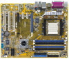
A8N5X Motherboard - Asus A8N5X | A8N5X User's Manual for English Edition - Page 2
express written permission of ASUSTeK COMPUTER INC. ("ASUS"). Product warranty or service will not be extended if: (1) the ASUS HAS BEEN ADVISED OF THE POSSIBILITY OF SUCH DAMAGES ARISING FROM ANY DEFECT OR ERROR IN THIS MANUAL OR PRODUCT. SPECIFICATIONS AND INFORMATION CONTAINED IN THIS MANUAL - Asus A8N5X | A8N5X User's Manual for English Edition - Page 3
direction 1-8 1.5.2 Screw holes 1-8 1.5.3 Motherboard layout 1-9 1.6 Central Processing Unit (CPU 1-10 1.6.1 Overview 1-10 1.6.2 Installling the CPU 1-10 1.6.3 Installing the heatsink and fan 1-12 1.7 System memory 1-15 1.7.1 Overview 1-15 1.7.2 Memory Configurations 1-15 1.7.3 Installing - Asus A8N5X | A8N5X User's Manual for English Edition - Page 4
.1 Rear panel connectors 1-22 1.10.2 Internal connectors 1-24 Chapter 2: BIOS setup 2.1 Managing and updating your BIOS 2-2 2.1.1 Creating a bootable floppy disk 2-2 2.1.2 Updating the BIOS 2-3 2.1.3 Saving the current BIOS file 2-5 2.1.4 ASUS CrashFree BIOS 2 utility 2-6 2.1.5 ASUS EZ Flash - Asus A8N5X | A8N5X User's Manual for English Edition - Page 5
Configuration 2-28 2.4.5 LAN Cable Status 2-30 2.4.6 PEG Link Mode 2-30 2.4.7 Instant Music 2-31 2.5 Power menu 2-32 2.5.1 ACPI Suspend Type 2-32 2.5.2 ACPI APIC Support 2-32 2.5.3 APM Configuration 2-33 2.5.4 Hardware Monitor 2-35 2.6 Boot menu 2-36 2.6.1 Boot Device Priority 2-36 - Asus A8N5X | A8N5X User's Manual for English Edition - Page 6
Contents 3.4 RAID configurations 3-21 3.4.1 Installing hard disks 3-22 3.4.2 NVIDIA® RAID configurations 3-23 3.5 Creating a RAID driver disk 3-30 3.6 Cool 'n' Quiet!™ Technology 3-31 3.6.1 Enabling Cool 'n' Quiet!™ Technology 3-31 3.6.2 Launching the Cool 'n' Quiet!™ software 3-32 vi - Asus A8N5X | A8N5X User's Manual for English Edition - Page 7
with the limits for a Class B digital device, pursuant to Part 15 of the FCC Rules and used in accordance with manufacturer's instructions, may cause harmful interference to radio connected. • Consult the dealer or an experienced radio/TV technician for help. The use of shielded cables for connection - Asus A8N5X | A8N5X User's Manual for English Edition - Page 8
are using, contact your local power company. • If the power supply is broken, do not try to fix it by yourself. Contact a qualified service technician or your retailer. Operation safety • Before installing the motherboard and adding devices on it, carefully read all the manuals that came with the - Asus A8N5X | A8N5X User's Manual for English Edition - Page 9
describes the features of the motherboard and the new technology it supports. It also lists the hardware setup procedures that you have to perform when installing system components. It includes description of the jumpers and connectors on the motherboard. • Chapter 2: BIOS setup This chapter tells - Asus A8N5X | A8N5X User's Manual for English Edition - Page 10
manual. D A N G E R / W A R N I N G : Information to prevent injury to yourself when trying to complete a task. C A U T I O N : Information to prevent damage to the components when trying to complete a task. I M P O R T A N T : Instructions as shown, then supply the required item or value enclosed in - Asus A8N5X | A8N5X User's Manual for English Edition - Page 11
A8N5X specifications summary CPU Socket 939 for AMD Athlon™ 64 X2/AMD Athlon™ 64FX and AMD Athlon™ 64 processors Supports AMD 64 architecture that enables simultaneous 32-bit and 64-bit architecture Supports AMD® Cool 'n' Quiet! Technology Chipset NVIDIA® nForce™ 4 System Bus 1600/2000 MT per - Asus A8N5X | A8N5X User's Manual for English Edition - Page 12
A8N5X specifications summary Internal connectors LAN AI Audio USB Rear panel BIOS features Power Requirement 1 x Floppy disk drive connector 2 x IDE connectors 4 x Serial ATA connectors 1 x CPU fan connector 1 x Power fan connector 2 x Chassis fan connector 1 x Chipset fan connector 1 x Serial - Asus A8N5X | A8N5X User's Manual for English Edition - Page 13
A8N5X specifications summary Form Factor Support CD contents ATX form factor: 12 in x 9.6 in (30.5 cm x 24.4 cm) Device drivers ASUS PC Probe II ASUS Live Update utility ASUS Cool'n'Quiet! utility Anti-virus utility (OEM version) NVIDIA® nTune™ utility *Specifications are subject to change - Asus A8N5X | A8N5X User's Manual for English Edition - Page 14
xiv - Asus A8N5X | A8N5X User's Manual for English Edition - Page 15
This chapter describes the motherboard features and the new technologies it supports. 1Product introduction ASUS A8N5X 1-1 - Asus A8N5X | A8N5X User's Manual for English Edition - Page 16
, and hardware devices on it, check the items in your package with the list below. 1.2 Package contents Check your motherboard package for the following items. Motherboard ASUS A8N5X motherboard I/O modules USB 2.0 2-port module Cables 2 x Serial ATA signal cables 1 x Serial ATA power cables - Asus A8N5X | A8N5X User's Manual for English Edition - Page 17
motherboard supports AMD dual-core processors containing two physical CPU cores with discrete L2 cache structure for each core to meet demands for more powerful circuits in computers, networking and telecommunicatons equipment up to 48 times faster than other existing technologies. ASUS A8N5X 1-3 - Asus A8N5X | A8N5X User's Manual for English Edition - Page 18
into a high-end entertainment system with digital connectivity to powerful audio and speaker systems. See page 1-21 for details. USB 2.0 technology The motherboard implements the Universal Serial Bus (USB) 2.0 specification, dramatically increasing the connection speed from the 12 Mbps bandwidth on - Asus A8N5X | A8N5X User's Manual for English Edition - Page 19
During the bootup process, AI NET 2 immediately diagnoses the LAN cable(s) and reports shorts and faults up to 100 meters at 1 meter accuracy. See pages 2-30 and 3-9 for details. AI Audio technology The motherboard supports 8-channel audio through the onboard ALC850 CODEC with 16-bit DAC, a stereo - Asus A8N5X | A8N5X User's Manual for English Edition - Page 20
you to restore the original BIOS data from the support CD in case when the BIOS codes and data are corrupted. This protection eliminates the need to buy a replacement ROM chip. See details on page 2-5. ASUS Q-Fan technology The ASUS Q-Fan technology smartly adjusts the fan speeds according to the - Asus A8N5X | A8N5X User's Manual for English Edition - Page 21
precautions before you install motherboard components or change any motherboard settings. • Unplug the power cord from the wall socket before touching any component. • Use a grounded wrist strap or touch a safely grounded object or to a metal object, such as the power supply case, before handling - Asus A8N5X | A8N5X User's Manual for English Edition - Page 22
power cord before installing or removing the motherboard. Failure to do so can cause you physical injury and damage motherboard components. 1.5.1 Placement direction When installing the motherboard to secure the motherboard to the chassis. Do not overtighten the screws! Doing so can damage the - Asus A8N5X | A8N5X User's Manual for English Edition - Page 23
In PWR_FAN FP_AUDIO Marvell 88E1111 PCIEX16_1 ACL850 PCIEX1_1 PCIEX1_2 A8N5X nForce4 PCIEX4_1 ® PCI1 CHIP_FAN PCI2 PCI3 SB_PWR CR2032 3V Lithium Cell CMOS Power CLRTC Super I/O USB78 USB56 USB910 SATA4 SATA3 SATA2 SATA1 4Mb BIOS CHA1_FAN CHASSIS GAME COM1 PANEL ASUS A8N5X 1-9 - Asus A8N5X | A8N5X User's Manual for English Edition - Page 24
gold triangle) on the CPU. This mark should match a specific corner on the socket to ensure correct installation. 1.6.2 Installling the CPU To install a CPU: 1. Locate the CPU socket on the motherboard. A8N5X ® A8N5X CPU Socket 939 Before installing the CPU, make sure that the socket box is facing - Asus A8N5X | A8N5X User's Manual for English Edition - Page 25
module base when installing the CPU or installing other motherboard components. • If you purchased a separate CPU heatsink and fan assembly, make sure that a Thermal Interface Material is properly applied to the CPU heatsink or CPU before you install the heatsink and fan assembly. ASUS A8N5X 1-11 - Asus A8N5X | A8N5X User's Manual for English Edition - Page 26
sound denotes that the retention bracket is in place. Make sure that the fan and fan and heatsink assembly is in place, connect the CPU fan cable to the connector on the motherboard. CPU_FAN GND +12V Rotation A8N5X ® A8N5X CPU fan connector 1-12 DO NOT forget to connect the CPU fan connector - Asus A8N5X | A8N5X User's Manual for English Edition - Page 27
. • Due to chipset resource allocation, the system may detect less than 4 GB of system memory when you installed four 1 GB DDR memory modules. • Due to CPU limitation, DIMM modules with 128 Mb memory chips or double-sided x16 memory chips are not supported in this motherboard. ASUS A8N5X 1-13 - Asus A8N5X | A8N5X User's Manual for English Edition - Page 28
slots as one pair of Dual-channel memory configuration. C - support for 4 modules inserted into the blue and black slots as two pairs of Dual-channel memory configuration. Visit the ASUS website (www.asus.com) for the latest DDR 400 Qualified Vendors List. 1-14 Chapter 1: Product introduction - Asus A8N5X | A8N5X User's Manual for English Edition - Page 29
Make sure to unplug the power supply before adding or removing DIMMs or other system components. Failure to do so may cause severe damage to both the motherboard and the components. 1. Unlock a DIMM socket by pressing the retaining clips outward. 2. Align a DIMM on the socket such that the notch on - Asus A8N5X | A8N5X User's Manual for English Edition - Page 30
support. Make sure to unplug the power cord before adding or removing expansion cards. Failure to do so may cause you physical injury and damage motherboard components. We recommended to install the memory motherboard card connector Replace BIOS settings, if any. See Chapter 2 for information on BIOS - Asus A8N5X | A8N5X User's Manual for English Edition - Page 31
will arise between the two PCI groups, making the system unstable and the card inoperable. 1.8.4 PCI slots The PCI slots support cards such as a LAN card, SCSI card, USB card, and other cards that comply with PCI specifications. The figure shows a LAN card installed on a PCI slot. ASUS A8N5X 1-17 - Asus A8N5X | A8N5X User's Manual for English Edition - Page 32
with the PCI Express specifications. The figure shows a network card installed on the PCI Express x1 slot. 1.8.7 Universal PCIe slot (PCI Express x4 slot) This motherboard provides a PCI Express x4 slot that can support PCI Express x1, x4, x8, or x16 cards. This ASUS proprietary slot allows you - Asus A8N5X | A8N5X User's Manual for English Edition - Page 33
battery. 5. Plug the power cord and turn ON the computer. 6. Hold down the key during the boot process and enter BIOS setup to re-enter data. Except when clearing the RTC RAM, never remove the cap on CLRTC jumper default position. Removing the cap will cause system boot failure! A8N5X ® A8N5X - Asus A8N5X | A8N5X User's Manual for English Edition - Page 34
. This 25-pin port connects a parallel printer, a scanner, or other devices. 3 . L A N ( R J - 4 5 ) p o r t . Supported by the NVIDIA® nForce™ 4 Gigabit MAC with external Marvell® PHY, this port allows Gigabit connection to a Local Area Network (LAN) through a network hub. Refer to the table below - Asus A8N5X | A8N5X User's Manual for English Edition - Page 35
Bus (USB) ports are available for connecting USB 2.0 devices. 1 1 . U S B 2 . 0 p o r t s 1 a n d 2 . These two 4-pin Universal Serial Bus (USB) ports are available for connecting USB 2.0 devices. 1 2 . O p t i c a l S / P D I F O u t p o r t. This port connects an external audio output device - Asus A8N5X | A8N5X User's Manual for English Edition - Page 36
match the covered hole on the Ultra DMA cable connector. This prevents incorrect insertion when you connect the IDE cable. • Use the 80-conductor IDE cable for UltraDMA133/100/66 IDE devices. SEC_IDE PRI_IDE A8N5X ® 1-22 A8N5X IDE connectors PIN 1 NOTE: Orient the red markings (usually zigzag - Asus A8N5X | A8N5X User's Manual for English Edition - Page 37
mode, you can connect Serial ATA boot or data hard disk drives to these connectors. If you intent to create a Serial ATA RAID set using these connectors, enable the RAID function of each port from the N V R A I D C o n f i g u r a t i o n sub-menu item in the BIOS. See section "2.4.3 Onboard Devices - Asus A8N5X | A8N5X User's Manual for English Edition - Page 38
system may damage the motherboard components. These are not jumpers! DO NOT place jumper caps on the fan connectors! • The ASUS Q-Fan function is supported using the CPU Fan (CPU_FAN) and Chassis Fan 1 (CHA1_FAN) connectors only. • The chipset fan is synchronized with the CPU fan. GND +12V Rotation - Asus A8N5X | A8N5X User's Manual for English Edition - Page 39
a slot opening at the back of the system chassis. These USB connectors comply with USB 2.0 specification that supports up to 480 Mbps connection speed. USB+5V USB_P10USB_P10 + GND NC A8N5X ® A8N5X USB 2.0 connectors USB+5V USB_P7USB_P7+ GND USB+5V USB_P8USB_P8+ GND NC USB78 1 USB56 1 USB910 - Asus A8N5X | A8N5X User's Manual for English Edition - Page 40
and push down firmly until the connectors completely fit. • Use of a power supply unit (PSU) with a higher power output is recommended when configuring a system with more powerconsuming devices. The system may become unstable or may not boot up if the power is inadequate. • Make sure that your - Asus A8N5X | A8N5X User's Manual for English Edition - Page 41
USB/GAME module cable to this connector, then install the module to a slot opening at the back of the system chassis. The GAME/MIDI port connects a joystick or game pad for playing games, and MIDI devices for playing or editing audio files. +5V J2B1 J2CX MIDI_OUT J2CY J2B2 MIDI_IN A8N5X ® A8N5X - Asus A8N5X | A8N5X User's Manual for English Edition - Page 42
related BIOS item in page 2-42. +5VSB_MB Chassis Signal GND A8N5X ® CHASSIS (Default) A8N5X Chassis intrusion connector 12. Front panel audio connector (10-1 pin FP_AUDIO) This connector is for a chassis-mounted front panel audio I/O module that supports legacy AC '97 audio standard. Connect one - Asus A8N5X | A8N5X User's Manual for English Edition - Page 43
supports several chassis-mounted functions. PLED SPEAKER PLED+ PLED+5V Ground Ground Speaker PANEL IDE_LED+ IDE_LED- PWR Ground Reset Ground A8N5X ® A8N5X System panel connector IDE_LED RESET PWRSW * Requires an ATX power supply. The sytem panel connector is color-coded for easy connection - Asus A8N5X | A8N5X User's Manual for English Edition - Page 44
1-30 Chapter 1: Product introduction - Asus A8N5X | A8N5X User's Manual for English Edition - Page 45
This chapter tells how to change the system settings through the BIOS Setup menus. Detailed descriptions of the BIOS parameters are also provided. 2 BIOS setup ASUS A8N5X 2-1 - Asus A8N5X | A8N5X User's Manual for English Edition - Page 46
BIOS using the ASUS Update or AwardBIOS Flash utilities. 2.1.1 Creating a bootable floppy disk 1. Do either one of the following to create a bootable floppy disk. DOS environment a. Insert a 1.44MB floppy disk into the drive. b. At the DOS prompt, type format A:/S then press . Windows® XP - Asus A8N5X | A8N5X User's Manual for English Edition - Page 47
or the latest motherboard BIOS file to the bootable floppy disk. 2.1.2 Updating the BIOS The Basic Input/Output System (BIOS) can be updated using the AwardBIOS Flash Utility. Follow these instructions to update the BIOS using this utility. 1. Download the latest BIOS file from the ASUS web site - Asus A8N5X | A8N5X User's Manual for English Edition - Page 48
utility verifies the BIOS file in the floppy disk and starts flashing the BIOS file. AwardBIOS Flash Utility for ASUS V1.01 (C) Phoenix Technologies Ltd. All Rights Reserved For NF-KC804-A8N5X-00 DATE: 11 OK 111122223333 No Update 111122223333 Write Fail Warning: Don't Turn Off Power Or Reset - Asus A8N5X | A8N5X User's Manual for English Edition - Page 49
.bin Message: Please Wait! 4. The utility saves the current BIOS file to the floppy disk, then returns to the BIOS flashing process. AwardBIOS Flash Utility for ASUS V1.01 (C) Phoenix Technologies Ltd. All Rights Reserved For NF-KC804-A8N5X-00 DATE: 11/18/2004 Flash Type - SST 49LF004A/B /3.3V - Asus A8N5X | A8N5X User's Manual for English Edition - Page 50
ASUS CrashFree BIOS 2 is an auto recovery tool that allows you to restore the BIOS file when it fails or gets corrupted during the updating process. You can update a corrupted BIOS file using the motherboard support CD or the floppy disk that contains the updated BIOS file. Prepare the motherboard - Asus A8N5X | A8N5X User's Manual for English Edition - Page 51
while updating the BIOS! Doing so can cause system boot failure! 4. Restart the system after the utility completes the updating process. The recovered BIOS may not be the latest BIOS version for this motherboard. Visit the ASUS website (www.asus.com) to download the latest BIOS file. ASUS A8N5X - Asus A8N5X | A8N5X User's Manual for English Edition - Page 52
chip so it is accessible by pressing + during the Power-On Self Tests (POST). To update the BIOS using EZ Flash: 1. Visit the ASUS website (www.asus.com) to download the latest BIOS file for the motherboard. 2. Save the BIOS file to a floppy disk, then restart the system. 3. Press - Asus A8N5X | A8N5X User's Manual for English Edition - Page 53
the BIOS version information. This utility is available in the support CD that comes with the motherboard package. ASUS Update requires an Internet connection either through a network or an Internet Service Provider (ISP). Installing ASUS Update To install ASUS Update: 1. Place the support CD in - Asus A8N5X | A8N5X User's Manual for English Edition - Page 54
e. The ASUS Update main window appears. 2. Select U p d a t e B I O S f r o m 3. Select the ASUS FTP site t h e I n t e r n e t option from the nearest you to avoid network drop-down menu, then click traffic, or click A u t o S e l e c t. N e x t. Click N e x t. 2-10 Chapter 2: BIOS setup - Asus A8N5X | A8N5X User's Manual for English Edition - Page 55
p d a t e. The ASUS Update main window appears. 2. Select U p d a t e B I O S f r o m a f i l e option from the drop-down menu, then click N e x t. 3. Locate the BIOS file from the O p e n window, then click O p e n. 4. Follow the screen instructions to complete the update process. ASUS A8N5X 2-11 - Asus A8N5X | A8N5X User's Manual for English Edition - Page 56
setup program This motherboard supports a programmable Low-Pin Count (LPC) chip that you can update using the provided utility described in section "2.1 Managing and updating your BIOS." Use the BIOS Setup program when you are installing a motherboard, reconfiguring your system, or prompted to "Run - Asus A8N5X | A8N5X User's Manual for English Edition - Page 57
arrow key on the keyboard until the desired item is highlighted. • The BIOS setup screens shown in this chapter are for reference purposes only, and may not exactly match what you see on your screen. • Visit the ASUS website (www.asus.com) to download the latest BIOS information. ASUS A8N5X 2-13 - Asus A8N5X | A8N5X User's Manual for English Edition - Page 58
on the menu bar displays the specific items for that menu. For example, selecting M a i n shows the Main menu items. The other items (Advanced, Power, Boot, and Exit) on the field, select it then press to display a list of options. Refer to "2.2.7 Pop-up window." 2-14 Chapter 2: BIOS setup - Asus A8N5X | A8N5X User's Manual for English Edition - Page 59
a pop-up window with the configuration options for that item. Phoenix-Award BIOS CMOS Setup Utility Main Advanced Power Boot Exit System Time ↑↓ :Move ENTER:Accept ESC:Abort Installed Memory 256MB Select Menu Item Specific Help Specifies the capacity and physical size of ASUS A8N5X 2-15 - Asus A8N5X | A8N5X User's Manual for English Edition - Page 60
navigate through them. Phoenix-Award BIOS CMOS Setup Utility Main Advanced Power Boot Exit System Time System Date Language ] [ASUS CDS520/A] [None] [None] [None] [None] [None] [None] [Disabled] Select Menu Item Specific Help Change the day, month, year and century. Installed Memory 256MB F1 - Asus A8N5X | A8N5X User's Manual for English Edition - Page 61
device information. Main Phoenix-Award BIOS CMOS Setup Utility Primary IDE Master PIO Mode UDMA Mode [Auto] [Auto] Primary IDE Master Access Mode UDMA Mode [Auto] [Auto] [Auto] Select Menu Item Specific the BIOS automatically BIOS may detect incorrect parameters. Select [Manual] to manually - Asus A8N5X | A8N5X User's Manual for English Edition - Page 62
if you set the IDE Primary Master/Slave to [Manual]. Configuration options: [CHS] [LBA] [Large] you have the correct configuration information supplied by the drive manufacturer. Incorrect settings . After entering the IDE hard disk drive information into BIOS, use a disk utility, such as FDISK, to - Asus A8N5X | A8N5X User's Manual for English Edition - Page 63
separate sub-menu for each SATA device. Select a device item then press to display the SATA device information. Main Phoenix-Award BIOS CMOS Setup Utility Extended Drive Access Mode Capacity Primary IDE Master [Auto] [Auto] xxxxx MB Select Menu Item Specific Help Press [Enter] to select - Asus A8N5X | A8N5X User's Manual for English Edition - Page 64
. This item is not configurable. After entering the IDE hard disk drive information into BIOS, use a disk utility, such as FDISK, to partition and format new IDE hard Configuration options: [Disabled] [Enabled] 2.3.8 Installed Memory Shows the size of installed memory. 2-20 Chapter 2: BIOS setup - Asus A8N5X | A8N5X User's Manual for English Edition - Page 65
can cause the system to malfunction. Phoenix-Award BIOS CMOS Setup Utility Main Advanced Power Boot Exit CPU Configuration PCIPnP Onboard Device Configuration JumperFree Configuration LAN Cable Status PEG Link Mode Instant Music Select Menu Item Specific Help Press Enter to Set F1:Help ESC - Asus A8N5X | A8N5X User's Manual for English Edition - Page 66
DDR433] [DDR466] [DDR500] [DDR533] [DDR550] [DDR600] 1T/2T Memory Timing [Auto] Sets the memory timing. Configuration options: [Auto] [1T] [2T] CAS# latency (Tcl [2x] [3x] [4x] [5x] [Auto] AMD K8 Cool'n'Quiet control [Auto] Enables or disables the AMD Cool 'n' Quiet! technology. Configuration options - Asus A8N5X | A8N5X User's Manual for English Edition - Page 67
By [Auto] When set to [Auto], the BIOS automatically configures all the boot and Plug and Play compatible devices. Set to [Manual] if you want to assign the IRQ DMA and memory base address fields. Configuration options: [Auto] [Manual] When the item Resources Controlled By is set to [Auto], the item - Asus A8N5X | A8N5X User's Manual for English Edition - Page 68
Configuration options: [Disabled] [Enabled] 2.4.3 Onboard Devices Configuration Advanced Phoenix-Award BIOS CMOS Setup Utility Onboard Device Configuration IDE Function Setup NVRAID Configuration USB Configuration Onboard NV LAN Onboard LAN Boot ROM AC97 Audio Serial Port1 Address Parallel Port - Asus A8N5X | A8N5X User's Manual for English Edition - Page 69
RAID [Disabled] Disabled Disabled Disabled Disabled Disabled Disabled Disabled Disabled Item Specific Help RAID Enabled [Disabled] Enables or disables the onboard RAID controller. When Enabled, the succeeding items becomes user-configurable. Configuration options: [Enabled] [Disabled] ASUS A8N5X - Asus A8N5X | A8N5X User's Manual for English Edition - Page 70
to enable or disable support for USB devices on legacy operating systems (OS). Configuration options: [Disabled] [Enabled] Onboard NV LAN [Enabled] Enables or disables the onboard NVIDIA® Gigabit LAN controller. Configuration options: [Enabled] [Disabled] OnBoard LAN Boot ROM [Disabled] Allows you - Asus A8N5X | A8N5X User's Manual for English Edition - Page 71
to disable the port. Configuration options: [Disabled] [330] [300] Midi Port IRQ [10] Allows you to set the Midi port IRQ address. Configuration options: [5] [10] ASUS A8N5X 2-27 - Asus A8N5X | A8N5X User's Manual for English Edition - Page 72
Auto Auto Select Menu Item Specific Help Overclock Profile [Auto] Allows selection of CPU overclocking options to achieve desired CPU internal frequency. Select either one of the preset overclocking configuration options: Manual Auto Standard AI Overclock AI N.O.S. Allows you to individually - Asus A8N5X | A8N5X User's Manual for English Edition - Page 73
.5] [x20] CPU Voltage [Auto] Sets the operating CPU voltage. Configuration Overclocking item is set to [AI Overclock]. Overclock Options [Disable] Allows you to set the oveclocking options. Configuration options: [Disable] [Overclock 3%] [Overclock 5%] [Overclock 8%] [Overclock 10%] ASUS A8N5X - Asus A8N5X | A8N5X User's Manual for English Edition - Page 74
of the LAN cable during the Power-On Self-Test (POST). Configuration options: [Disabled] [Enabled] 2.4.6 PEG Link Mode Advanced Phoenix-Award BIOS CMOS Setup Utility JumperFree Configuration PEG Link Mode PEG Root Control PEG Buffer Length [Auto] [Auto] [Auto] Select Menu Item Specific Help - Asus A8N5X | A8N5X User's Manual for English Edition - Page 75
Music CD-ROM Drive [Disabled] Primary Master Select Menu Item Specific Help If enabled, power up by PS/2 keyboard function will be disabled. Instant Music [Disabled] Allows you to enable or disable the ASUS Instant Music feature. Configuration options: [Disabled] [Enabled] Enabling Instant Music - Asus A8N5X | A8N5X User's Manual for English Edition - Page 76
then press to display the configuration options. Phoenix-Award BIOS CMOS Setup Utility Main Advanced Power Boot Exit ACPI Suspend Type ACPI APIC support APM Configuration Hardware Monitor [S1&S3] [Enabled] Select Menu Item Specific Help Select the ACPI state used for System Suspend. F1 - Asus A8N5X | A8N5X User's Manual for English Edition - Page 77
for more than 4 seconds. Configuration options: [Suspend] [Instant-Off] Power On By PCI Devices [Disabled] When set to [Enabled], this parameter allows you to turn on the system through a PCI LAN or modem card. This feature requires an ATX power supply that provides at least 1A on the +5VSB lead - Asus A8N5X | A8N5X User's Manual for English Edition - Page 78
to disable the Power On by PS/2 keyboard function or set specific keys on the PS/2 keyboard to turn on the system. This feature requires an ATX power supply that provides at least 1A on the +5VSB lead. Configuration options: [Disabled] [Space Bar] [Ctrl-ESC] [Power Key] 2-34 Chapter 2: BIOS setup - Asus A8N5X | A8N5X User's Manual for English Edition - Page 79
. CPU Fan Speed CHA1 Fan Speed CHIP Fan Speed The onboard hardware monitor automatically detects and displays the Chassis, CPU, and Chip fan speeds in rotations per minute (RPM). If the fan is not connected to the motherboard, the field shows 0. These items are not user-configurable. ASUS A8N5X - Asus A8N5X | A8N5X User's Manual for English Edition - Page 80
BIOS CMOS Setup Utility Power Boot Device Priority 1st Boot Device 2nd Boot Device 3rd Boot Device 4th Boot Device [Removable] [Hard Disk] [CDROM] [Disabled] Select Menu Item Specific Help Select your boot device priority 1st ~ xxth Boot Device [Removable] These items specify the boot device - Asus A8N5X | A8N5X User's Manual for English Edition - Page 81
Drives Phoenix-Award BIOS CMOS Setup Utility Boot Hard Disk Drives 1. 1st Master: XXXXXXXXX 2. Bootable Add-in Cards Select Menu Item Specific Help 1. CDROM Drives Phoenix-Award BIOS CMOS Setup Utility Boot CDROM Drives 1. 1st Slave: XXXXXXXXX Select Menu Item Specific Help 1. 1st Slave: - Asus A8N5X | A8N5X User's Manual for English Edition - Page 82
connectors" for setting details. Configuration options: [Disabled] [Enabled] Quick Boot [Enabled] Allows you to enable or disable the system quick boot the BIOS to check a boot floppy disk during POST. Configuration options: [Disabled] [Enabled] Bootup Num-Lock [On] Allows you to select the power- - Asus A8N5X | A8N5X User's Manual for English Edition - Page 83
] [All, But Diskette] [All, But Disk/Key] 2.6.6 Security Phoenix-Award BIOS CMOS Setup Utility Boot Boot Settings Configuration Supervisor Password User Password Password Check Clear Clear [Setup] Select Menu Item Specific Help Supervisor Password User Password These fields allow you to set - Asus A8N5X | A8N5X User's Manual for English Edition - Page 84
containing the password information is powered by the onboard button cell battery. If you need to erase the CMOS RAM, refer to section "2.6 Jumpers" for instructions. Password Check This field requires you to enter the password before entering the BIOS setup or the system. Select [Setup] to require - Asus A8N5X | A8N5X User's Manual for English Edition - Page 85
items, and save or discard your changes to the BIOS items. Phoenix-Award BIOS CMOS Setup Utility Main Advanced Power Boot Exit Exit & Save Changes Exit & Discard Changes Load Setup Default Discard Changes Select Menu Item Specific Help This option save data to CMOS and exiting the setup menu. F1 - Asus A8N5X | A8N5X User's Manual for English Edition - Page 86
Setup menus. When you select this option or if you press , a confirmation window appears. Select Y e s to load default values. Select E x i t & s or make other changes before saving the values to the non-volatile RAM. Discard Changes This option allows you to discard the selections you made and - Asus A8N5X | A8N5X User's Manual for English Edition - Page 87
This chapter describes the contents of the support CD that comes with the motherboard package. 3 Software support ASUS A8N5X 3-1 - Asus A8N5X | A8N5X User's Manual for English Edition - Page 88
that you install Windows® 2000 Service Pack 4 or the Windows® XP Service Pack 2 or later versions before installing the drivers for better compatibility and system stability. 3.2 Support CD information The support CD that came with the motherboard package contains the drivers, software applications - Asus A8N5X | A8N5X User's Manual for English Edition - Page 89
ALC850 audio controller and application. AMD Cool'n'Quiet Driver Installs the AMD Cool 'n' Quiet! Technology drivers. USB 2.0 Driver Installs the Universal Serial Bus 2.0 (USB 2.0) driver. The screen display and drivers option may not be the same for different operating system versions. ASUS A8N5X - Asus A8N5X | A8N5X User's Manual for English Edition - Page 90
Update Allows you to download the latest version of the BIOS from the ASUS website. Before using the ASUS Update, make sure that you have an Internet connection so you can connect to the ASUS website. ASUS AI Booster The ASUS AI Booster application allows you to overclock the CPU speed in a Windows - Asus A8N5X | A8N5X User's Manual for English Edition - Page 91
the U t i l i t i e s m e n u before opening a user manual file. • Some user manuals listed in this menu may not be applicable for this motherboard model. NVIDIA Firewall Administrator's Guide Allows you to open the NVIDIA® ForceWare Networking and Firewall Administrator's Guide. ASUS A8N5X 3-5 - Asus A8N5X | A8N5X User's Manual for English Edition - Page 92
open the NVIDIA® RAID User's Guide. Sil3114 User's Manual Allows you to open the Silicon Image RAID User's Guide. NVIDIA nTune Manual Allows you to open the NVIDIA® nTune™ user's manual. NvRAID Disk Alert User's Guide Allows you to open the NVIDIA® NVRAID™ Disk Alert user's guide. 3.2.5 ASUS Contact - Asus A8N5X | A8N5X User's Manual for English Edition - Page 93
boot logo is the image that appears on screen during the Power-On Self-Tests (POST). The ASUS MyLogo2™ is automatically installed when you install the A S U S U p d a t e utility from the support CD. See section "3.2.3 Utilities menu" for details. • Before using the ASUS MyLogo2™, use the Award BIOS - Asus A8N5X | A8N5X User's Manual for English Edition - Page 94
to your desired size by selecting a value on the R a t i o box. 9. When the screen returns to the ASUS Update utility, flash the original BIOS to load the new boot logo. 10. After flashing the BIOS, restart the computer to display the new boot logo during POST. 3-8 Chapter 3: Software support - Asus A8N5X | A8N5X User's Manual for English Edition - Page 95
window is disabled if no problem is detected on the LAN cable(s) connected to the LAN port(s). • If you want the system to check the LAN cable before entering the OS, enable the P O S T C h e c k L A N c a b l e item in the BIOS. See section "2.4.5 LAN Cable Status" for details. ASUS A8N5X 3-9 - Asus A8N5X | A8N5X User's Manual for English Edition - Page 96
from the support CD that came with the motherboard package. If the Realtek audio software is Audio Control Panel. Realtek SoundEffect icon The Jack-sensing and UAJ® technology features are supported on the Line-In, Line-Out, and Mic jacks only. Sound Effect options The Realtek® ALC850 Audio - Asus A8N5X | A8N5X User's Manual for English Edition - Page 97
to change your S/PDIF output settings. To set the S/PDIF options: 1. From the Realtek Audio Control Panel, click the S P D I F button. 2. Click the option buttons to change your S/PDIF out settings. 3. Click the Exit (X ) button on the upper-right hand corner of the window to exit. ASUS A8N5X 3-11 - Asus A8N5X | A8N5X User's Manual for English Edition - Page 98
Realtek Audio Control Panel, click the S p e a k e r C o n f i g u r a t i o n button. 2. Select from the combo list box disable the Universal Audio Jack(UAJ®) technology feature. 4. Click the Exit (X ) button on the upper-right hand corner of the window to exit. 3-12 Chapter 3: Software support - Asus A8N5X | A8N5X User's Manual for English Edition - Page 99
allows you to check if your audio devices are connected properly. To start the connector sensing: 1. From the Realtek Audio Control Panel, click the C o n n e c t o r S e n s i n g button. 2. Click the B r a c k e t button to display connected audio devices. 3. Click the O p t i o n button to change - Asus A8N5X | A8N5X User's Manual for English Edition - Page 100
there are detected problems, make sure that your audio cables are connected to the proper audio jack and repeat connector sensing. 7. Click the X button to exit EZ-connection dialog box. 8. Click the Exit (X ) button on the upper-right hand corner of the window to exit audio control panel. HRTF Demo - Asus A8N5X | A8N5X User's Manual for English Edition - Page 101
Audio Control Panel, click the G e n e r a l button. 2. Click the option button to enable or disable the icon display on the Windows taskbar. 3. Click the L a n g u a g e combo list or 8-channel audio configuration. See the 8, 6, 4 or 2-channel speaker configuration on page 1-21. ASUS A8N5X 3-15 - Asus A8N5X | A8N5X User's Manual for English Edition - Page 102
motherboard supports the NVIDIA® Firewall™ (NVFirewall™) application that protects your computer from intruders. The NVFirewall™ is classified as a personal firewall or desktop firewall that works at the device level to protect your system from malicious computer code by controlling the connections - Asus A8N5X | A8N5X User's Manual for English Edition - Page 103
connections and deny those that are known to be dangerous connections connections. Incoming connections connections n - blocks all incoming and outgoing connections. • A n t i - h e w a l l P r o f i l e combo list box then select a security profile. The following confirmation box appears. 2. Click - Asus A8N5X | A8N5X User's Manual for English Edition - Page 104
or intruders after you turn off the firewall. To turn off the NVFirewall: 1. From the NVIDIA Firewall summary menu, click the Current Firewall Profile combo list box then select O f f. The following confirmation box appears. 2. Click T u r n F i r e w a l l O F F. 3-18 Chapter 3: Software - Asus A8N5X | A8N5X User's Manual for English Edition - Page 105
. If you want to boot the system from a hard disk drive included in a RAID set, copy first the RAID driver from the support CD to a floppy disk before you install an operating system to a selected hard disk drive. Refer to section "3.5 Creating a RAID driver disk" for details. ASUS A8N5X 3-19 - Asus A8N5X | A8N5X User's Manual for English Edition - Page 106
the SATA hard disks for a RAID configuration: 1. Install the SATA hard disks into the drive bays. 2. Connect the SATA signal cables. 3. Connect a SATA power cable to the power connector on each drive. Refer to the RAID controllers user manual in the motherboard support CD for detailed information on - Asus A8N5X | A8N5X User's Manual for English Edition - Page 107
(s) that you want to configure as RAID. See section "2.4.3 Onboard Devices Configuration" for details. 4. Save your changes and Exit Setup. For detailed descriptions on the NVIDIA® RAID configuration, refer to the "NVIDIA® RAID User's Manual" found in your motherboard support CD. ASUS A8N5X 3-21 - Asus A8N5X | A8N5X User's Manual for English Edition - Page 108
To enter the NVIDIA® RAID utility: 1. Boot up your computer. 2. During POST, press to display the main menu of the utility. The RAID BIOS setup screens shown in this section are for reference only, and may not exactly match the items on your screen. NVIDIA RAID Utility Oct 5 2004 - Define - Asus A8N5X | A8N5X User's Manual for English Edition - Page 109
keys to select the stripe size for your RAID 0 array then press .The available . For multimedia computer systems used mainly for audio and video editing, a higher array block size assign the array disks. 4. Press to create RAID set. The following message box appears. Clear disk data - Asus A8N5X | A8N5X User's Manual for English Edition - Page 110
MIRROR XXX.XXG [Ctrl-X]Exit [↑↓]Select [B]Set Boot [N]New Array [ENTER]Detail A new set of navigation keys is displayed on the bottom of the screen. 6. Press to save settings and exit. Rebuilding a RAID array To rebuild a RAID array: 1. From the Array List menu, use the up or down arrow - Asus A8N5X | A8N5X User's Manual for English Edition - Page 111
to rebuild a RAID array. The following screen appears. Array 1 : NVIDIA MIRROR XXX.XXG - Select Disk Inside Array - RAID Mode: Mirroring Striping [F7] Finish 3. Use the up or down arrow keys to select a RAID array to rebuild, then press . The following confirmation message appears. Rebuild - Asus A8N5X | A8N5X User's Manual for English Edition - Page 112
RAID array then press . The RAID Array details appear. Array 1 : NVIDIA MIRROR XXX.XXG - Array Detail - RAID of the screen. 2. Press to delete a RAID array. The following confirmation message appears. Delete this option. All data on the RAID drives will be lost! 4. If you selected Yes - Asus A8N5X | A8N5X User's Manual for English Edition - Page 113
appears. Clear disk data? [Y] YES [N] 5. Press to clear the disk data or press to cancel. Take caution in using this option. All data on the RAID drives will be lost! ASUS A8N5X 3-27 - Asus A8N5X | A8N5X User's Manual for English Edition - Page 114
to boot from the support CD. Save your changes, then exit the BIOS Setup. 4. Restart the computer. The following screen appears during POST. 1) Make Sil3114 32bit SATA/RAID Driver Disk 2) Make Sil3114 64bit SATA/RAID Driver Disk 3) Make Nvidia 2000 RAID Driver Disk 4) Make Nvidia XP RAID Driver Disk - Asus A8N5X | A8N5X User's Manual for English Edition - Page 115
t and set it to Y e s. See section "2.5 Power Menu" in the user guide. 4. Save your changes and exit BIOS Setup. 5. Reboot your computer and set your Power Option Properties depending on your operating system. Windows® 2000/XP 1. From the Windows® 2000/XP operating system, click the S t a r t button - Asus A8N5X | A8N5X User's Manual for English Edition - Page 116
!™ software from the motherboard support CD. Refer to section "3.2.3 Utilities menu", for details. To launch the Cool 'n' Quiet!™ program: 1. If you are using Windows® 2000, click the S t a r t button. Select Programs > ASUS > Cool & Quiet > Cool & Quiet. 2. If you are using Windows® XP, click the
-
 1
1 -
 2
2 -
 3
3 -
 4
4 -
 5
5 -
 6
6 -
 7
7 -
8
-
9
-
10
-
11
-
12
-
13
-
14
-
15
-
16
-
17
-
18
-
19
-
20
-
21
-
22
-
23
-
24
-
25
-
26
-
27
-
28
-
29
-
30
-
31
-
32
-
33
-
34
-
35
-
36
-
37
-
38
-
39
-
40
-
41
-
42
-
43
-
44
-
45
-
46
-
47
-
48
-
49
-
50
-
51
-
52
-
53
-
54
-
55
-
56
-
57
-
58
-
59
-
60
-
61
-
62
-
63
-
64
-
65
-
66
-
67
-
68
-
69
-
70
-
71
-
72
-
73
-
74
-
75
-
76
-
77
-
78
-
79
-
80
-
81
-
82
-
83
-
84
-
85
-
86
-
87
-
88
-
89
-
90
-
91
-
92
-
93
-
94
-
95
-
96
-
97
-
98
-
99
-
100
-
101
-
102
-
103
-
104
-
105
-
106
-
107
-
108
-
109
-
110
-
111
-
112
-
113
-
114
-
115
-
116
 |
 |

Motherboard
A8N5X