Asus A8NLA A8N-SLI English edition user's manual, version E2068
Asus A8NLA Manual
 |
View all Asus A8NLA manuals
Add to My Manuals
Save this manual to your list of manuals |
Asus A8NLA manual content summary:
- Asus A8NLA | A8N-SLI English edition user's manual, version E2068 - Page 1
A8N-SLI Motherboard - Asus A8NLA | A8N-SLI English edition user's manual, version E2068 - Page 2
express written permission of ASUSTeK COMPUTER INC. ("ASUS"). Product warranty or service will not be extended if: (1) the ASUS HAS BEEN ADVISED OF THE POSSIBILITY OF SUCH DAMAGES ARISING FROM ANY DEFECT OR ERROR IN THIS MANUAL OR PRODUCT. SPECIFICATIONS AND INFORMATION CONTAINED IN THIS MANUAL - Asus A8NLA | A8N-SLI English edition user's manual, version E2068 - Page 3
Notices vi Safety information vii A8N-SLI specifications summary viii Chapter 1: Hardware information 1.1 Before you proceed 1-2 1.2 Motherboard overview 1-3 1.2.1 Placement direction 1-3 1.2.2 Screw holes 1-3 1.2.3 Motherboard layout 1-4 1.2.4 Layout contents 1-5 1.3 Central Processing - Asus A8NLA | A8N-SLI English edition user's manual, version E2068 - Page 4
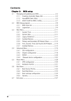
Second, Third, and Fourth SATA Master ..... 2-14 2.3.7 Installed Memory 2-15 2.4 Advanced Menu 2-16 2.4.1 CPU configuration 2-17 2.4.2 Chipset configuration 2-18 2.4.3 PCIPnP 2-20 2.4.4 Onboard device configuration 2-22 2.5 Power Menu 2-28 2.5.1 APM configuration 2-29 2.5.2 Hardware monitor - Asus A8NLA | A8N-SLI English edition user's manual, version E2068 - Page 5
Chapter 3: NVIDIA® SLI™ technology support 3.1 Overview 3-2 3.1.1 Requirements 3-2 3.1.2 ASUS Certified SLI Graphics cards 3-2 3.2 Dual graphics card setup 3-4 3.2.1 Setting the ASUS EZ selector card 3-4 3.2.2 Installing SLI-ready graphics cards 3-6 3.2.3 Installing the device drivers 3-10 - Asus A8NLA | A8N-SLI English edition user's manual, version E2068 - Page 6
and, if not installed and used in accordance with manufacturer's instructions, may cause harmful interference to radio communications. However, there is reception, which can be determined by turning the equipment off and on, the user is encouraged to try to correct the interference by one or more of - Asus A8NLA | A8N-SLI English edition user's manual, version E2068 - Page 7
Contact a qualified service technician or your retailer. Operation safety • Before installing the motherboard and adding devices on it, carefully read all the manuals that came with . • If you encounter technical problems with the product, contact a qualified service technician or your retailer. vii - Asus A8NLA | A8N-SLI English edition user's manual, version E2068 - Page 8
A8N-SLI specifications summary CPU Chipset Front Side Bus Memory Expansion slots Storage Audio LAN IEEE 1394 Socket 939 for AMD Athlon™ 64FX/AMD Athlon™ 64 processor Supports AMD 64 architecture that enables simultaneous 32-bit and 64-bit architecture NVIDIA® nForce™4 SLI 1 GHz (K8) / 800 MHz Dual - Asus A8NLA | A8N-SLI English edition user's manual, version E2068 - Page 9
A8N-SLI specifications summary Rear panel Internal connectors Power requirement Form factor 1 x PS/2 mouse port 1 x Parallel port 1 x IEEE 1394a port 1 x LAN (RJ-45) port 4 x USB 2.0 ports 1 x Coaxial S/PDIF Out port 1 x Optical S/PDIF Out port 1 x PS/2 keyboard port 8-Channel audio ports 1 x - Asus A8NLA | A8N-SLI English edition user's manual, version E2068 - Page 10
x - Asus A8NLA | A8N-SLI English edition user's manual, version E2068 - Page 11
This chapter lists the hardware setup procedures that you have to perform when installing system components. It includes description of the jumpers and connectors on the motherboard. Hardware information - Asus A8NLA | A8N-SLI English edition user's manual, version E2068 - Page 12
before removing or plugging in any motherboard component. The red warning LED lights up when you installed two graphics cards but did not connect the ASUS EZ Plug™. The illustration below shows the location of the onboard LEDs. SLI_WARN_LED A8N-SLI ® A8N-SLI Onboard LED ON When use 2 Graphics - Asus A8NLA | A8N-SLI English edition user's manual, version E2068 - Page 13
chassis as indicated in the image below. 1.2.2 Screw holes Place nine screws into the holes indicated by circles to secure the motherboard to the chassis. Do not overtighten the screws! Doing so can damage the motherboard. Place this side towards the rear of the chassis A8N-SLI ASUS A8N-SLI 1-3 - Asus A8NLA | A8N-SLI English edition user's manual, version E2068 - Page 14
1.2.3 Motherboard layout 24 A8N-SLI SLI_CON PCIEX1_2 PCIEX16_2 ® PCI1 NVIDIA® nForce™4 SLI CHIP_FAN 1394 Controller IE_1394_2 PCI2 PCI3 SB_PWR CR2032 3V Lithium Cell CMOS Power CLRTC Super I/O USB78 USB56 USB910 COM1 4Mb BIOS - Asus A8NLA | A8N-SLI English edition user's manual, version E2068 - Page 15
Clear RTC RAM (3-pin USB 2.0 ports 3 and 4 11. USB 2.0 ports 1 and 2 12. IEEE 1394a port 13. Optical S/PDIF Out port 14. Coaxial S/PDIF Out port 15. PS/2 keyboard port Page 1-12 1-16 1-16 1-16 Page 1-17 Page 1-18 1-18 1-18 1-18 1-18 1-18 1-18 1-19 1-19 1-19 1-19 1-19 1-19 1-19 1-19 ASUS A8N-SLI - Asus A8NLA | A8N-SLI English edition user's manual, version E2068 - Page 16
connectors (3-pin CHA1_FAN, CHA2_FAN) 7. Chipset fan connector (3-pin CHIP_FAN) 8. Power fan connector (3-pin PWR_FAN) 9. USB connectors (10-1 pin USB78, USB56, ATX12V1, 4-pin EZ_PLUG) 12. Internal audio connectors (4-pin AUX, 4-pin CD) 13. Front panel audio connector (10-1 pin FP_AUDIO) 14. Chassis - Asus A8NLA | A8N-SLI English edition user's manual, version E2068 - Page 17
note of the marked corner (with gold triangle) on the CPU. This mark should match a specific corner on the socket to ensure correct installation. Gold triangle 1.3.1 Installing the CPU To install a CPU: 1. Locate the CPU socket on the motherboard. A8N-SLI ® A8N-SLI CPU Socket 939 ASUS A8N-SLI 1-7 - Asus A8NLA | A8N-SLI English edition user's manual, version E2068 - Page 18
2. Unlock the socket by pressing the lever sideways, then lift it up to a 90°-100° angle. Socket lever Make sure that the socket lever is lifted up to 90°-100° angle; otherwise the CPU does not fit in completely. 3. Position the CPU above the socket such that the CPU corner with the gold triangle - Asus A8NLA | A8N-SLI English edition user's manual, version E2068 - Page 19
Athlon™ 64 processor requires a specially when installing the CPU or installing other motherboard components. • If you purchased a instructions for the CPU, heatsink, and the retention mechanism. If the instructions in this section do not match the CPU documentation, follow the latter. ASUS A8N-SLI - Asus A8NLA | A8N-SLI English edition user's manual, version E2068 - Page 20
2. Attach one end of the retention bracket to the retention module base. 3. Align the other end of the retention bracket (near the retention bracket lock) to the retention module base. A clicking sound denotes that the retention bracket is in place. Make sure that the fan and heatsink assembly - Asus A8NLA | A8N-SLI English edition user's manual, version E2068 - Page 21
and heatsink assembly is in place, connect the CPU fan cable to the connector on the motherboard labeled CPU_FAN. CPU_FAN A8N-SLI ® A8N-SLI CPU fan connector Do not forget to connect the CPU fan connector! Hardware monitoring errors can occur if you fail to plug this connector. ASUS A8N-SLI 1-11 - Asus A8NLA | A8N-SLI English edition user's manual, version E2068 - Page 22
following figure illustrates the location of the sockets: DIMM_A1 DIMM_A2 DIMM_B1 DIMM_B2 A8N-SLI ® A8N-SLI 184-pin DDR DIMM sockets Channel Channel A Channel B Sockets DIMM_A1 and DIMM_A2 DIMM_B1 and DIMM_B2 1.4.2 Memory configurations You may install 256 MB, 512 MB and 1 GB unbuffered non - Asus A8NLA | A8N-SLI English edition user's manual, version E2068 - Page 23
to do so may cause severe damage to both the motherboard and the components. 1. Unlock a DIMM socket by Support the DIMM lightly with your fingers when pressing the retaining clips. The DIMM might get damaged when it flips out with extra force. 2. Remove the DIMM from the socket. ASUS A8N-SLI - Asus A8NLA | A8N-SLI English edition user's manual, version E2068 - Page 24
support if your motherboard is already configure it by adjusting the software settings. 1. Turn on the system and change the necessary BIOS settings, if any. See Chapter 2 for information on BIOS setup. 2. Assign an IRQ to the card. Refer to the tables on the next page. 3. Install the software drivers - Asus A8NLA | A8N-SLI English edition user's manual, version E2068 - Page 25
- Onboard 1394a shared - - -- - - - When using PCI cards on shared slots, ensure that the drivers support "Share IRQ" or that the cards do not need IRQ assignments; otherwise, conflicts will arise between the two PCI groups, making the system unstable and the card inoperable. ASUS A8N-SLI 1-15 - Asus A8NLA | A8N-SLI English edition user's manual, version E2068 - Page 26
Express x16 graphic cards that comply with the PCI Express specifications. The figure shows a graphics card installed on the PCI Express x16 slot. This motherboard does not support the Scalable Link Interface™ (SLI) mode for two identical SLI™-ready PCI Express x16 graphics cards. Single card mode - Asus A8NLA | A8N-SLI English edition user's manual, version E2068 - Page 27
RTC) RAM in CMOS. You can clear the CMOS memory of date, time, and system setup parameters by erasing the CMOS RTC RAM data. The onboard button cell battery powers the RAM data in down and reboot the system so the BIOS can automatically reset parameter settings to default values. ASUS A8N-SLI 1-17 - Asus A8NLA | A8N-SLI English edition user's manual, version E2068 - Page 28
L A N 2 ( R J - 4 5 ) p o r t . Supported by the Marvell® 88E81111 Gigabit LAN controller, this port allows Gigabit connection to a Local Area audio configuration. 5 . S i d e S p e a k e r O u t p o r t ( b l a c k ) . This port connects the side speakers in an 8-channel audio configuration. - Asus A8NLA | A8N-SLI English edition user's manual, version E2068 - Page 29
an external audio output device via an optical S/PDIF cable. 1 4 . C o a x i a l S / P D I F O u t p o r t . This port connects an external audio output device via a coaxial S/PDIF cable. 1 5 . P S / 2 k e y b o a r d p o r t ( p u r p l e ) . This port is for a PS/2 keyboard. ASUS A8N-SLI 1-19 - Asus A8NLA | A8N-SLI English edition user's manual, version E2068 - Page 30
is removed to prevent incorrect cable connection when using an FDD cable with a covered Pin 5. A8N-SLI ® FLOPPY NOTE: Orient the red markings on the floppy ribbon cable to PIN 1. PIN 1 A8N-SLI Floppy disk drive connector 2 . Serial port connector (10-1 pin COM1) This connector is for a serial - Asus A8NLA | A8N-SLI English edition user's manual, version E2068 - Page 31
for the primary IDE connector on the motherboard, a black connector for an Ultra install two hard disk drives, you must configure the second drive as a slave device A8N-SLI ® A8N-SLI IDE connectors PIN 1 NOTE: Orient the red markings (usually zigzag) on the IDE ribbon cable to PIN 1. ASUS A8N-SLI - Asus A8NLA | A8N-SLI English edition user's manual, version E2068 - Page 32
sub-menu item in the BIOS. See section "2.4.3 Onboard Devices Configuration" on pages 2-24 and 2-26 for details. GND RSATA_RXN4 RSATA_RXP4 GND RSATA_TXN4 RSATA_TXP4 GND GND RSATA_RXN3 RSATA_RXP3 GND RSATA_TXN3 RSATA_TXP3 GND A8N-SLI ® A8N-SLI SATA connectors SATA4 SATA2 GND RSATA_RXN2 RSATA_RXP2 - Asus A8NLA | A8N-SLI English edition user's manual, version E2068 - Page 33
The chipset fan connector is for the NVIDIA® nForce™4 SLI chipset. Connect the fan cable to the fan connector on the motherboard. A8N-SLI ® PWR_FAN CHIP_FAN CHA1_FAN A8N-SLI Fan connectors CHA2_FAN PWR_FAN CHIP_FAN GND +12V Rotation GND +12V Rotation CHA1_FAN GND +12V Rotation ASUS A8N-SLI - Asus A8NLA | A8N-SLI English edition user's manual, version E2068 - Page 34
system chassis. These USB connectors comply with USB 2.0 specification that supports up to 480 Mbps connection speed. A8N-SLI ® USB+5V USB_P10USB_P10 + GND NC USB+5V USB_P6USB_P6+ GND NC USB+5V USB_P8USB_P8+ GND NC USB+5V USB_P9USB_P9+ GND A8N-SLI USB 2.0 connectors USB+5V USB_P7USB_P7+ GND - Asus A8NLA | A8N-SLI English edition user's manual, version E2068 - Page 35
DC GND A8N-SLI EZ_PLUG ® +5V EZ_DET GND +12V A8N-SLI ATX power connectors +3 Volts -12 Volts Ground PSON# Ground Ground Ground -5 Volts +5 Volts +5 Volts +5 Volts Ground +3 Volts +3 Volts Ground +5 Volts Ground +5 Volts Ground Power OK +5V Standby +12 Volts +12 Volts +3 Volts ASUS A8N-SLI - Asus A8NLA | A8N-SLI English edition user's manual, version E2068 - Page 36
Ground Ground Left Audio Channel Left Audio Channel Ground Ground Right Audio Channel A8N-SLI Internal audio connectors 10. Front panel audio connector (10-1 pin FP_AUDIO) This connector is for a chassis-mounted front panel audio I/O module that supports legacy AC '97 audio standard. Connect one - Asus A8NLA | A8N-SLI English edition user's manual, version E2068 - Page 37
labeled "Chassis Signal" and "Ground" are shorted with a jumper cap. Remove the jumper caps only when you intend to use the chassis intrusion detection feature. A8N-SLI ® CHASSIS (Default) A8N-SLI Chassis alarm lead +5VSB_MB Chassis Signal GND ASUS A8N-SLI 1-27 - Asus A8NLA | A8N-SLI English edition user's manual, version E2068 - Page 38
supports several chassis-mounted functions. PLED PWRSW PLED+ PLEDPWR GND A8N-SLI F_PANEL IDE_LED+ IDE_LED- Ground Reset NC ® IDE_LED RESET * Requires an ATX power supply. A8N-SLI system in SLEEP or SOFT-OFF mode depending on the BIOS settings. Pressing the power switch for more than four - Asus A8NLA | A8N-SLI English edition user's manual, version E2068 - Page 39
This chapter tells how to change the system settings through the BIOS Setup menus. Detailed descriptions of the BIOS parameters are also provided. 2 BIOS setup - Asus A8NLA | A8N-SLI English edition user's manual, version E2068 - Page 40
s k in case you need to restore the BIOS in the future. Copy the original motherboard BIOS using the ASUS Update or AFLASH utilities. • Visit the system builder's website and download the latest BIOS file for this motherboard using the ASUS Update utility. 2.1.1 Creating a bootable floppy disk 1. Do - Asus A8NLA | A8N-SLI English edition user's manual, version E2068 - Page 41
. e. Press , then follow screen instructions to continue. 2. Copy the original or the latest motherboard BIOS file to the bootable floppy disk. 2.1.2 AwardBIOS Flash Utility The Basic Input/Output System (BIOS) can be updated using the built-in Flash Memory Writer utility or using a bootable - Asus A8NLA | A8N-SLI English edition user's manual, version E2068 - Page 42
Utility. 5. At the prompt, type a w d f l a s h then press AwardBIOS Flash Utility for ASUS V1.09 (C) Phoenix Technologies Ltd. All Rights Reserved . The Award For NF-KC804-A8N-SLI-00 DATE: 11/30/2004 BIOS Flash Utility screen Flash Type - SST 49LF004A/B /3.3V appears. File Name to - Asus A8NLA | A8N-SLI English edition user's manual, version E2068 - Page 43
Flash Type - SST 49LF004A/B /3.3V flashed the BIOS file. File Name to Program: 1001-001.bin Remove the floppy disk then press to Flashing Complete Press to Continue restart the system. 111222333 Write OK 111222333 No Update 111222333 Write Fail F1 Reset ASUS A8N-SLI 2-5 - Asus A8NLA | A8N-SLI English edition user's manual, version E2068 - Page 44
: old.bin Message: Please Wait! 4. The utility saves the current BIOS file to the floppy disk, then returns to the BIOS flashing process. AwardBIOS Flash Utility for ASUS V1.09 (C) Phoenix Technologies Ltd. All Rights Reserved For NF-KC804-A8N-SLI-00 DATE: 11/30/2004 Flash Type - SST 49LF004A - Asus A8NLA | A8N-SLI English edition user's manual, version E2068 - Page 45
BIOS recovery... Checking for floppy... Floppy found! Reading file "A8N-SLI.ROM". Completed. Start flashing... DO NOT shut down or reset the system while updating the BIOS! Doing so can cause system boot failure! 4. Restart the system after the utility completes the updating process. ASUS A8N-SLI - Asus A8NLA | A8N-SLI English edition user's manual, version E2068 - Page 46
supports a programmable Flash ROM that you can update using the provided utility described in section "2.1 Managing and updating your BIOS." Use the BIOS Setup program when you are installing a motherboard, reconfiguring your system, or prompted to "Run Setup." This section explains how to configure - Asus A8NLA | A8N-SLI English edition user's manual, version E2068 - Page 47
BIOS menu bar The top of the screen has a menu bar with the following selections: MAIN Use this menu to make changes to the basic system configuration. ADVANCED Use this menu to enable and make changes to the advanced features. POWER Use this menu to configure exits Setup ASUS A8N-SLI 2-9 - Asus A8NLA | A8N-SLI English edition user's manual, version E2068 - Page 48
General help In addition to the Item Specific Help window, the BIOS setup program also provides a General Help screen. You may launch this screen from any menu by simply pressing . The General Help screen lists the - Asus A8NLA | A8N-SLI English edition user's manual, version E2068 - Page 49
drive installed. Configuration options: [None] [360K, 5.25 in.] [1.2M , 5.25 in.] [720K , 3.5 in.] [1.44M, 3.5 in.] [2.88M, 3.5 in.] 2.3.4 Installed Memory [xxxMB] This field automatically displays the amount of conventional memory detected by the system during the boot process. ASUS A8N-SLI 2-11 - Asus A8NLA | A8N-SLI English edition user's manual, version E2068 - Page 50
Master [Auto] Access Mode [Auto] Select Menu Item Specific Help Press [Enter] to select. Capacity 13579 MB BIOS may detect incorrect parameters. Select [Manual] to manually enter the IDE hard disk drive parameters. If no drive is installed select [None]. Configuration options: [None] [Auto] [Manual - Asus A8NLA | A8N-SLI English edition user's manual, version E2068 - Page 51
disk drive information into BIOS, use a disk utility, such as FDISK, to partition and format new IDE hard disk drives. This is necessary so that you can write or read data from the hard disk. Make sure to set the partition of the Primary IDE hard disk drives to active. ASUS A8N-SLI 2-13 - Asus A8NLA | A8N-SLI English edition user's manual, version E2068 - Page 52
Menu Item Specific Help Sets the type of fixed disk connected to the system. The BIOS automatically detects the values opposite the dimmed items (Capacity, Cylinder, Head, Precomp, Landing Zone and Sector). These values are not user-configurable. These items show 0 if no SATA device is installed - Asus A8NLA | A8N-SLI English edition user's manual, version E2068 - Page 53
track. This item is not configurable. Sector Shows the number of sectors per track. This item is not configurable. After entering the IDE hard disk drive information into BIOS, use a disk utility, disk drives to active. 2.3.7 Installed Memory Shows the size of installed memory. ASUS A8N-SLI 2-15 - Asus A8NLA | A8N-SLI English edition user's manual, version E2068 - Page 54
other system devices. Take caution when changing the settings of the Advanced menu items. Incorrect field values may cause the system to malfunction. CPU Configuration Chipset PCIPnP Onboard Device Configuration SLI Configuration Select Menu Item Specific Help Press Enter to set. 2-16 Chapter - Asus A8NLA | A8N-SLI English edition user's manual, version E2068 - Page 55
2200MHz Cache RAM 512K AMD K8 Cool 'n' Quiet control [Enabled] Select Menu Item Specific Help Enable/Disable Cool`n'Quiet function. AMD K8 Cool 'n' Quiet control [Enabled] Enables or disables the AMD K8 Cool `n' Quiet™ feature. Configuration options: [Enabled] ~ [Disabled] ASUS A8N-SLI 2-17 - Asus A8NLA | A8N-SLI English edition user's manual, version E2068 - Page 56
(Trp) 2T x 1/T/2T Memory Timing 2T Bottom of 32-bit [31:24] IO DRAM Over 4G Remapping [Disabled] MTRR mapping mode [Continuous] 200Mhz 8T 4T [E0] Select Menu Item Specific Help to select DRAM configuration. [Auto] is recommended. [Manual] allows you to set each configuration on your own - Asus A8NLA | A8N-SLI English edition user's manual, version E2068 - Page 57
to [Manual] Bottom of 32-bit [31:24] IO [E0] Allows you to se the minumum and maximum limits of the 32-bit memory-mapped IO location. DRAM Over 4G Remapping [Disabled] Enables or disables DRAM remapping when using 4 GB of system memory. Configuration options: [Disabled] [Enabled] ASUS A8N-SLI 2-19 - Asus A8NLA | A8N-SLI English edition user's manual, version E2068 - Page 58
By x IRQ Resources PCI/VGA Palette Snoop [Yes] [PCIEx] [Auto] [Disabled] Select Menu Item Specific Help Select Yes if you are using a Plug and Playcapable operating system. Select No if you need the BIOS to configure non-boot devices. Plug & Play OS [Yes] Select [Yes] if you are using a Plug and - Asus A8NLA | A8N-SLI English edition user's manual, version E2068 - Page 59
B y item is set to Manual. IRQ-3 assigned to IRQ-4 Specific Help Legacy ISA for devices compliant with the original PC AT bus specification problem. If you are using standard VGA cards, leave this field to the default setting [Disabled]. Configuration options: [Disabled] [Enabled] ASUS A8N-SLI - Asus A8NLA | A8N-SLI English edition user's manual, version E2068 - Page 60
USB Configuration Onboard LAN Onboard LAN Boot ROM AC97 Audio [Enabled] [Disabled] [Enabled] PCI IEEE 1394a Serial Port 1 Address Parallel Port Address Parallel Port Mode ECP Mode Use DMA [Enabled] [3F8/IRQ4] [378/IRQ7] [ECP+EPP] 3 Select Menu Item Specific Help 2-22 Chapter 2: BIOS - Asus A8NLA | A8N-SLI English edition user's manual, version E2068 - Page 61
: [Disabled] [Enabled] Serial-ATA 1 [Enabled] Allows you to enable or disable the Serial ATA 1 port. Configuration options: [Disabled] [Enabled] SATA DMA transfer [Enabled] Allows you to enable or disable the SATA DMA transfer access. Configuration options: [Disabled] [Enabled] ASUS A8N-SLI 2-23 - Asus A8NLA | A8N-SLI English edition user's manual, version E2068 - Page 62
RAID Disabled RAID Disabled Select Menu Item Specific Help Disable/Enable nVIDIA RAID feature. RAID Enable [Disabled] Enables or disables the onboard RAID controller. When Enabled, the succeeding items become user-configurable. Configuration options: [Enabled] [Disabled] IDE Primary and Secondary - Asus A8NLA | A8N-SLI English edition user's manual, version E2068 - Page 63
[Enabled] Allows you to enable or disable the USB 2.0 controller. Configuration options: [Disabled] [Enabled] USB Legacy Support [Enabled] Allows you to enable or disable support for USB devices on legacy operating systems (OS). Configuration options: [Disabled] [Enabled] ASUS A8N-SLI 2-25 - Asus A8NLA | A8N-SLI English edition user's manual, version E2068 - Page 64
] Allows you to enable or disable the onboard AC`97 Audio controller. Configuration options: [Disabled] [Enabled] PCI IEEE 1394a [Enabled] Allows you to enable or disable the onboard IEEE 1394a device support. Configuration options: [Disabled] [Enabled] Serial Port1 Address [3F8/IRQ4] Allows you - Asus A8NLA | A8N-SLI English edition user's manual, version E2068 - Page 65
SLI configuration SLI Configuration EZ-Plug Warning [Enabled] Select Menu Item Specific Help EZ-Plug Warning [Enabled] Allows you to enable or disable the EZ-Plug warning feature. Configuration options: [Disabled] [Enabled] ASUS A8N-SLI 2-27 - Asus A8NLA | A8N-SLI English edition user's manual, version E2068 - Page 66
the video display and shuts down the hard disk after a period of inactivity. ACPI Suspend Type ACPI APIC Support APM Configuration Hardware Monitor [S3(STR)] [Enabled] Select Menu Item Specific Help Select the ACPI state used for System Suspend. ACPI Suspend Type [S3(STR)] Allows you to select - Asus A8NLA | A8N-SLI English edition user's manual, version E2068 - Page 67
Item Specific Help Configuration options: [Disabled] [Enabled] WOR (RI#) From Soft-Off [Enabled] Allows you to enable or disable the Wake-On-Ring feature. This feature requires an ATX power supply that provides at least 1A on the +5VSB lead. Configuration options: [Disabled] [Enabled] ASUS A8N-SLI - Asus A8NLA | A8N-SLI English edition user's manual, version E2068 - Page 68
become user-configurable with set values. Configuration options: [Disabled] [Enabled] The two succeeding items become configurable only when specific keys on the PS/2 keyboard to turn on the system. This feature requires an ATX power supply that provides at least 1A on the +5VSB lead. Configuration - Asus A8NLA | A8N-SLI English edition user's manual, version E2068 - Page 69
user-configurable. CPU Fan Speed/CHA1 Fan Speed The onboard hardware monitor automatically detects and displays the Chassis, CPU, and Chip fan speeds in rotations per minute (RPM). If the fan is not connected to the motherboard, the field shows 0. These items are not user-configurable. ASUS A8N-SLI - Asus A8NLA | A8N-SLI English edition user's manual, version E2068 - Page 70
This Boot menu items allow you to change the system boot settings. Select an item then press to display a pop-up menu with the configuration options. Boot Device Priority Hard Drisk Drives Boot Settings Configuration Security Select Menu Item Specific Help 2-32 Chapter 2: BIOS setup - Asus A8NLA | A8N-SLI English edition user's manual, version E2068 - Page 71
LAN] [Disabled] 2.6.2 Hard Disk Drives Hard Disk Drives 1. 1st Master: ST320410A 2. Bootable Add-in Cards Select Menu Item Specific Help Use or arrow to select a device, then press to move it up, or to move it down the list. Press to exit this menu. ASUS A8N-SLI 2-33 - Asus A8NLA | A8N-SLI English edition user's manual, version E2068 - Page 72
select the power-on state for the NumLock. Configuration options: [Off] [On] OS Select for DRAM > 64MB [Non-OS2] Select [OS2] only when you are using an OS2 operating system with greater than 64MB RAM; otherwise, set to [Non-OS2]. Configuration options: [Non-OS2] [OS2] 2-34 Chapter 2: BIOS setup - Asus A8NLA | A8N-SLI English edition user's manual, version E2068 - Page 73
this item to [Enabled] to use the ASUS MyLogo™ feature. Halt On [No Errors] Sets the system to halt on errors according to the system functions specified in each option. Configuration options: [All Errors] [No Errors] [All, But Keyboard] [All , But Diskette] [All, But Disk/Key] ASUS A8N-SLI 2-35 - Asus A8NLA | A8N-SLI English edition user's manual, version E2068 - Page 74
Select Menu Item Specific Help Supervisor password controls full access. to change password. Supervisor Password [Clear] User Password [Clear] Supervisor password is required to enter the BIOS Setup program preventing unauthorized access. The User password is required to boot the system - Asus A8NLA | A8N-SLI English edition user's manual, version E2068 - Page 75
simply press , to save your changes to CMOS before exiting the Setup utility. When a confirmation window appears (with a blinking [Y]): • press to save and exit • type [N], then press , or simply press , to cancel the command and return to the Exit menu ASUS A8N-SLI 2-37 - Asus A8NLA | A8N-SLI English edition user's manual, version E2068 - Page 76
than system date, system time, and password, the BIOS asks for a confirmation before exiting. Load Setup Defaults or if you press , a confirmation window appears. Select [Yes] to load default values. Select saving the values to the non-volatile RAM. Discard Changes This option allows you to - Asus A8NLA | A8N-SLI English edition user's manual, version E2068 - Page 77
NVIDIA S3LI™ This chapter tells how to install SLI-ready PCI Express graphics cards. ® technology support - Asus A8NLA | A8N-SLI English edition user's manual, version E2068 - Page 78
2-25 for details. • The NVIDIA SLI technology supports Windows® XP™ operating system only. • Visit the NVIDIA website for the supported 3D applications and the latest graphics card drivers. 3.1.2 ASUS Certified SLI Graphics cards Use only ASUS certified PCI Express x16 SLI graphics cards to ensure - Asus A8NLA | A8N-SLI English edition user's manual, version E2068 - Page 79
(PV-T45G-UD) GeForce 6600 GT models Vendor Albatron AOpen Asus BFG Chaintech eVGA Gigabyte Leadtek MSI Palit Prolink Sparkle XFX/Pine : / / w w w . n z o n e . c o m / o b j e c t / n z o n e _ s l i _ c e r t i f i e d . h t m l) for the latest certified graphics card list. ASUS A8N-SLI 3-3 - Asus A8NLA | A8N-SLI English edition user's manual, version E2068 - Page 80
, you must first set the selector card to D u a l V i d e o C a r d s. To set the selector card: ASUS EZ selector card 1. Locate the selector card on the motherboard. Pre-installed ASUS EZ selector card 2. Simultaneously push the retention clips outward to release the card. Retention clip - Asus A8NLA | A8N-SLI English edition user's manual, version E2068 - Page 81
3. When released, pull the selector card out of the slot. 4. Invert the selector card and insert the edge labeled D u a l Video Cards. 5. Push down the selector card until the retention clips snap into place. Make sure to completely insert the selector card into the slot. ASUS A8N-SLI 3-5 - Asus A8NLA | A8N-SLI English edition user's manual, version E2068 - Page 82
of graphics cards will not work together properly. To install the graphics cards: 1. Prepare two graphics cards. Each graphics card should have goldfingers for the SLI connector. Goldfingers 2. Remove the metal bracket covers opposite the two PCI Express x16 slots - Asus A8NLA | A8N-SLI English edition user's manual, version E2068 - Page 83
labeled P C I E X 1 6 _ 2. Make sure that the card is properly seated on the slot. If required, connect an auxiliary power source to the PCI Express graphics cards. ASUS A8N-SLI 3-7 - Asus A8NLA | A8N-SLI English edition user's manual, version E2068 - Page 84
firmly in place. SLI connector 6. Connect a 4-pin ATX power cable to the EZ Plug™ labeled E Z _ P L U G on your motherboard. Make sure to connect a 4-pin ATX power cable to the EZ Plug; otherwise, the system will be unstable. ASUS EZ Plug™ The onboard red - Asus A8NLA | A8N-SLI English edition user's manual, version E2068 - Page 85
bracket into the slot then secure it with a screw. Make sure that the retention bracket firmly supports the two graphics cards. Bracket slot Retention bracket 9. Connect a V G A c a b l e or a D V I - I c a b l e to the graphics card installed on the b l u e PCI Express slot. ASUS A8N-SLI 3-9 - Asus A8NLA | A8N-SLI English edition user's manual, version E2068 - Page 86
that your PCI Express graphics card driver supports the NVIDIA SLI technology. Download the latest driver from the NVIDIA website (www.nvidia.com). 3.2.4 Enabling the multi-GPU feature in Windows® After installing your graphics cards and the device drivers, enable the Multi-Graphics Processing Unit - Asus A8NLA | A8N-SLI English edition user's manual, version E2068 - Page 87
window, select the D e s k t o p M a n a g e m e n t tab. 4. Click P r o p e r t i e s to display the Display Properties dialog box. 5. From the Display Properties dialog box, select the S e t t i n g s tab then click A d v a n c e d. 6. Select the N V I D I A G e F o r c e tab. ASUS A8N-SLI - Asus A8NLA | A8N-SLI English edition user's manual, version E2068 - Page 88
7. Click the slider to display the following screen, then select the S L I m u l t i - G P U item. Slider 8. Click the E n a b l e S L I m u l t i - G P U check box. 9. Click O K when done. 3-12 C h a p t e r 3 : N V I D I A® S L I ™ t e c h n o l o g y s u p p o r t
-
 1
1 -
 2
2 -
 3
3 -
 4
4 -
 5
5 -
 6
6 -
 7
7 -
8
-
9
-
10
-
11
-
12
-
13
-
14
-
15
-
16
-
17
-
18
-
19
-
20
-
21
-
22
-
23
-
24
-
25
-
26
-
27
-
28
-
29
-
30
-
31
-
32
-
33
-
34
-
35
-
36
-
37
-
38
-
39
-
40
-
41
-
42
-
43
-
44
-
45
-
46
-
47
-
48
-
49
-
50
-
51
-
52
-
53
-
54
-
55
-
56
-
57
-
58
-
59
-
60
-
61
-
62
-
63
-
64
-
65
-
66
-
67
-
68
-
69
-
70
-
71
-
72
-
73
-
74
-
75
-
76
-
77
-
78
-
79
-
80
-
81
-
82
-
83
-
84
-
85
-
86
-
87
-
88
 |
 |

Motherboard
A8N-SLI