Asus AP120-E1 User Guide
Asus AP120-E1 Manual
 |
View all Asus AP120-E1 manuals
Add to My Manuals
Save this manual to your list of manuals |
Asus AP120-E1 manual content summary:
- Asus AP120-E1 | User Guide - Page 1
AP120-E1 P4 Pedestal Server/Workstation 800MHz Front Side Bus User Guide - Asus AP120-E1 | User Guide - Page 2
, and should not be construed as a commitment by ASUS. ASUS assumes no responsibility or liability for any errors or inaccuracies that may appear in this manual, including the products and software described in it. Product warranty or service will not be extended if: (1) the product is repaired - Asus AP120-E1 | User Guide - Page 3
Safety information vi About this guide viii ASUS contact information x Chapter 1: drives 2-10 2.6.2 Hard disk drive installation 2-11 2.7 Installing 5.25-inch drives 2-13 2.7.1 additional optical drive(s 2-15 2.8 Installing expansion cards 2-17 2.9 Removing components 2-18 2.9.1 Removing - Asus AP120-E1 | User Guide - Page 4
Contents Chapter 3: Installation options 3.1 Installing optional components 3-2 3.1.1 CPU fan and heatsink assembly 3-2 3.1.2 Second hard disk drive cage 3-4 3.1.3 Expansion card holder 3-7 Appendix A.1 Simple fixes A-2 A.2 Power supply specification A-4 iv - Asus AP120-E1 | User Guide - Page 5
, if not installed and used in accordance with manufacturer's instructions, may cause harmful interference to radio communications. However, there use of shielded cables for connection of the monitor to the graphics card is required to assure compliance with FCC regulations. Changes or modifications - Asus AP120-E1 | User Guide - Page 6
is broken, do not try to fix it by yourself. Contact a qualified service technician or your dealer. Operation Safety • Any mechanical operation on this server/ • Before operating the server/workstation, carefully read all the manuals included with the server/workstation package. • Before using the - Asus AP120-E1 | User Guide - Page 7
incorrectly replaced. Replace only with the same or equivalent type recommended by the manufacturer. Dispose of used batteries according to the manufacturer's instructions. CD-ROM Drive Safety Warning CLASS 1 LASER PRODUCT • Electrical hazard, do not remove chassis cover. • This equipment is to be - Asus AP120-E1 | User Guide - Page 8
This appendix lists the common problems that you may encounter while using the AP120-E1 server/workstation. It lists the possible causes of the problems and offers solutions. You may refer to this part and try to solve simple problems before calling customer support. The appendix also contains the - Asus AP120-E1 | User Guide - Page 9
symbols used throughout this manual. WARNING: Information to ASUS P4P800S-E motherboard user guide This guide contains detailed information on the P4P800S-E motherboard. 2. ASUS websites The ASUS websites worldwide provide updated information on ASUS hardware and software products. See the ASUS - Asus AP120-E1 | User Guide - Page 10
, CA 94538, USA Fax +1-510-608-4555 E-mail [email protected] Web site usa.asus.com Technical Support Telephone (General) +1-502-995-0883 (Notebook) +1-510-739-3777 Support fax +1-502-933-8713 Support e-mail [email protected] ASUS COMPUTER GmbH (Germany and Austria) Address Harkort Str. 25 - Asus AP120-E1 | User Guide - Page 11
Product introduction Chapter 1 This chapter describes the general features of the server/workstation. This part also describes the system front and rear panels, LED indications, and internal components. ASUS AP120-E1 user guide - Asus AP120-E1 | User Guide - Page 12
screws and labels 4. AP120-E1 support CD including drivers and utilities 5. Documentation • ASUS AP120-E1 user guide • ASUS P4P800S-E user guide 6. Optional items • CPU fan and heatsink assembly • Second hard disk drive cage with retention base and screws • Expansion card holder Contact your dealer - Asus AP120-E1 | User Guide - Page 13
1.2 System specification The ASUS AP120-E1 server/workstation is a stylish server/workstation system featuring the ASUS P4P800S-E motherboard. The server/workstation supports the Intel® Pentium® 4 processor in a 250W power supply with 20-pin ATX and 4-pin 12V plugs ASUS AP120-E1 user guide 1-3 - Asus AP120-E1 | User Guide - Page 14
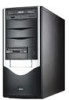
1.3 Front panel features The AP120-E1 chassis displays a black stylish front panel. The power button, LED indicators, optical, and floppy drives are located on the front panel. Flip the front panel I/O - Asus AP120-E1 | User Guide - Page 15
1.4 LED information The AP120-E1 comes with two LED indicators. Refer to the picture for the LED location and the table below for LED description. fan Gigabit LAN port Line Out port AGP expansion slot PCI expansion slots Side cover locking lever Wi-Fi expansion slot ASUS AP120-E1 user guide 1-5 - Asus AP120-E1 | User Guide - Page 16
features The AP120-E1 chassis includes the basic components as shown. 6 1 7 3 2 8 45 11 12 9 10 13 14 1. Power supply 8. FDD bay 2. 9cm chassis fan 9. Detachable HDD cage 3. CPU socket (under the CPU fan) 10. Serial ATA connectors 4. DDR DIMM sockets 11. ASUS P4P800S-E motherboard - Asus AP120-E1 | User Guide - Page 17
Hardware setup Chapter 2 This chapter lists the hardware setup procedures that you have to perform when installing or removing system components. ASUS AP120-E1 user guide - Asus AP120-E1 | User Guide - Page 18
to install You need to install the following components to the AP120-E1 server/workstation. 1. Central processing unit (CPU) 2. Dual Inline Memory Module(s) (DIMMs) 3. Hard disk drive 4. 5.25-inch drive(s) 5. Expansion card(s) Tool You need a Philips (cross) screw driver to install some system - Asus AP120-E1 | User Guide - Page 19
/workstation appear as shown in the following picture. Perform the procedures in the succeeding sections to install the CPU, system memory, disk drives, and expansion cards. ASUS AP120-E1 user guide 2-3 - Asus AP120-E1 | User Guide - Page 20
2.3 Motherboard information The AP120-E1 comes with the ASUS P4P800S-E motherboard that uses the ATX form factor measuring 12 inches x 9.6 inches (30 by circles in the illustration below. Refer to the motherboard user guide for detailed information on the motherboard. 2-4 Chapter 2: Hardware setup - Asus AP120-E1 | User Guide - Page 21
for the Intel® Pentium® 4 Prescott processor in the 478-pin package with 512KB L2 cache. The motherboard supports 800/533/400MHz front side bus (FSB), and allows data transfer rates of up to 6.4GB/s. Note in the socket may bend the pins and severely damage the CPU! ASUS AP120-E1 user guide 2-5 - Asus AP120-E1 | User Guide - Page 22
2.4.2 CPU installation Follow these steps to install a CPU. 1. Locate the 478-pin ZIF socket on the motherboard. 2. Unlock the socket by pressing the lever sideways, then lift it up to a 90°-100° angle. Socket Lever Make sure that the socket lever is lifted up to 90°-100° angle, otherwise the CPU - Asus AP120-E1 | User Guide - Page 23
heatsink and fan following the instructions that came with the heatsink package. ASUS provides an Intel®-certified CPU fan and heatsink assembly as an optional item for your AP120-E1 system. Refer to the " monitoring errors may occur if you fail to plug this connector. ASUS AP120-E1 user guide 2-7 - Asus AP120-E1 | User Guide - Page 24
Data Rate (DDR) Dual Inline Memory Module (DIMM) sockets. These sockets support up to 3GB system memory using 184-pin unbuffered non-ECC PC3200/2700 -E 184-Pin DDR DIMM Sockets Obtain DDR DIMMs only from ASUS qualified vendors to ensure system system stability. The DDR400 Qualified Vendors List (QVL - Asus AP120-E1 | User Guide - Page 25
to remove a DIMM. 1. Simultaneously press the retaining clips outward to unlock the DIMM. Support the DIMM lightly with your fingers when pressing the retaining clips. The DIMM might get damaged when it flips out with extra force. 2. Remove the DIMM from the socket. ASUS AP120-E1 user guide 2-9 - Asus AP120-E1 | User Guide - Page 26
2.6 Installing a hard disk drive The server/workstation system supports one IDE/Serial ATA hard disk drive through a detachable hard disk drive cage. You may purchase a second hard disk drive cage to install an additional - Asus AP120-E1 | User Guide - Page 27
cage to the chassis. Align the HDD cage and bay assembly rails, then carefully push the HDD cage until it is flushed to the chassis. ASUS AP120-E1 user guide 2-11 - Asus AP120-E1 | User Guide - Page 28
drive. 6. Connect a 4-pin power plug from the power supply unit to the power connector at the back of the drive. Refer to the motherboard user guide the correct IDE cable before connecting anIDE cable to the hard disk drive. To install a Serial ATA hard disk drive: 1. Follow steps 1-4 of the - Asus AP120-E1 | User Guide - Page 29
screw for later use. 2. Slightly pull the cover toward the direction of the rear panel until it disengages from the chassis. Set the cover aside. ASUS AP120-E1 user guide 2-13 - Asus AP120-E1 | User Guide - Page 30
3. Press the front panel cover hook inward until it detaches from the chassis hole. 3 4. On the other side of the system, locate three front panel cover hooks. Press the hooks inward until the front panel cover detaches from the chassis. 5. Carefully remove the front panel cover, then set aside. 4 - Asus AP120-E1 | User Guide - Page 31
chassis front panel. Screw holes 3 4 3. Align the optical drive and bay screw holes. 4. Secure the drive with two screws on both sides of the bay. ASUS AP120-E1 user guide 2-15 - Asus AP120-E1 | User Guide - Page 32
5 6 5. Connect a 40-pin IDE cable (from the first optical drive) to the IDE connector on the drive. 6. Connect a 4-pin power plug from the power supply unit to the drive power connector. 7 8 7. Remove the front panel bay cover opposite the drive bay you used by pressing the hooks inward. - Asus AP120-E1 | User Guide - Page 33
slot that you intend to use. Keep the metal bracket screw for later use. 4. Align the card connector with the slot, then press firmly until the 4 card is completely seated on the slot. 5. Secure the card with the metal bracket screw you removed 5 earlier. ASUS AP120-E1 user guide 2-17 - Asus AP120-E1 | User Guide - Page 34
2.9 Removing components You may need to remove previously installed system components when installing or removing other system components, or when replacing a defective component. This section tells how to remove the following components: 1. Floppy disk drive (FDD) 2. System fan 2.9.1 Removing the - Asus AP120-E1 | User Guide - Page 35
the screws for later use. Hold the chassis fan with one hand while removing the chassis fan screws. 3. Remove the chassis fan, then set aside. 3 ASUS AP120-E1 user guide 2-19 - Asus AP120-E1 | User Guide - Page 36
2.10 Connecting cables The AP120-E1 chassis includes the power and signal cables that you need to connect to the Panel cable 8. System fan cable 9. Primary and secondary IDE cable Refer to the motherboard user guide for detailed information on motherboard connectors. 2-20 Chapter 2: Hardware setup - Asus AP120-E1 | User Guide - Page 37
the side cover by following these instructions. 1. Match the side cover hooks to the chassis rail on the side of the chassis. 2 2. Fit the side cover the cover toward the chassis until it fits. 1 3. Slide the cover toward the front until it snaps in place. 3 ASUS AP120-E1 user guide 2-21 - Asus AP120-E1 | User Guide - Page 38
2-22 Chapter 2: Hardware setup - Asus AP120-E1 | User Guide - Page 39
Installation options Chapter 3 This chapter provides information on optional and removable components you may install to or remove from the system. ASUS AP120-E1 user guide - Asus AP120-E1 | User Guide - Page 40
components to the AP120-E1 system. 1. CPU fan and heatsink assembly 2. Second hard disk drive cage 3. Expansion card holder 3.1.1 CPU Locking lever Retention bracket CPU heatsink After installing the CPU, follow these instructions to install the CPU fan and heatsink assembly. 1. Position the CPU - Asus AP120-E1 | User Guide - Page 41
place. 6. Follow steps 2 to 5 to re-install the second retention bracket. 3 4 5 The illustrations are for reference only and may not exactly match the actual component. ASUS AP120-E1 user guide 3-3 - Asus AP120-E1 | User Guide - Page 42
3.1.2 Second hard disk drive cage The second hard disk drive cage accommodates one IDE or Serial ATA hard disk drive. Second hard disk drive cage HDD cage retention base Rails Hooks You need to install the retention base to the chassis before installing the second HDD cage. To install the - Asus AP120-E1 | User Guide - Page 43
with two screws (with metal washers) on both sides of the cage. DO NOT install a hard disk drive to the upper bay of the cage. ASUS AP120-E1 user guide 3-5 - Asus AP120-E1 | User Guide - Page 44
3 4 3. Connect one end of the 7-pin Serial ATA cable to the connector at the back of the drive(s). 4. Align the drive cage and retention base rails, then slightly push the cage until it clicks in place 5 6 5. Connect the other end of the Serial ATA cable to the SATA connectors on the - Asus AP120-E1 | User Guide - Page 45
on the chassis floor. 2 3. Place the retention bracket over the chassis floor screw holes, then secure the bracket with two screws. 4. Turn the chassis upright. ASUS AP120-E1 user guide 3 3-7 - Asus AP120-E1 | User Guide - Page 46
To install the expansion card holder: 1. Insert the expansion card holder locking screw to the retention bracket notch, as shown. 1 2. Turn the expansion card holder 3 upright. 3. Press the locking lever, then insert the hooks to the chassis holes. 2 4. Secure the expansion card holder with one - Asus AP120-E1 | User Guide - Page 47
other card holders are for long PCI cards. 2. Loosen the screw(s) to adjust the card holder forward or sideward until its groove fits the edge of the expansion card. 3. Fasten the card holder screw(s). 4. Follow the same steps in holding other long expansion. 3 ASUS AP120-E1 user guide 3-9 - Asus AP120-E1 | User Guide - Page 48
3-10 Chapter 3: Optional components - Asus AP120-E1 | User Guide - Page 49
the server. It lists the possible causes of the problems and offers solutions. You may refer to this part and try to solve simple problems before calling customer support. The appendix also contains the power supply unit specifications for your reference. Appendix ASUS AP120-E1 user guide A-1 - Asus AP120-E1 | User Guide - Page 50
on the system or the components. These problems only requires simple troubleshooting actions that you can perform by yourself. Problem Action The power LED on the server or DIMMs the system supports. 2. Make sure that the DIMMs are properly installed on the sockets. A-2 Appendix: Troubleshooting - Asus AP120-E1 | User Guide - Page 51
Problem Action The system continuously beeps after it was turned on 1. Check the memory modules and make sure you installed supported DIMMs. 2. Make sure that the DIMMs are properly installed on the sure that you have installed the LAN drivers from the support CD. ASUS AP120-E1 user guide A-3 - Asus AP120-E1 | User Guide - Page 52
% +10% -5% +5% -5% +5% -5% +5% Ripple Max 50mVp-p 120mVp-p 150mVp-p 100mVp-p 100mVp-p 50mVp-p Over-Voltage Protection (OVP) Output Voltage +5V +12V +3.3V Maximum Voltage 6.5V 15.6V 4.3V A-4 Appendix: Troubleshooting
-
 1
1 -
 2
2 -
 3
3 -
 4
4 -
 5
5 -
 6
6 -
 7
7 -
8
-
9
-
10
-
11
-
12
-
13
-
14
-
15
-
16
-
17
-
18
-
19
-
20
-
21
-
22
-
23
-
24
-
25
-
26
-
27
-
28
-
29
-
30
-
31
-
32
-
33
-
34
-
35
-
36
-
37
-
38
-
39
-
40
-
41
-
42
-
43
-
44
-
45
-
46
-
47
-
48
-
49
-
50
-
51
-
52
 |
 |
P4 Pedestal Server/Workstation
800MHz Front Side Bus
User Guide
AP120-E1