Asus AT3IONT-I DELUXE AT3IONT-I Series user's manual
Asus AT3IONT-I DELUXE Manual
 |
View all Asus AT3IONT-I DELUXE manuals
Add to My Manuals
Save this manual to your list of manuals |
Asus AT3IONT-I DELUXE manual content summary:
- Asus AT3IONT-I DELUXE | AT3IONT-I Series user's manual - Page 1
Motherboard AT3IONT-I DELUXE AT3IONT-I - Asus AT3IONT-I DELUXE | AT3IONT-I Series user's manual - Page 2
BUSINESS AND THE LIKE), EVEN IF ASUS HAS BEEN ADVISED OF THE POSSIBILITY OF SUCH DAMAGES ARISING FROM ANY DEFECT OR ERROR IN THIS MANUAL OR PRODUCT. SPECIFICATIONS AND INFORMATION CONTAINED IN THIS MANUAL downloading it from http://support.asus.com/download; or encounter any problems in obtaining - Asus AT3IONT-I DELUXE | AT3IONT-I Series user's manual - Page 3
guide vi AT3IONT-I Series specifications summary viii Chapter 1: Product introduction 1.1 Before you proceed 1-1 1.2 Motherboard overview 1-2 1.2.1 Motherboard layout 1-2 1.2.2 Layout contents 1-2 1.3 Central Processing Unit (CPU 1-3 1.4 System memory 1-3 1.4.1 Overview 1-3 1.4.2 Memory - Asus AT3IONT-I DELUXE | AT3IONT-I Series user's manual - Page 4
2.4.3 Chipset 2-9 2.4.4 Onboard Devices Configuration 2-9 2.4.5 USB Configuration 2-10 2.4.6 PCI PnP 2-11 2.5 Power menu 2-11 2.5.1 Suspend Mode [Auto 2-11 2.5.2 ACPI 2.0 Support [Disabled 2-11 2.5.3 ACPI APIC Support [Enabled 2-11 2.5.4 Control EuP [Disabled 2-12 2.5.5 APM Configuration - Asus AT3IONT-I DELUXE | AT3IONT-I Series user's manual - Page 5
may cause undesired operation. This equipment has been tested and found to comply with the limits for a by turning the equipment off and on, the user is encouraged to try to correct the interference by at ASUS REACH website at http://csr.asus.com/english/REACH.htm. DO NOT throw the motherboard - Asus AT3IONT-I DELUXE | AT3IONT-I Series user's manual - Page 6
are using, contact your local power company. • If the power supply is broken, do not try to fix it by yourself. Contact a qualified service technician or your retailer. Operation safety • Before installing the motherboard and adding devices on it, carefully read all the manuals that came with the - Asus AT3IONT-I DELUXE | AT3IONT-I Series user's manual - Page 7
IMPORTANT: Instructions that you MUST follow to complete a task. NOTE: Tips and additional information to help you complete a task. Where to find more information Refer to the following sources for additional information and for product and software updates. 1. ASUS websites The ASUS website - Asus AT3IONT-I DELUXE | AT3IONT-I Series user's manual - Page 8
AT3IONT-I Series specifications summary CPU Chipset Front Side Bus Memory Graphics Expansion slot Storage Audio LAN USB ASUS special features Integrated Dual-Core Intel® Atom™ 330 processor NVIDIA® ION™ 533 MHz Dual channel memory architecture - 2 x 240-pin DIMM sockets support maximum 4GB - Asus AT3IONT-I DELUXE | AT3IONT-I Series user's manual - Page 9
x User Manual 1 x SATA Power cable* 1 x Remote Controller* 1 x Receiver* 1 x WiFi antenna* 1 x 90W DC adapter* 1 x Power cord* * For AT3IONT-I DELUXE only Drivers ASUS PC Probe II ASUS Update Anti-virus software (OEM version) Mini ITX form factor: 6.75 in x 6.75 in (17.1cm x 17.1cm) *Specifications - Asus AT3IONT-I DELUXE | AT3IONT-I Series user's manual - Page 10
you for buying an ASUS® AT3IONT-I Series motherboard! Before you start installing the motherboard, and hardware devices on it, check the items in your motherboard package. Refer to page ix for the list of accessories. • AT3IONT-I Series motherboards include AT3IONT-I and AT3IONT-I DELUXE two models - Asus AT3IONT-I DELUXE | AT3IONT-I Series user's manual - Page 11
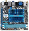
1.2 1.2.1 Motherboard overview Motherboard layout ASUS AT3IONT-I Series motherboards include AT3IONT-I and AT3IONT-I DELUXE two models The layout varies with models. The layout illustrations in this user guide are for AT3IONT-I DELUXE only. Ensure that you install the motherboard into the chassis - Asus AT3IONT-I DELUXE | AT3IONT-I Series user's manual - Page 12
DELUXE 1.3 Central Processing Unit (CPU) The motherboard comes with an onboard Dual-Core Intel® Atom™ 330 processor and a specially designed CPU heatsink. Intel® Atom330 AT3IONT-I SERIES CPU 1.4 System memory 1.4.1 Overview The motherboard comes with two Double Data Rate 3 (DDR3) Dual Inline Memory - Asus AT3IONT-I DELUXE | AT3IONT-I Series user's manual - Page 13
memory, we recommend that you use a maximum of 3GB system memory. • This motherboard does not support DIMMs made up of 256 megabits (Mb) chips or less. AT3IONT-I Series Motherboard support A* B* - •• 1.35V(low voltage) • • - •• - •• - •• 1.5V •• - •• - •• - •• - •• ASUS AT3IONT-I - Asus AT3IONT-I DELUXE | AT3IONT-I Series user's manual - Page 14
1.8V 1.8V 1.8V 1.35V(low voltage) 1.5~1.6V 1.35V(low voltage) 1.5-1.6V 1.5~1.6V 1.5V~1.6V 1.5V 1.3V(low voltage) 1.5V 1.8V 1.65V 1.65V 1.65V 1.60V - - - DIMM support A* B •• (continued on the next page) 1-5 Chapter 1: Product introduction - Asus AT3IONT-I DELUXE | AT3IONT-I Series user's manual - Page 15
-15 - Timing 7-7-7-20 7-7-7-20 7-7-7-20 - Voltage - DIMM support A* B - - •• 9 - •• - - •• - - •• DDR3 1333MHz memory modules run at 1066MHz on AT3IONT-I Series motherboards. SS: Single-sided / DS: Double-sided DIMM support: • A*: Supports one module inserted into either slot as - Asus AT3IONT-I DELUXE | AT3IONT-I Series user's manual - Page 16
Chapter 2 for information on BIOS setup. 2. Assign an IRQ to the card. 3. Install the software drivers for the expansion card. 1.5.3 PCI Express x16 slot This motherboard supports a PCI Express x16 graphics card that complies with the PCI Express specifications. 1-7 Chapter 1: Product introduction - Asus AT3IONT-I DELUXE | AT3IONT-I Series user's manual - Page 17
boot failure! If the steps above do not help, remove the onboard battery and move the jumper again to clear the CMOS RTC RAM data. After clearing the CMOS, reinstall the battery. 1.7 Connectors 1.7.1 Rear panel connectors 1 2 3 4 5 6 78 16 15 14 13 12 11 10 9 ASUS AT3IONT-I Series - Asus AT3IONT-I DELUXE | AT3IONT-I Series user's manual - Page 18
Under Windows® XP, if the Bluetooth Driver item is not displayed on the Support DVD's Drivers screen, follow the steps below: 1. Shut down your computer and switch off the Power Supply Unit (PSU). 2. Switch on the PSU and boot up your computer. 3. Open the Support DVD and click ASUS InstAll. 5. LAN - Asus AT3IONT-I DELUXE | AT3IONT-I Series user's manual - Page 19
HD audio module in the front panel to support 8-channel audio output. 10. RCA Out port (left-channel) (for AT3IONT-I DELUXE only). This port connects a receiver or a 2.0 devices. 16. DC power port (for AT3IONT-I DELUXE only). This port connects to an DC power adapter. ASUS AT3IONT-I Series 1-10 - Asus AT3IONT-I DELUXE | AT3IONT-I Series user's manual - Page 20
• You need to copy RAID driver to other media such as a USB flash disk and load RAID driver during installing Windows® Vista OS with SATA ODD. • For more details on RAID/AHCI, refer to the RAID/AHCI Supplementary Guide included in the folder named Manual in the support DVD. 1-11 Chapter 1: Product - Asus AT3IONT-I DELUXE | AT3IONT-I Series user's manual - Page 21
with USB 2.0 specification that supports up to 480 Mbps connection speed. AT3IONT-I DELUXE USB910 USB78 PIN AT3IONT-I SERIES USB2.0 connectors Never connect a 1394 cable to the USB connectors. Doing so will damage the motherboard! The USB module cable is purchased separately. ASUS AT3IONT - Asus AT3IONT-I DELUXE | AT3IONT-I Series user's manual - Page 22
5. Front panel audio connector (10-1 pin AAFP) This connector is for a chassis-mounted front panel audio I/O module that supports either HD Audio or legacy AC`97 audio standard. Connect one end of the front panel audio I/O module cable to this connector. AT3IONT-I DELUXE GND PRESENCE# SENSE1_RETUR - Asus AT3IONT-I DELUXE | AT3IONT-I Series user's manual - Page 23
6. System panel connector (10-1 pin F_PANEL) This connector supports several chassis-mounted functions. F_PANEL AT3IONT-I DELUXE PWR LED PWR BTN PIN 1 HD_LED RESET GND PWR PLEDPLED+ Reset Ground IDE_LEDIDE_LED+ AT3IONT-I SERIES System panel connector • System power LED (2-pin PLED) This 2-pin - Asus AT3IONT-I DELUXE | AT3IONT-I Series user's manual - Page 24
connector, then install the module to a slot opening at the back of the system chassis. The serial port bracket (COM1) is purchased separately. COM1 PIN 1 AT3IONT-I SERIES Serial port (COM1) connector AT3IONT-I DELUXE 1-15 Chapter 1: Product introduction - Asus AT3IONT-I DELUXE | AT3IONT-I Series user's manual - Page 25
you install Windows® XP Service Pack 3 or later versions / Windows® Vista Service Pack 1 or later versions before installing the drivers for better compatibility and system stability. 1.8.2 Support DVD information The Support DVD that comes with the motherboard package contains the drivers, software - Asus AT3IONT-I DELUXE | AT3IONT-I Series user's manual - Page 26
play the warning wave file. Launching ASUS VideoSecurity 1. Install ASUS VideoSecurity from the motherboard support DVD. 2. To launch the ASUS VideoSecurity from the Windows® desktop, click Start > All Programs > ASUS > ASUS VideoSecurity > ASUS VideoSecurity. The VideoSecurity main screen appears - Asus AT3IONT-I DELUXE | AT3IONT-I Series user's manual - Page 27
VideoSecurity Setting screen To launch the setting screen, click from the main screen. Click for the main screen to refer to the Help file for details on how to setup VideoSecurity. ASUS AT3IONT-I Series 1-18 - Asus AT3IONT-I DELUXE | AT3IONT-I Series user's manual - Page 28
1. Install Home Theater Gate from the motherboard support DVD. 2. To launch Home Theater Gate ,click Start > All Programs > ASUS > ASUS Home Theater Gate > ASUS Home Theater Gate 1.xx.xx. The Home Theater Gate main window appears. Home Theater Gate main window Click to minimize the Home Theater - Asus AT3IONT-I DELUXE | AT3IONT-I Series user's manual - Page 29
, RealPlayer, iTunes • ��V�i�s�it�t�h�e��A�S��U�S���w�e�b��s�it�e��a�t http://support.asus.com/download/download. aspx?SLanguage=en-us for the latest supported type. • Due to Window® XP limitation, you have to install the UDF Reader to recognize the Blu-ray disc. ASUS AT3IONT-I Series 1-20 - Asus AT3IONT-I DELUXE | AT3IONT-I Series user's manual - Page 30
(for AT3IONT-I DELUXE only) Use the remote controller to launch the ASUS Home Theater Gate and start media applications. Connect the IR receiver to the USB 2.0 port 1 or 2 before using the remote controller. Power on/off* Fast rewind Stop Previous track Volume up OK Scroll left Main window Switch - Asus AT3IONT-I DELUXE | AT3IONT-I Series user's manual - Page 31
and update the motherboard BIOS in Windows® environment. • ASUS Update requires an Internet connection either through a network or an Internet Service Provider (ISP). • This utility is available in the support DVD that comes with the motherboard package. Installing ASUS Update To install ASUS Update - Asus AT3IONT-I DELUXE | AT3IONT-I Series user's manual - Page 32
to avail all its features. Updating from a BIOS file a. Select Update BIOS from a file, then click Next. b. Locate the BIOS file from the Open window, then click Open. 3. Follow the onscreen instructions to complete the updating process. 2.1.2 ASUS EZ Flash 2 The ASUS EZ Flash 2 feature allows you - Asus AT3IONT-I DELUXE | AT3IONT-I Series user's manual - Page 33
while updating the BIOS to prevent system boot failure! 2.1.3 ASUS CrashFree BIOS The ASUS CrashFree BIOS is an auto recovery tool that allows you to restore the BIOS file when it fails or gets corrupted during the updating process. You can restore a corrupted BIOS file using the motherboard support - Asus AT3IONT-I DELUXE | AT3IONT-I Series user's manual - Page 34
Use the BIOS Setup program to update the BIOS or configure its parameters. The BIOS screens include navigation keys and brief online help to guide you in using the BIOS Setup program. Entering BIOS Setup at startup To enter BIOS Setup at startup: • Press during the Power-On Self Test (POST - Asus AT3IONT-I DELUXE | AT3IONT-I Series user's manual - Page 35
SATA 1~4 While entering Setup, the BIOS automatically detects the presence of SATA Monitoring). These values are not user-configurable. These items show Not CDROM if you are specifically configuring a CD-ROM the LBA mode if the device supports this mode, and if the device ASUS AT3IONT-I Series 2-5 - Asus AT3IONT-I DELUXE | AT3IONT-I Series user's manual - Page 36
of the general system specifications. The BIOS automatically detects the items in this menu. BIOS Information Displays the auto-detected BIOS information. Processor Displays the auto-detected CPU specification. System Memory Displays the auto-detected system memory. 2.4 Advanced menu The Advanced - Asus AT3IONT-I DELUXE | AT3IONT-I Series user's manual - Page 37
overclock for shader. Configuration options: [Min.=1200] [Max.=2000] Memory Over Voltage [Auto] Manually set memory voltage or set to Auto for safe mode. Press / keys to adjust the value with an increment of 1.02000V. Configuration options: [Auto] [Min.=1.21000V] [Max.=2.47000V] ASUS AT3IONT - Asus AT3IONT-I DELUXE | AT3IONT-I Series user's manual - Page 38
Memory Timings [Auto] Sets the memory timings. Configuration options: [Auto] [Manual] The following items appear only when you set the Memory Timings item to [Manual]. tCL (CAS Latency) [Auto] Configuration options: [Auto] [5] [6] [7] [8] [9] [10 options: [Auto] [4] 2-8 Chapter 2: BIOS information - Asus AT3IONT-I DELUXE | AT3IONT-I Series user's manual - Page 39
[PCIE LAN item is set to Enabled. Configuration options: [Disabled] [Enabled] The following two items appear only on AT3IONT-I DELUXE motherboard. Onboard Bluetooth [Enabled] Allows you to enable or disable the onboard Bluetooth controller. Configuration options: [Enabled] [Disabled] ASUS AT3IONT - Asus AT3IONT-I DELUXE | AT3IONT-I Series user's manual - Page 40
legacy mode is enabled. If no USB device is detected, the legacy USB support is disabled. Configuration options: [Disabled] [Enabled] [Auto] USB 2.0 Allows you to set the maximum time that the BIOS waits for the USB storage device to initialize. Configuration options: [10 Sec] [20 Sec] [30 Sec] [40 - Asus AT3IONT-I DELUXE | AT3IONT-I Series user's manual - Page 41
memory BIOS power than in the S1 state. When signaled by a wake Power Interface (ACPI) support in the Application-Specific Integrated Circuit (ASIC). When set to Enabled, the ACPI APIC table pointer is included in the RSDT pointer list. Configuration options: [Disabled] [Enabled] ASUS AT3IONT - Asus AT3IONT-I DELUXE | AT3IONT-I Series user's manual - Page 42
wake event. This feature requires an ATX power supply that provides at least 1A on the +5VSB lead. Configuration options: [Disabled] [Enabled] Power On By PS/2 Keyboard [Disabled] Allows you to use specific power fan speeds in rotations per minute (RPM). If the fan is not connected to the motherboard - Asus AT3IONT-I DELUXE | AT3IONT-I Series user's manual - Page 43
when ASUS Logo appears. • To access Windows® OS in Safe Mode, do any of the following: • Press when ASUS Logo appears. • Press after POST. 2.6.2 Boot Settings Configuration Quick Boot [Enabled] Enabling this item allows the BIOS to skip some power on self tests (POST) while - Asus AT3IONT-I DELUXE | AT3IONT-I Series user's manual - Page 44
ASUS MyLogo2™ feature. AddOn ROM Display Mode [Force BIOS] Sets the display mode for option ROM. Configuration options: [Force BIOS] [Keep Current] Bootup Num-Lock [On] Allows you to select the power to allow you to change other security settings. User Access Level [Full Access] This item allows you - Asus AT3IONT-I DELUXE | AT3IONT-I Series user's manual - Page 45
> to display the sub-menu. Main Advanced Power BIOS SETUP UTILITY Boot Tools Exit ASUS EZ Flash 2 Express Gate Enter OS Timer Reset User Data AI NET2 [Auto] [10 Seconds] [No] Press ENTER to run the utility to select and update BIOS. This utility supports 1.FAT 12/16/32(r/w) 2.NTFS(read only - Asus AT3IONT-I DELUXE | AT3IONT-I Series user's manual - Page 46
cable [Disabled] Enables or disables checking of the Realtek LAN cable during the Power-On Self‑Test (POST). Configuration options: [Disabled] [Enabled] 2.8 Exit menu The Exit menu items allow you to load the optimal or failsafe default values for the BIOS items, and save or discard your changes - Asus AT3IONT-I DELUXE | AT3IONT-I Series user's manual - Page 47
Harkort Str. 21-23, D-40880 Ratingen, Germany Fax +49-2102-959911 Web site www.asus.de Online contact www.asus.de/sales Technical Support Telephone (Component) Telephone (System/Notebook/Eee/LCD) Support Fax Online support +49-1805-010923* +49-1805-010920* +49-2102-9599-11 - Asus AT3IONT-I DELUXE | AT3IONT-I Series user's manual - Page 48
(a) Responsible Party Name: Asus Computer International Address: 800 Corporate Way, Fremont, CA 94539. Phone/Fax No: (510)739-3777/(510)608-4555 hereby declares that the product Product Name : Motherboard Model Number :AT3IONT-I DELUXE Conforms to the following specifications: FCC Part 15, Subpart
-
 1
1 -
 2
2 -
 3
3 -
 4
4 -
 5
5 -
 6
6 -
 7
7 -
8
-
9
-
10
-
11
-
12
-
13
-
14
-
15
-
16
-
17
-
18
-
19
-
20
-
21
-
22
-
23
-
24
-
25
-
26
-
27
-
28
-
29
-
30
-
31
-
32
-
33
-
34
-
35
-
36
-
37
-
38
-
39
-
40
-
41
-
42
-
43
-
44
-
45
-
46
-
47
-
48
 |
 |

Motherboard
AT3IONT-I DELUXE
AT3IONT-I