Asus F1A55-M LX3 PLUS R2.0 F1A55-M LX3 PLUS R2.0 User's Manual - Page 33
F1A55-M LX3 PLUS R2.0 ATX power connectors
 |
View all Asus F1A55-M LX3 PLUS R2.0 manuals
Add to My Manuals
Save this manual to your list of manuals |
Page 33 highlights
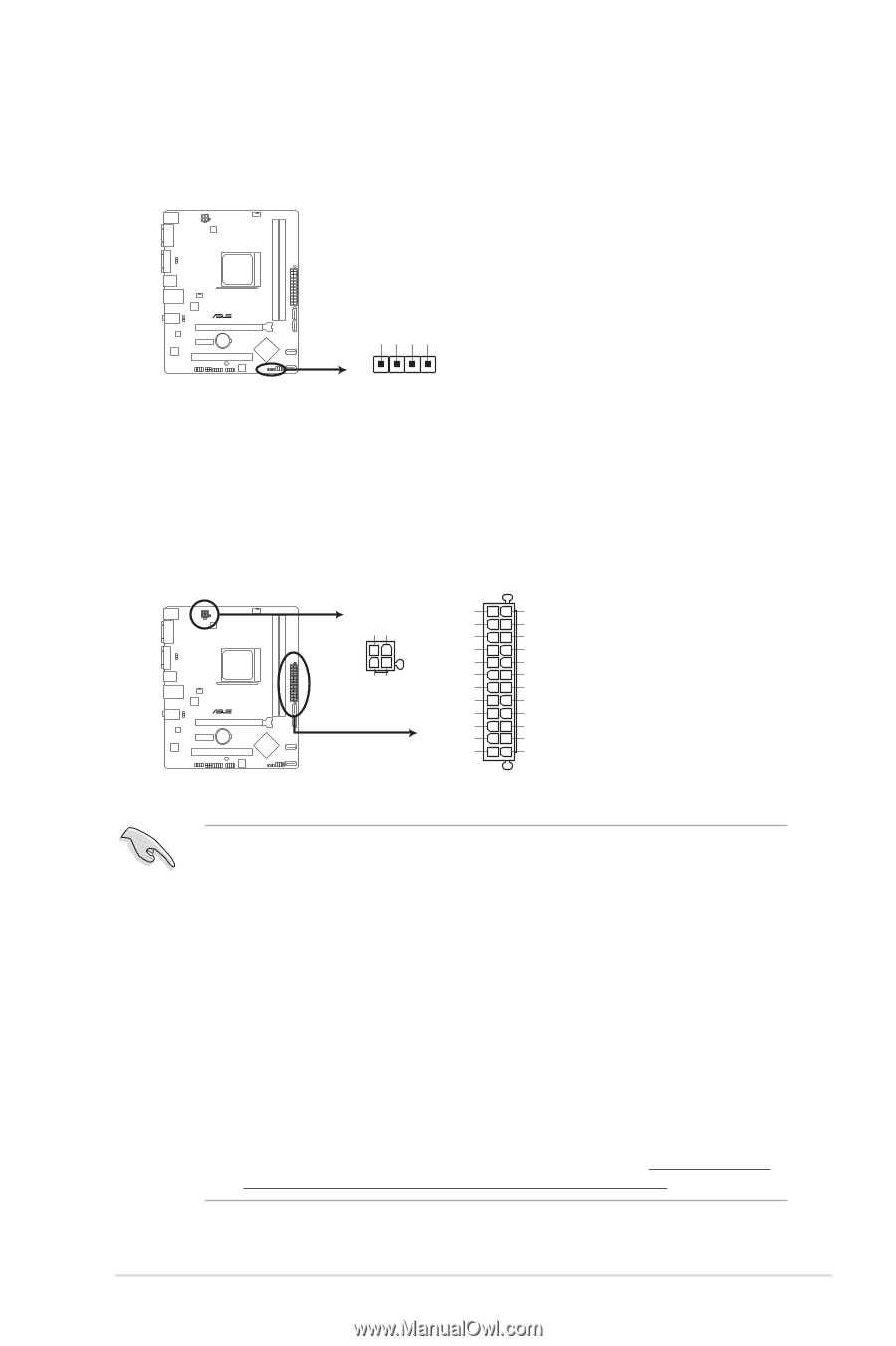
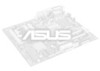
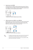
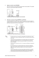
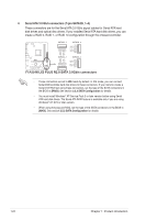
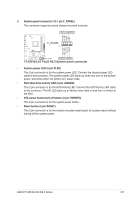
2. Speaker connector (4-pin SPEAKER) This 4-pin connector is for the chassis-mounted system warning speaker. The speaker allows you to hear system beeps and warnings. SPEAKER +5V GND GND Speaker Out F1A55-M LX3 PLUS R2.0 PIN 1 F1A55-M LX3 PLUS R2.0 Speaker out connector 3. ATX power connectors (24-pin EATXPWR, 4-pin ATX12V) These connectors are for an ATX power supply. The plugs from the power supply are designed to fit these connectors in only one orientation. Find the proper orientation and push down firmly until the connectors completely fit. ATX12V EATXPWR F1A55-M LX3 PLUS R2.0 GND GND +3 Volts GND +12 Volts +5 Volts +12 Volts PIN 1 +5V Standby +5 Volts +5 Volts Power OK -5 Volts GND GND +12V DC +12V DC +5 Volts GND GND GND +5 Volts PSON# GND GND +3 Volts -12 Volts +3 Volts +3 Volts PIN 1 F1A55-M LX3 PLUS R2.0 ATX power connectors • We recommend that you use an ATX 12V Specification 2.0‑compliant power supply unit (PSU) with a minimum of 300W power rating. This PSU type has 24-pin and 4-pin power plugs. • If you intend to use a PSU with 20-pin and 4-pin power plugs, ensure that the 20-pin power plug can provide at least 15 A on +12 V and that the PSU has a minimum power rating of 300W. The system may become unstable or may not boot up if the power is inadequate. • DO NOT forget to connect the 4-pin ATX +12V power plug. Otherwise, the system will not boot up. • We recommend that you use a PSU with higher power output when configuring a system with more power-consuming devices or when you intend to install additional devices. The system may become unstable or may not boot up if the power is inadequate. • If you are uncertain about the minimum power supply requirement for your system, refer to the Recommended Power Supply Wattage Calculator at http://support.asus. com/PowerSupplyCalculator/PSCalculator.aspx?SLanguage=en-us for details. ASUS F1A55-M LX3 R2.0 Series 1-23
-
 1
1 -
2
-
3
-
4
-
5
-
6
-
7
-
8
-
9
-
10
-
11
-
12
-
13
-
14
-
15
-
16
-
17
-
18
-
19
-
20
-
21
-
22
-
23
-
24
-
25
-
26
-
27
-
 28
28 -
 29
29 -
 30
30 -
 31
31 -
 32
32 -
 33
33 -
 34
34 -
 35
35 -
 36
36 -
 37
37 -
 38
38 -
39
-
40
-
41
-
42
-
43
-
44
-
45
-
46
-
47
-
48
-
49
-
50
-
51
-
52
-
53
-
54
-
55
-
56
-
57
-
58
-
59
-
60
-
61
-
62
-
63
-
64
-
65
-
66
-
67
-
68
-
69
 |
 |