Asus F1A55-M LX3 PLUS R2.0 F1A55-M LX3 PLUS R2.0 User's Manual - Page 35
System power LED 2-pin PLED
 |
View all Asus F1A55-M LX3 PLUS R2.0 manuals
Add to My Manuals
Save this manual to your list of manuals |
Page 35 highlights
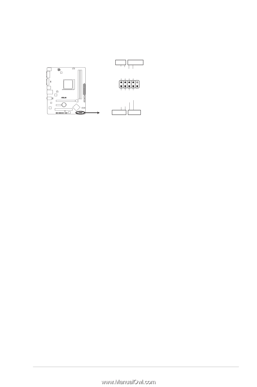
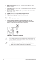
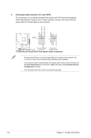
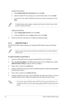
5. System panel connector (10-1 pin F_PANEL) This connector supports several chassis-mounted functions. PLED PWRBTN PLED+ PLEDPWR GND F1A55-M LX3 PLUS R2.0 F_PANEL PIN 1 HD_LED+ HD_LED- Ground Reset +HDLED RESET F1A55-M LX3 PLUS R2.0 System panel connector • System power LED (2-pin PLED) This 2-pin connector is for the system power LED. Connect the chassis power LED cable to this connector. The system power LED lights up when you turn on the system power, and blinks when the system is in sleep mode. • Hard disk drive activity LED (2-pin +HDLED) This 2-pin connector is for the HDD Activity LED. Connect the HDD Activity LED cable to this connector. The HD LED lights up or flashes when data is read from or written to the HDD. • ATX power button/soft-off button (2-pin PWRBTN) This 2-pin connector is for the system power button. • Reset button (2-pin RESET) This 2-pin connector is for the chassis-mounted reset button for system reboot without turning off the system power. ASUS F1A55-M LX3 R2.0 Series 1-25
-
 1
1 -
2
-
3
-
4
-
5
-
6
-
7
-
8
-
9
-
10
-
11
-
12
-
13
-
14
-
15
-
16
-
17
-
18
-
19
-
20
-
21
-
22
-
23
-
24
-
25
-
26
-
27
-
28
-
29
-
 30
30 -
 31
31 -
 32
32 -
 33
33 -
 34
34 -
 35
35 -
 36
36 -
 37
37 -
 38
38 -
 39
39 -
 40
40 -
41
-
42
-
43
-
44
-
45
-
46
-
47
-
48
-
49
-
50
-
51
-
52
-
53
-
54
-
55
-
56
-
57
-
58
-
59
-
60
-
61
-
62
-
63
-
64
-
65
-
66
-
67
-
68
-
69
 |
 |