Asus F1A75-M PRO User Manual
Asus F1A75-M PRO Manual
 |
View all Asus F1A75-M PRO manuals
Add to My Manuals
Save this manual to your list of manuals |
Asus F1A75-M PRO manual content summary:
- Asus F1A75-M PRO | User Manual - Page 1
F1A75-M PRO Motherboard - Asus F1A75-M PRO | User Manual - Page 2
of ASUSTeK Computer Inc. ("ASUS"). Product warranty or service will not be extended if 2011, either (1) for free by downloading it from http://support.asus.com/download; or (2) for the cost of Software licenses. If however you encounter any problems in obtaining the full corresponding source code we - Asus F1A75-M PRO | User Manual - Page 3
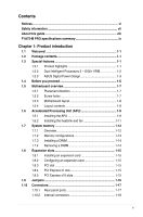
vii About this guide viii F1A75-M PRO specifications summary ix Chapter 1: Product introduction 1.1 Welcome 1-1 1.2 Package contents 1-1 1.3 Special features 1-1 1.3.1 Product highlights 1-1 1.3.2 Dual Intelligent Processors 2 - DIGI+ VRM 1-2 1.3.3 ASUS Digital Power Design 1-3 1.4 Before - Asus F1A75-M PRO | User Manual - Page 4
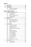
2-3 2.1.4 ASUS BIOS Updater 2-4 2.2 BIOS setup program 2-7 2.3 Main menu 2-11 2.3.1 System Language [English 2-11 2.3.2 System Date [Day xx/xx/xxxx 2-11 2.3.3 System Time [xx:xx:xx 2-11 2.3.4 Security 2-11 2.4 Ai Tweaker menu 2-13 2.4.1 Ai Overclock Tuner [Auto 2-14 2.4.2 Memory Frequency - Asus F1A75-M PRO | User Manual - Page 5
2.7.3 Wait for 'F1' If Error [Enabled 2-25 2.7.4 Option ROM Messages [Force BIOS 2-26 2.7.5 Setup Mode [EZ Mode 2-26 2.7.6 Boot Option Priorities 2-26 2.7.7 Boot Override 2-26 2.8 Tools menu 2-27 2.8.1 ASUS EZ Flash 2 Utility 2-27 2.8.2 ASUS O.C. Profile 2-27 2.8.3 ASUS SPD Information 2-27 - Asus F1A75-M PRO | User Manual - Page 6
and, if not installed and used in accordance with manufacturer's instructions, may cause harmful interference to radio communications. However, there is digital apparatus complies with Canadian ICES-003. ASUS Recycling/Takeback Services ASUS recycling and takeback programs come from our commitment - Asus F1A75-M PRO | User Manual - Page 7
are using, contact your local power company. • If the power supply is broken, do not try to fix it by yourself. Contact a qualified service technician or your retailer. Operation safety • Before installing the motherboard and adding devices on it, carefully read all the manuals that came with the - Asus F1A75-M PRO | User Manual - Page 8
need when installing and configuring the motherboard. How this guide is organized This guide contains the following parts: • Chapter 1: Product introduction This chapter describes the features of the motherboard and the new technology it supports. • Chapter 2: BIOS information This chapter tells how - Asus F1A75-M PRO | User Manual - Page 9
Radeon™ HD 6000 series graphics, up to 4 CPU cores, FM1 package AMD® Turbo Core Technology 2.0 support * The AMD® Turbo Core Technology 2.0 support depends on the APU types. ** Refer to www.asus.com for the AMD® CPU support list AMD® A75 FCH (Hudson D3) Dual-channel memory architecture 4 x 240 - Asus F1A75-M PRO | User Manual - Page 10
F1A75-M PRO specifications summary Audio USB ASUS unique features Special features Back Panel I/O ports ALC892 8-channel High Definition Audio CODEC - Supports Jack-Detection, Multi-Streaming, and Front Panel Jack-Retasking - Supports S/PDIF out interface at the back I/O AMD® A75 FCH - Asus F1A75-M PRO | User Manual - Page 11
F1A75-M PRO specifications summary ASUS exclusive overclocking features Internal I/O connectors / buttons / switches BIOS Accessories Support DVD Form factor Intelligent overclocking tools: - TPU Switch - Auto Tuning Precision Tweaker 2 - vCore: Adjustable CPU voltage at 0.00625V increment - - Asus F1A75-M PRO | User Manual - Page 12
xii - Asus F1A75-M PRO | User Manual - Page 13
DVD Documentations ASUS F1A75-M PRO motherboard 2 x Serial ATA 6.0Gb/s cables 1 x Q-Shield ASUS motherboard Support DVD User Manual If any of the above items is damaged or missing, contact your retailer. 1.3 1.3.1 Special features Product highlights AMD® A- & E2- series accelerated processors - Asus F1A75-M PRO | User Manual - Page 14
1.3.2 AMD® A75 FCH (Hudson D3) Chipset AMD® A75 FCH (Hudson D3) is designed to support up to 5GT/s interface speed and PCI Express™ 2.0 x 16 (at x4 speed) graphics. It supports 6 x SATA 6Gb/s ports and 4 x USB 3.0 Ports. ATI® CrossFireX™ Technology ATI's CrossFireX™ boosts image quality along with - Asus F1A75-M PRO | User Manual - Page 15
! MemOK! guickly ensures memory boot compatibility. This remarkable memory rescue tool requires a mere push of the button to patch memory issues. MemOK! determines failsafe settings and dramatically improves your system boot success. Get your system up and running in no time. ASUS F1A75-M PRO 1-3 - Asus F1A75-M PRO | User Manual - Page 16
and the motherboard from damage caused by power surges from switching power supply unit (PSU). AI Suite II With its fast user-friendly interface, ASUS AI Suite II consolidates all the exclusive ASUS features into one simple to use software package. It allows you to supervise overclocking, energy - Asus F1A75-M PRO | User Manual - Page 17
you to restore a corrupted BIOS file using the bundled support DVD or a USB flash disk that contains the BIOS file. C.P.R. (CPU Parameter Recall) The BIOS C.P.R. feature automatically restores the CPU default settings when the system hangs due to overclocking failure. C.P.R. eliminates the need - Asus F1A75-M PRO | User Manual - Page 18
before you install motherboard components or change any motherboard settings. • Unplug the power cord from the wall socket before touching any component. • Before handling components, use a grounded wrist strap or touch a safely grounded object or a metal object, such as the power supply case, to - Asus F1A75-M PRO | User Manual - Page 19
indicated in the image below. 1.5.2 Screw holes Place eight screws into the holes indicated by circles to secure the motherboard to the chassis. DO NOT overtighten the screws! Doing so can damage the motherboard. Place this side towards the rear of the chassis. F1A75-M PRO ASUS F1A75-M PRO 1-7 - Asus F1A75-M PRO | User Manual - Page 20
8111E Super I/O PWR_FAN Lithium Cell CMOS Power PCIEX16_1 F1A75-M PRO PCIEX1_1 TPU PCI1 AMD® A75 1 SB_PWR 11 12 SATA6G_2 SATA6G_4 SATA6G_6 SATA6G_1 SATA6G_3 SATA6G_5 ALC 892 AAFP SPDIF_OUT PCIEX16_2 USB78 COM1 USB910 USB34 USB56 USB3_56 CLRTC 32Mb BIOS PANEL 13 19 18 17 16 15 - Asus F1A75-M PRO | User Manual - Page 21
1.6.1 Installing the APU To install a APU: 1. Locate the FM1 socket on the motherboard. F1A75-M PRO F1A75-M PRO processor socket FM1 2. Press the lever sideways to unlock the socket, then lift it up to a 90°-100° angle. Socket lever Ensure that the socket lever is lifted up to a 90°-100° angle - Asus F1A75-M PRO | User Manual - Page 22
can also refer to section 1.6.2 Installing heatsink and fan for instructions. 7. Connect the CPU fan cable to the CPU_FAN connector on the motherboard. CPU_FAN F1A75-M PRO F1A75-M PRO CPU fan connector DO NOT forget to connect the CPU fan connector! Hardware monitoring errors can occur if you fail - Asus F1A75-M PRO | User Manual - Page 23
should come with installation instructions for the CPU, heatsink, and the retention mechanism. If the instructions in this section do not match the CPU documentation, follow the latter. 2. Attach one end of the retention bracket to the retention module base. 1 2 3 4 5 ASUS F1A75-M PRO 1-11 - Asus F1A75-M PRO | User Manual - Page 24
are developed for better performance with less power consumption. The figure illustrates the location of the DDR3 DIMM sockets: DIMM_A1 DIMM_A2 DIMM_B1 DIMM_B2 F1A75-M PRO Channel Channel A Channel B F1A75-M PRO 240-pin DDR3 DIMM sockets Sockets DIMM_A1 and DIMM_A2 DIMM_B1 and DIMM_B2 1-12 - Asus F1A75-M PRO | User Manual - Page 25
, refer to section 2.4 Ai Tweaker menu for manual memory frequency adjustment. • For system stability, use a more efficient memory cooling system to support a full memory load (4 DIMMs) or overclocking condition. Visit the ASUS website at www.asus.com for the latest QVL. ASUS F1A75-M PRO 1-13 - Asus F1A75-M PRO | User Manual - Page 26
Installing a DIMM Unplug the power supply before adding or removing DIMMs or other system components. Failure to do so can cause severe damage to both the motherboard and the components. 1. Press the retaining clips outward to unlock a DIMM socket. 2. Align a DIMM on the socket such that the notch - Asus F1A75-M PRO | User Manual - Page 27
slot This motherboard supports PCI Express x1 network cards, SCSI cards, and other cards that comply with the PCI Express specifications. 1.8.5 PCI Express x16 slots This motherboard supports two PCI Express x16 graphics cards that comply with the PCI Express specifications. ASUS F1A75-M PRO 1-15 - Asus F1A75-M PRO | User Manual - Page 28
can clear the CMOS memory of date, time, and system setup parameters by erasing the CMOS RTC RAM data. The onboard button cell battery powers the RAM data in CMOS, which include system setup information such as system passwords. F1A75-M PRO CLRTC 12 23 Normal (Default) F1A75-M PRO Clear RTC RAM - Asus F1A75-M PRO | User Manual - Page 29
for a VGA monitor or other VGA-compatible devices. 4. LAN (RJ-45) port. This port allows Gigabit connection to a Local Area Network (LAN) through a network hub. LAN port LED indications Activity/Link port connects to the side speakers in the 8-channel audio configuration. ASUS F1A75-M PRO 1-17 - Asus F1A75-M PRO | User Manual - Page 30
2.0 ports 1 and 2. These two 4-pin Universal Serial Bus (USB) ports are for USB 2.0/1.1 devices. 12. USB 3.0 ports 1 and 2. These two 9-pin Universal Serial Bus (USB) ports are for USB 3.0 devices. 13. DVI-D port. This port is for any DVI-D compatible device. DVI-D can't be converted to output RGB - Asus F1A75-M PRO | User Manual - Page 31
maximum 2A (24 W) fan power. • Only the CPU_FAN and CHA_FAN1/2 connectors support the ASUS Fan Xpert feature. • If you install two VGA cards, we recommend that you plug the rear chassis fan cable to the motherboard connector labeled CHA_FAN1/2 for better thermal environment. ASUS F1A75-M PRO 1-19 - Asus F1A75-M PRO | User Manual - Page 32
become unstable or may not boot up if the power is inadequate. • If you are uncertain about the minimum power supply requirement for your system, refer to the Recommended Power Supply Wattage Calculator at http://support.asus. com/PowerSupplyCalculator/PSCalculator.aspx?SLanguage=en-us for details - Asus F1A75-M PRO | User Manual - Page 33
of the SATA connectors in the BIOS to [RAID]. See section 2.5.2 SATA Configuration for details. • You must install Windows® XP Service Pack 3 or later version before . COM1 PIN 1 F1A75-M PRO F1A75-M PRO Serial port (COM1) connector The COM module is purchased separately. ASUS F1A75-M PRO 1-21 - Asus F1A75-M PRO | User Manual - Page 34
) This connector supports several chassis-mounted functions. PLED SPEAKER PLED+ PLED+5V Ground Ground Speaker PANEL PIN 1 IDE_LED+ IDE_LED- PWR Ground Reset Ground F1A75-M PRO IDE_LED PWRSW RESET * Requires an ATX power supply F1A75-M PRO System panel connector • System power LED (2-pin - Asus F1A75-M PRO | User Manual - Page 35
audio capability. • If you want to connect a high definition front panel audio module to this connector, set the Front Panel Type item in the BIOS to [HD]. See section 2.5.5 Onboard Devices Configuration for details. • The front panel audio I/O module is purchased separately. ASUS F1A75-M PRO 1-23 - Asus F1A75-M PRO | User Manual - Page 36
to the rear side of the chassis. If your chassis support customized front panel installation, with ASUS USB 3.0 header, you can have a front panel USB 3.0 solution. USB3_56 F1A75-M PRO F1A75-M PRO USB3.0 Front panel connector The USB 3.0 module is purchased separately. 1-24 Chapter 1: Product - Asus F1A75-M PRO | User Manual - Page 37
load BIOS default settings. A message will appear during POST reminding you that the BIOS has been restored to its default settings. • We recommend that you download and update to the latest BIOS version from the ASUS website at www.asus.com after using the MemOK! function. ASUS F1A75-M PRO 1-25 - Asus F1A75-M PRO | User Manual - Page 38
2. TPU switch This switch allows you to enable or disable the TPU function. TPU F1A75-M PRO F1A75-M PRO TPU switch 3. EPU switch This switch allows you to enable or disable the EPU function. EPU F1A75-M PRO F1A75-M PRO EPU switch 1-26 Chapter 1: Product introduction - Asus F1A75-M PRO | User Manual - Page 39
motherboard booting process. If an error is found , the LED next to the error device will continue lighting until the problem is solved. This user-friendly design provides an intuitional way to locate the root problem within a second. F1A75-M PRO DRAM LED F1A75-M PRO DRAM LED ASUS F1A75-M PRO - Asus F1A75-M PRO | User Manual - Page 40
3. TPU LED The TPU LED lights when the TPU switch is turned to Enable. ELED730 F1A75-M PRO F1A75-M PRO TPU LED 4. EPU LED The EPU LED lights when the EPU switch is turned to Enable. ELED740 F1A75-M PRO F1A75-M PRO EPU LED 1-28 Chapter 1: Product introduction - Asus F1A75-M PRO | User Manual - Page 41
only. Click an icon to display Support DVD/ motherboard information Click an item to install If Autorun is NOT enabled on your computer, browse the contents of the Support DVD to locate the file ASSETUP.EXE from the BIN folder. Double-click the ASSETUP.EXE to run the DVD. ASUS F1A75-M PRO 1-29 - Asus F1A75-M PRO | User Manual - Page 42
1-30 Chapter 1: Product introduction - Asus F1A75-M PRO | User Manual - Page 43
and update the motherboard BIOS in Windows® environment. • ASUS Update requires an Internet connection either through a network or an Internet Service Provider (ISP). • This utility is available in the support DVD that comes with the motherboard package. Installing ASUS Update To install ASUS Update - Asus F1A75-M PRO | User Manual - Page 44
EZ Flash 2: 1. Insert the USB flash disk that contains the latest BIOS file to the USB port. 2. Enter the Advanced Mode of the BIOS setup program. Go to the Tool menu to select ASUS EZ Flash Utility and press to enable it. ASUS EZ Flash 2 Utility V01.02 Flash Info MODEL: F1A75-M PRO File - Asus F1A75-M PRO | User Manual - Page 45
the motherboard support DVD or a USB flash drive that contains the updated BIOS file. • Before using this utility, rename the BIOS file in the removable device into F1A75MP.ROM. • The BIOS file in the support DVD may not be the latest version. Download the latest BIOS file from the ASUS website - Asus F1A75-M PRO | User Manual - Page 46
shown. Before updating BIOS 1. Prepare the motherboard support DVD and a USB flash drive in FAT32/16 format and single partition. 2. Download the latest BIOS file and BIOS Updater from the ASUS website at http://support.asus.com and save them on the USB flash drive. NTFS is not supported under DOS - Asus F1A75-M PRO | User Manual - Page 47
for the extension. 2. The BIOS Updater backup screen appears indicating the BIOS backup process. When BIOS backup is done, press any key to return to the DOS prompt. ASUSTek BIOS Updater for DOS V1.07 Current ROM BOARD: F1A75-M PRO VER: 0301 DATE: 05/16/2011 Update ROM BOARD: Unknown VER: Unknown - Asus F1A75-M PRO | User Manual - Page 48
default settings to ensure system compatibility and stability. Select the Load Optimized Defaults item under the Exit menu. Refer to section 2.9 Exit menu for details. • Ensure to connect all SATA hard disk drives after updating the BIOS file if you have disconnected them. 2-6 ASUS F1A75-M PRO - Asus F1A75-M PRO | User Manual - Page 49
BIOS setup program Use the BIOS Setup program to update the BIOS or configure its parameters. The BIOS screens include navigation keys and brief online help to guide you in using the BIOS Setup program. Entering BIOS Setup at startup To enter BIOS Setup at startup: • Press during the Power - Asus F1A75-M PRO | User Manual - Page 50
output, CPU/chassis/power fan speed Exits the BIOS setup program without saving the changes, saves the changes and resets the system, or enters the Advanced Mode EFI BIOS Utility - EZ Mode Friday [10/08/2010] F1A75-M PRO BIOS Version : 0301 CPU Type : AMD Engineering Sample Total Memory : 1024 - Asus F1A75-M PRO | User Manual - Page 51
then select ASUS EZ Mode. Back button Menu items Menu bar Configuration fields EFI BIOS Utility - Asmedia USB 3.0 →←: Select Screen ↑↓: Select Item Enter: Select +/-: Change Opt. F1: overclocking settings For changing the advanced system settings For displaying the system temperature, power - Asus F1A75-M PRO | User Manual - Page 52
button This button appears when entering a submenu. Press or use the USB mouse to click this button to return to the previous menu screen. Submenu corner of the menu screen are the navigation keys for the BIOS setup program. Use the navigation keys to select items in the 2-10 ASUS F1A75-M PRO - Asus F1A75-M PRO | User Manual - Page 53
BIOS Information BIOS Version Build Date 0301 x64 05/16/2011 CPU Information AMD Engineering Sample Speed 2400 MHz Memory Information Total Memory . 2.3.1 System Language [English] Allows you to choose the BIOS language version from the options. Configuration options: [English] 2.3.2 - Asus F1A75-M PRO | User Manual - Page 54
for accessing the system. Otherwise, you might be able to see or change only selected fields in the BIOS setup program. To set an administrator password: 1. Select the Administrator Password item and press . User Password item on top of the screen shows Not Installed. 2-12 ASUS F1A75-M PRO - Asus F1A75-M PRO | User Manual - Page 55
on the CPU and DIMM model you installed on the motherboard. EFI BIOS Utility - Advanced Mode Exit Main Ai Tweaker Advanced Monitor Boot Tool Target CPU Speed: XXXXMHz Target DRAM Speed: XXXXMHz Ai Overclock Tuner Auto Memory Frequency Auto APU Multiplier Auto EPU Power Saving Mode - Asus F1A75-M PRO | User Manual - Page 56
options: [Disabled] [Enabled] EPU Setting [Auto] This item appears only when The EPU Power Saving Mode is set to [Enabled] and allows you to set power saving mode. Configuration options: [Auto] [Light Power Saving Mode] [Medium Power Saving Mode] [Max Power Saving Mode] 2-14 ASUS F1A75-M PRO - Asus F1A75-M PRO | User Manual - Page 57
overclocks the frequency and voltage of CPU and DRAM for enhancing the system performance. Press and select OK to start automatic overclocking Manual Mode] To set the voltage manually. CPU Offset Mode Sign [+] This item appears only when you set the CPU when you set the CPU Voltage item to [ - Asus F1A75-M PRO | User Manual - Page 58
] [High] [Extreme] CPU Current Capability [100%] This item provides wider total power range for overclocking. A higher value brings a wider total power range and extends the overclocking frequency range simultaneously. Configuration options: [100%] [110%] [120%] [130%] [140%] 2-16 ASUS F1A75-M PRO - Asus F1A75-M PRO | User Manual - Page 59
Capability [100%] This item provides wider total power range for overclocking. A higher value brings a wider total power range and extends the overclocking frequency range simultaneously. Configuration options: [100%] [110%] [120%] [130%] CPU Power Phase Control [Standard] Phase number is the - Asus F1A75-M PRO | User Manual - Page 60
. Configuration options: [Disabled] [Auto] AMD PowerNow function [Enabled] Enables or disables the AMD PowerNow function. Configuration options: [Enabled] [Disabled] SVM [Enabled] Enables or disables CPU virtualization. Configuration options: [Disabled] [Enabled] 2-18 ASUS F1A75-M PRO - Asus F1A75-M PRO | User Manual - Page 61
ports can only be used under OS with driver installed. Set to [IDE] instead of [AHCI USB device is detected, the item shows None. Legacy USB Support [Enabled] [Enabled] Enables the support for USB devices on legacy operating systems (OS). [Disabled] The USB devices can be used only for the BIOS - Asus F1A75-M PRO | User Manual - Page 62
or disables the Internal Graphics Device Multi-Monitor support for add-on VGA devices. And the memory size of Internal Graphics Device will keep memory reserved. Configuration options: [Disabled] [Enabled] for SPDIF audio output. [HDMI] Sets to [HDMI] for HDMI audio output. 2-20 ASUS F1A75-M PRO - Asus F1A75-M PRO | User Manual - Page 63
power supply that provides at least 1A on the +5VSB lead. Power On By PS/2 Mouse [Disabled] [Disabled] Disables the Power On by a PS/2 mouse. [Enabled] Enables the Power On by a PS/2 mouse. This feature requires an ATX power supply that provides at least 1A on the +5VSB lead. Chapter 2: BIOS - Asus F1A75-M PRO | User Manual - Page 64
.000 V Anti Surge Support Enabled Boot CPU Temperature Tool →←: Select Screen ↑↓: Select Item Enter: Select +/-: Change Opt. F1: General Help F2: Previous Values F5: Optimized Defaults F10: Save ESC: Exit Version 2.00.1201. Copyright (C) 2011 American Megatrends, Inc. 2-22 ASUS F1A75-M PRO - Asus F1A75-M PRO | User Manual - Page 65
the CPU / chassis / Power fan speeds in rotations per minute (RPM). If the fan is not connected to the motherboard, the CPU fan speed. [Manual] Sets to [Manual] to assign detailed fan speed control parameters. The following four items appear only when you set CPU Fan Profile to [Manual]. CPU - Asus F1A75-M PRO | User Manual - Page 66
Fan Profile to [Manual]. Chassis Upper Temperature [70ºC] Use the and keys to adjust the upper limit of the CPU temperature. The values Support [Enabled] This item allows you to enable or disable the Anti Surge function. Configuration options: [Disabled] [Enabled] 2-24 ASUS F1A75-M PRO - Asus F1A75-M PRO | User Manual - Page 67
For 'F1' If Error Enabled Option ROM Messages Force BIOS Setup power-on state of the NumLock to [Off]. 2.7.2 [Enabled] [Disabled] Full Screen Logo [Enabled] Enables the full screen logo display feature. Disables the full screen logo display feature. Set this item to [Enabled] to use the ASUS - Asus F1A75-M PRO | User Manual - Page 68
Sets Advanced Mode as the default screen for entering the BIOS setup program. [EZ Mode] Sets EZ Mode as the default screen for entering the BIOS setup program. 2.7.6 Boot Option Priorities These items specify the . Click an item to start booting from the selected device. 2-26 ASUS F1A75-M PRO - Asus F1A75-M PRO | User Manual - Page 69
from Profile Allows you to load the previous BIOS settings saved in the BIOS Flash. Key in the profile number that saved updating the BIOS to prevent the system boot failure! • We recommend that you update the BIOS file only coming from the same memory/CPU configuration and BIOS version. 2.8.3 ASUS - Asus F1A75-M PRO | User Manual - Page 70
discard changes and exit. ASUS EZ Mode This option allows you to enter the EZ Mode screen. Launch EFI Shell from filesystem device This option allows you to attempt to launch the UEFI Shell application (shellx64.efi) from one of the available devices that have a filesystem. 2-28 ASUS F1A75-M PRO - Asus F1A75-M PRO | User Manual - Page 71
15 Li-Te Road, Peitou, Taipei, Taiwan 11259 +886-2-2894-3447 +886-2-2890-7798 [email protected] www.asus.com.tw Technical Support Telephone Online support +86-21-38429911 support.asus.com ASUS COMPUTER INTERNATIONAL (America) Address 800 Corporate Way, Fremont, CA 94539, USA Telephone - Asus F1A75-M PRO | User Manual - Page 72
, TAIWAN R.O.C. Country: TAIWAN Authorized representative in Europe: ASUS COMPUTER GmbH Address, City: HARKORT STR. 21-23, 40880 RATINGEN Country: GERMANY declare the following apparatus: Product name : Motherboard Model name : F1A75-M PRO conform with the essential requirements of the
-
 1
1 -
 2
2 -
 3
3 -
 4
4 -
 5
5 -
 6
6 -
 7
7 -
8
-
9
-
10
-
11
-
12
-
13
-
14
-
15
-
16
-
17
-
18
-
19
-
20
-
21
-
22
-
23
-
24
-
25
-
26
-
27
-
28
-
29
-
30
-
31
-
32
-
33
-
34
-
35
-
36
-
37
-
38
-
39
-
40
-
41
-
42
-
43
-
44
-
45
-
46
-
47
-
48
-
49
-
50
-
51
-
52
-
53
-
54
-
55
-
56
-
57
-
58
-
59
-
60
-
61
-
62
-
63
-
64
-
65
-
66
-
67
-
68
-
69
-
70
-
71
-
72
 |
 |

Motherboard
F1A75-M PRO