Asus H170-PRO/USB 3.1 Motherboard Pin Definition.English
Asus H170-PRO/USB 3.1 Manual
 |
View all Asus H170-PRO/USB 3.1 manuals
Add to My Manuals
Save this manual to your list of manuals |
Asus H170-PRO/USB 3.1 manual content summary:
- Asus H170-PRO/USB 3.1 | Motherboard Pin Definition.English - Page 1
1 Motherboard Pin Definition E11133 Revised Edition v2 December 2015 - Asus H170-PRO/USB 3.1 | Motherboard Pin Definition.English - Page 2
Contents Motherboard Pin Definition 1-1 1 Headers...1-3 2 Jumpers...1-4 3 Internal Connectors 1-6 4 Onboard LEDs 1-16 5 Onboard buttons and switches 1-17 1-2 Motherboard Pin Definition - Asus H170-PRO/USB 3.1 | Motherboard Pin Definition.English - Page 3
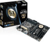
when the system hangs due to overclocking. For system failure due to overclocking, use the CPU Parameter Recall (C.P.R.) feature. Shut down and reboot the system, then the BIOS automatically resets parameter settings to default values. 2. RTC Battery header (2-pin BATT_CON) This connector is for - Asus H170-PRO/USB 3.1 | Motherboard Pin Definition.English - Page 4
to clear the RTC when the system hangs due to overclocking. For system failure due to overclocking, use the CPU Parameter Recall (C.P.R) feature. Shut down and reboot the system so the BIOS can automatically reset parameter settings to default values. 2. Intel® ME jumper (3-pin DIS_ME) This jumper - Asus H170-PRO/USB 3.1 | Motherboard Pin Definition.English - Page 5
to wake up the computer from S1 sleep mode (CPU stopped, DRAM refreshed, system running in low power USBPWF mode) using the connected ATX power supply that can supply at least 1A on the +5VSB lead, and a corresponding setting in the BIOS. 12 23 KB_USBPWB +5V +5VSB (Default) 5. Display panel - Asus H170-PRO/USB 3.1 | Motherboard Pin Definition.English - Page 6
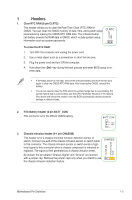
CHA FAN IN CHA FAN PWR GND Do not forget to connect the fan cables to the fan connectors. Insufficient air flow inside the system may damage the motherboard components. These are not jumpers! Do not place C jumper caps on the fan connectors! The CPU_FAN connector supports a CPU fan of maximum - Asus H170-PRO/USB 3.1 | Motherboard Pin Definition.English - Page 7
.asus. com/PowerSupplyCalculator/PSCalculator.aspx?SLanguage=en-us for details. 7. Speaker connector (4-pin SPEAKER) The 4-pin connector is for the chassis-mounted system warning speaker. The speaker allows you hear system beeps and warnings. SPEAKER +5V GND GND Speaker Out PIN 1 Motherboard - Asus H170-PRO/USB 3.1 | Motherboard Pin Definition.English - Page 8
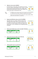
the back of the system chassis. +5V SPDIFOUT GND 10. Direct connector (2-pin DRCT) This connector is for the chassis-mounted button that supports the DirectKey function. Connect the button cable that supports DirectKey, from the chassis to this connector on the motherboard. DRCT DRCT GND Ensure - Asus H170-PRO/USB 3.1 | Motherboard Pin Definition.English - Page 9
in the BIOS setup if the Intel® chipset. The SATAEXPRESS connector can support one SATA Express device or two SATA devices. GND RSATA_TXP1 RSATA_TXN1 GND RSATA_RXN1 RSATA_RXP1 GND GND RSATA_TXP2 RSATA_TXN2 GND RSATA_RXN2 RSATA_RXP2 GND Floating Device_Reset GND Detection SATAEXPRESS Motherboard - Asus H170-PRO/USB 3.1 | Motherboard Pin Definition.English - Page 10
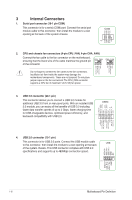
• Reset button (2-pin RESET) This 2-pin connector is for the chassis-mounted reset button for system reboot without turning off the system power. System panel connector (20-8 pin PANEL) This connector supports several chassis-mounted functions. • System power LED (2-pin PWR_LED) F_PANEL +PWR_LED - Asus H170-PRO/USB 3.1 | Motherboard Pin Definition.English - Page 11
System panel connector (20-5 pin PANEL) This connector supports several chassis-mounted functions. • System power LED (4-pin +PWR_LED-) PANEL +PWR_LED- PWR_SW SPEAKER PLED+ PLEDPWR Ground +5V_SPKO Ground Ground Speaker This 2-pin connector is for the system power LED. Connect the chassis power - Asus H170-PRO/USB 3.1 | Motherboard Pin Definition.English - Page 12
System panel connector (20-3 pin F_PANEL) This connector supports several chassis-mounted functions. • System power LED (4-pin +PWR_LED-) PANEL +PWR_LED- PWR_SW SPEAKER PLED+ PLEDPWR GND +5V GND GND Speaker Intruder# This 2-pin connector is for the system power LED. Connect the chassis power - Asus H170-PRO/USB 3.1 | Motherboard Pin Definition.English - Page 13
connector (14-1 pin TPM) PWRDWN F_SERIRQ F_FRAME# F_LAD3 F_LAD2 F_LAD1 F_LAD0 This connector supports a Trusted Platform Module (TPM) system This socket supports M Key and 2242/2260/2280/22110 or 2242/2260/22110 storage devices by models. • When using Intel® Desktop Motherboard Pin Definition 1-13 - Asus H170-PRO/USB 3.1 | Motherboard Pin Definition.English - Page 14
this connector in only one orientation. Find the proper orientation and push down firmly until the connector completely fits. ATX19V GND PIN 1 DC_JACK_IN This connector supports 12V and 19V by models. Refer to the specification sheet of the model for details. 1-14 Motherboard Pin Definition - Asus H170-PRO/USB 3.1 | Motherboard Pin Definition.English - Page 15
GND DMIC_CLK PIN 1 26. Custom header (14-pin CUSTOM) The custom header is for connecting customized modules for additional features. CUSTOM PIN 1 Prog_LED +3.3 VSB PWRBT# +5 VSB USB+ SCI/SMI GPIO Ground SMB_SLK SMB_Data HDMI CEC No Connection USBWDTO#/GPIO Motherboard Pin Definition 1-15 - Asus H170-PRO/USB 3.1 | Motherboard Pin Definition.English - Page 16
when the KeyBot button is pressed. 5. USB BIOS Flashback LED (FLBK_LED) This LED flashes when you press the BIOS Flashback button for BIOS update. 6. Q-Code LED (Q_CODE) The Q-Code LED design provides you with a 2-digit error code that displays the system status. 1-16 Motherboard Pin Definition - Asus H170-PRO/USB 3.1 | Motherboard Pin Definition.English - Page 17
and load the BIOS default settings. A message will appear during POST reminding you that the BIOS has been restored to its default settings. • We recommend that you download and update to the latest BIOS version from the ASUS website at www.asus.com after using the MemOK! function. Motherboard Pin - Asus H170-PRO/USB 3.1 | Motherboard Pin Definition.English - Page 18
CMOS button (CLR_CMOS) Press this button to clear the BIOS setup information only when the systems hangs due to overclocking. 5. KeyBot button (KeyBot) Press this button to activate the KeyBot feature. The KeyBot feature supports USB keyboards only. KEBOT 6. Sonic SoundStage button (SOUNDSTAGE
-
 1
1 -
 2
2 -
 3
3 -
 4
4 -
 5
5 -
 6
6 -
 7
7 -
8
-
9
-
10
-
11
-
12
-
13
-
14
-
15
-
16
-
17
-
18
 |
 |

Motherboard Pin
Definition
1
E11133
Revised Edition v2
December 2015