Asus K8N-LR User Manual
Asus K8N-LR Manual
 |
View all Asus K8N-LR manuals
Add to My Manuals
Save this manual to your list of manuals |
Asus K8N-LR manual content summary:
- Asus K8N-LR | User Manual - Page 1
K8N-LR Motherboard - Asus K8N-LR | User Manual - Page 2
express written permission of ASUSTeK COMPUTER INC. ("ASUS"). Product warranty or service will not be extended if: (1) the ASUS HAS BEEN ADVISED OF THE POSSIBILITY OF SUCH DAMAGES ARISING FROM ANY DEFECT OR ERROR IN THIS MANUAL OR PRODUCT. SPECIFICATIONS AND INFORMATION CONTAINED IN THIS MANUAL - Asus K8N-LR | User Manual - Page 3
x K8N-LR specifications summary xi Chapter 1: Product introduction 1.1 Welcome 1-1 1.2 Package contents 1-1 1.3 Special features 1-2 1.3.1 Product highlights 1-2 1.3.2 Innovative ASUS features 1-4 Chapter 2: Hardware information 2.1 Before you proceed 2-1 Onboard LEDs 2-1 2.2 Motherboard - Asus K8N-LR | User Manual - Page 4
utility 4-2 4.1.3 ASUS CrashFree BIOS 2 utility 4-5 4.1.4 ASUS Update utility 4-7 4.2 BIOS setup program 4-10 4.2.1 BIOS menu screen 4-11 4.2.2 Menu bar 4-11 4.2.3 Navigation keys 4-11 4.2.4 Menu items 4-12 4.2.5 Sub-menu items 4-12 4.2.6 Configuration fields 4-12 4.2.7 Pop-up window 4-12 - Asus K8N-LR | User Manual - Page 5
the BIOS RAID items 5-3 5.2.2 Entering the NVIDIA® RAID Utility 5-4 5.2.3 Creating a RAID 0 set (Stripe 5-5 5.2.4 Creating a RAID 1 set (Mirror 5-7 5.2.5 Rebuilding a RAID set 5-8 5.2.6 Deleting a RAID array 5-9 5.2.7 Clearing the disk data 5-10 Chapter 6: Driver installation 6.1 RAID driver - Asus K8N-LR | User Manual - Page 6
Contents 6.2 LAN driver installation 6-3 6.3 Support CD information 6-4 6.3.1 Running the support CD 6-4 6.3.2 Drivers menu 6-5 6.3.3 Management Software 6-6 6.3.4 Utilities 6-7 Appendix: Reference information A.1 K8N-LR block diagram A-1 vi - Asus K8N-LR | User Manual - Page 7
and, if not installed and used in accordance with manufacturerʼs instructions, may cause harmful interference to radio communications. However, there is reception, which can be determined by turning the equipment off and on, the user is encouraged to try to correct the interference by one or more of - Asus K8N-LR | User Manual - Page 8
service technician or your retailer. Operation safety • Before installing the motherboard and adding devices on it, carefully read all the manuals and staples away from connectors, slots, sockets and circuitry. • Avoid dust, technical problems with the product, contact a qualified service technician - Asus K8N-LR | User Manual - Page 9
descriptions of the BIOS parameters are also provided. • Chapter 5: RAID configuration Provides information on RAID configurations for this motherboard. • Chapter 6: Driver installation This chapter provides information on RAID and LAN driver installation for this motherboard. • Appendix: Reference - Asus K8N-LR | User Manual - Page 10
of the following symbols used throughout this manual. DANGER/WARNING: Information to prevent injury to yourself when trying to complete a task. CAUTION: Information to prevent damage to the components when trying to complete a task. IMPORTANT: Instructions that you MUST follow to complete a task - Asus K8N-LR | User Manual - Page 11
K8N-LR specifications summary CPU Chipset System Bus Memory Expansion slots Storage Dual LAN USB Special features Rear panel BIOS features Power Requirement Socket 939 for AMD Athlon™ 64 and Opteron™ 64 processors Supports AMD 64 architecture that enables simultaneous 32-bit and 64-bit computing - Asus K8N-LR | User Manual - Page 12
K8N-LR specifications summary Internal connectors Form Factor Support CD contents 1 x Floppy disk drive connector 2 x IDE connectors 4 x Serial ATA connectors 2 x CPU panel connector ATX form factor: 12 in x 9.6 in (30.5 cm x 24.4 cm) Device drivers ASUS Live Update utility NVIDIA Raid Utility * - Asus K8N-LR | User Manual - Page 13
This chapter describes the motherboard features and the new technologies it supports. 1Product introduction - Asus K8N-LR | User Manual - Page 14
Chapter summary 1.1 Welcome 1-1 1.2 Package contents 1-1 1.3 Special features 1-2 ASUS K8N-LR - Asus K8N-LR | User Manual - Page 15
Package contents Check your motherboard package for the following items. Motherboard ASUS K8N-LR motherboard Cables 1 x Serial ATA cable 1 x USB 2.0 cable 1 x 3-in-1 IDE cable Accessories I/O shield Application CD ASUS motherboard support CD Documentation User guide If any of the above - Asus K8N-LR | User Manual - Page 16
. See page 2-14 and 2-15 for details. Dual Channel DDR memory support Employing the Double Data Rate (DDR) memory technology, the motherboard supports up to 4GB of system memory using DDR400/333/266 DIMMs. The ultra-fast 400MHz memory bus delivers the required bandwidth for the latest 3D graphics - Asus K8N-LR | User Manual - Page 17
the support CD in case when the BIOS codes and data are corrupted. This protection eliminates the need to buy a replacement ROM chip. See details on page 4-5. ASUS MyLogo2™ This new feature present in the motherboard allows you to personalize and add style to your system with customizable boot logos - Asus K8N-LR | User Manual - Page 18
1-4 Chapter 1: Product introduction - Asus K8N-LR | User Manual - Page 19
This chapter lists the hardware setup procedures that you have to perform when installing system components. It includes description of the jumpers and connectors on the motherboard. 2 Hardware information - Asus K8N-LR | User Manual - Page 20
Chapter summary 2.1 Before you proceed 2-1 2.2 Motherboard overview 2-2 2.3 Central Processing Unit (CPU 2-6 2.4 System memory 2-11 2.5 Expansion slots 2-13 2.6 Jumpers 2-16 2.7 Connectors 2-20 ASUS K8N-LR - Asus K8N-LR | User Manual - Page 21
that a processor is not installed or the processor is not installed properly in CPU socket. SB_PWR1 R K8N-LR ON Standby Power OFF Powered Off CPU_WARN1 K8N-LR Standby Power LED ON No CPU installed No CPU on socket CPU CPU types mismatched OFF No detected CPU problem ASUS K8N-LR 2-1 - Asus K8N-LR | User Manual - Page 22
the image below. 2.2.2 Screw holes Place nine (9) screws into the holes indicated by circles to secure the motherboard to the chassis. Do not overtighten the screws! Doing so can damage the motherboard. Place this side towards the rear of the chassis R K8N-LR 2-2 Chapter 2: Hardware information - Asus K8N-LR | User Manual - Page 23
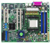
,184-pin module) DDR DIMM_B1 (64 bit,184-pin module) SOCKET 939 ATXPWR1 CPU_FAN2 CPU_FAN1 8Mb Flash J1 FRNT_FAN2 PARALLEL PORT VGA1 LAN1 SATA1 SATA2 SATA4 SATA3 LAN2 LAN_EN1 Gigabit LAN PCIE1 R PCIX1 K8N-LR Gigabit LAN LAN_EN2 ATI RAGE XL REAR_FAN1 VGA_EN1 COM2 PCIX2 CR2032 3V Lithium - Asus K8N-LR | User Manual - Page 24
Slots/Sockets 1. CPU sockets 2. DDR DIMM sockets 3. PCI Express x16 slot 4. PCI/PCI-X slotos Jumpers 1. Clear RTC RAM (3-pin CLRTC) 2. Keyboard power (3-pin KBPWR1) 3. VGA graphics controller setting (3-pin VGA_EN1) 4. Gigabit LAN controller setting (3-pin LAN_EN1, LAN_EN2) 5. Force BIOS recovery - Asus K8N-LR | User Manual - Page 25
Serial ATA connectors (7-pin SATA1, SATA2, SATA3, SATA4) 4. CPU, Front, and Rear Fan connectors (3-pin CPU_FAN1/2, FRONT_FAN1/2, REAR_FAN1 , USB78, USB910) 7. Serial port connector (10-1 pin COM2) 8. ATX power connectors (24-pin ATXPWR1, 4-pin ATX12V) 9. Power supply SMBus 2-27 2-28 ASUS K8N-LR 2-5 - Asus K8N-LR | User Manual - Page 26
to ensure correct installation. Notched corner 2.3.2 Installing the CPU To install a CPU: 1. Locate the CPU socket on the motherboard. R K8N-LR K8N-LR CPU Socket 939 Gold Arrow Before installing the CPU, make sure that the socket box is facing towards you and the load lever is on your left - Asus K8N-LR | User Manual - Page 27
corner The CPU fits only in one correct orientation. DO NOT force the CPU into the socket to prevent bending the pins and damaging the CPU! 5. When the CPU is in place, push down the socket lever to secure the CPU. The lever clicks on the side tab to indicate that it is locked. ASUS K8N-LR 2-7 - Asus K8N-LR | User Manual - Page 28
• The retention module base is already installed on the motherboard upon purchase. • You do not have to remove the retention module base when installing the CPU or installing other motherboard components. • If you purchased a separate CPU heatsink and fan assembly, make sure that a Thermal Interface - Asus K8N-LR | User Manual - Page 29
the retention bracket in place. 4. Push down the retention bracket lock on the retention mechanism to secure the heatsink and fan to the module base. ASUS K8N-LR 2-9 - Asus K8N-LR | User Manual - Page 30
fan cable to the appropriate connector on the motherboard, CPU_FAN1 or CPU_FAN2. CPU_FAN2 CPU_FAN2 GND +12V Rotation R K8N-LR CPU_FAN1 CPU_FAN1 Rot+a1ti2oVn GND K8N-LR CPU Fan Connectors Do not forget to connect the CPU fan connector! Hardware monitoring errors can occur if you fail to plug - Asus K8N-LR | User Manual - Page 31
System memory 2.4.1 Overview The motherboard comes with four 184-pin Double Data Rate (DDR) Dual Inline Memory Modules (DIMM) sockets. The following figure illustrates the location of the sockets: 104 Pins 80 Pins R K8N-LR DIMM_A2 DIMM_A1 DIMM_B2 DIMM_B1 K8N-LR 184-pin DDR DIMM Sockets Channel - Asus K8N-LR | User Manual - Page 32
before adding or removing DIMMs or other system components. Failure to do so may cause severe damage to both the motherboard and the components. 1. Unlock a DIMM socket by pressing the retaining clips outward. 2. Align a DIMM on the socket such that the notch on the DIMM matches the break on the - Asus K8N-LR | User Manual - Page 33
cards that they support. Make sure to unit cover (if your motherboard is already installed in a BIOS settings, if any. See Chapter 4 for information on BIOS setup. 2. Assign an IRQ to the card. Refer to the tables on the next page. 3. Install the software drivers for the expansion card. ASUS K8N-LR - Asus K8N-LR | User Manual - Page 34
Processor Primary IDE Channel Secondary IDE Channel * These IRQs are usually available for ISA or PCI devices. 2.5.4 PCI Express x16 slot This motherboard supports PCI Express x16 graphic cards that comply with the PCI Express specifications. The figure shows a graphics card installed on the PCI - Asus K8N-LR | User Manual - Page 35
PCI/PCI-X slots support cards such as a LAN card, USB card, and other cards that comply with PCI 2.3 and PCI-X 1.0 specifications. The figure shows a LAN card installed on a 32-bit PCI slot and a RAID card on a PCI-X 2 slot (PCIX2) -populated populated Frequency 133MHz 133MHz 100MHz ASUS K8N-LR 2-15 - Asus K8N-LR | User Manual - Page 36
can clear the CMOS memory of date, time, and boot process and enter BIOS setup to re-enter data. Except when clearing the RTC RAM, never remove the cap on CLRTC jumper default position. Removing the cap will cause system boot failure! R K8N-LR CLRTC1 12 23 Normal (Default) Clear CMOS K8N-LR - Asus K8N-LR | User Manual - Page 37
(the default is the Space Bar). This feature requires an ATX power supply that can supply at least 1A on the +5VSB lead, and a corresponding setting in the BIOS. R K8N-LR KBPWR1 12 23 +5V (Default) +5VSB K8N-LR Keyboard Power Setting 3. VGA Graphics controller setting (3-pin VGA_EN1) These - Asus K8N-LR | User Manual - Page 38
onboard Broadcom® BCM5721 Gigabit LAN controllers. The LAN_EN1 jumper controls the LAN1 port. The LAN_EN2 iumper controls the LAN2 port. R K8N-LR LAN_EN1 12 23 Enable (Default) Disable K8N-LR LAN_EN1 Setting R K8N-LR LAN_EN2 12 23 Enable (Default) Disable K8N-LR LAN_EN2 Setting 2-18 - Asus K8N-LR | User Manual - Page 39
down your computer. 7. Replace the jumper cap from pins 1-2 to pins 2-3. 8. Reboot your computer. 9. Hold down the key during the boot process and enter BIOS setup to re-enter data. R K8N-LR RECOVERY1 12 23 BIOS recovery Normal (Default) K8N-LR BIOS Recovery Setting ASUS K8N-LR 2-19 - Asus K8N-LR | User Manual - Page 40
to a Local Area Network (LAN) through a network hub. Refer to the table below for the LAN port LED indications. 4. LAN1 (RJ-45) port. Supported by the BROADCOM® BCM5721 Gigabit LAN controller, this port allows Gigabit connection to a Local Area Network (LAN) through a network hub. Refer to the - Asus K8N-LR | User Manual - Page 41
to PIN 1. 1 K8N-LR Floppy Disk Drive Connector 2. IDE connectors (40-1 pin PRI_IDE1, SEC_IDE1) These connectors are for Ultra DMA 133/100/66/33 signal cables. The Ultra DMA 133/100/66/33 signal cable has three connectors: a blue connector for the primary IDE connector on the motherboard, a black - Asus K8N-LR | User Manual - Page 42
ATA hard disk drives, you can create a RAID 0, RAID 1, RAID 0+1, JBOD, or RAID 5 configuration. SATA2 GND RSATA_TXP2 RSATA_TXN2 GND RSATA_RXN2 RSATA_RXP2 GND SATA1 GND RSATA_TXP2 RSATA_TXN2 GND RSATA_RXN2 RSATA_RXP2 GND R K8N-LR SATA4 GND RSATA_TXP2 RSATA_TXN2 GND RSATA_RXN2 RSATA_RXP2 GND - Asus K8N-LR | User Manual - Page 43
Lack of sufficient air flow inside the system may damage the motherboard components. These are not jumpers! DO NOT place jumper caps on the fan connectors! • All fan features the ASUS Smart Fan technology. R K8N-LR CPU_FAN2 CPU_FAN1 FRNT_FAN2 FRNT_FAN1 CPU_FAN2 CPU_FAN1 Rotation +12V GND GND +12V - Asus K8N-LR | User Manual - Page 44
. These connectors comply with the USB 2.0 specification that supports up to 480 Mbps connection speed. USB34 USB78 USB+5V USB_P4USB_P4+ GND NC USB+5V USB_P4USB_P4+ GND NC USB+5V USB_P3USB_P3+ GND USB+5V USB_P3USB_P3+ GND R K8N-LR USB56 USB910 USB+5V USB_P3USB_P3+ GND USB+5V USB_P3USB_P3 - Asus K8N-LR | User Manual - Page 45
Find the proper orientation and push down firmly until the connectors completely fit. • Do not forget to connect the 4-pin ATX +12 V power plug; otherwise, the system will not boot +5 Volts +5 Volts Ground K8N-LR ATX Power Connectors For Power Supply with 20-pin Power Connector ASUS K8N-LR 2-25 - Asus K8N-LR | User Manual - Page 46
These connectors are for the ASUS server management cards. +5VSB +5VSB BMC SMBCLK 12CCLK1 PSON# BMC_RST# PWROK PSONEN# +5VSB +5VSB BMC SMBDATA 12CDATA1 FP_PWRBTN# BMC_PRESENT# BMC_SMI# GND R K8N-LR BMCCONN1 K8N-LR BMC Connector R K8N-LR BMCSOCKET1 K8N-LR BMCSOCKET Connector 2-26 Chapter - Asus K8N-LR | User Manual - Page 47
This connector supports several server system functions. AUX_PANEL1 NC I2CCLK_P2 GND I2CDATA_P2 +5VSB LAN1_LINKACTLED+ LAN1_LINKACTLEDLAN2_LINKACTLEDLAN2_LINKACTLED+ R K8N-LR +5VSB CASEOPEN communicate with an SMBus host and/or other SMBus devices using the SMBus interface. ASUS K8N-LR 2-27 - Asus K8N-LR | User Manual - Page 48
supports several chassis-mounted functions. R K8N-LR PANEL1 POWERLED+ GND POWERLEDMLED+ MLEDNC +5V GND GND SPKROUT HDLED+ HDLEDNMIBTN# GND POWERBTN# GND NC RESETBTN# GND K8N-LR System Panel Connector The system panel connector is color-coded system beeps and on the BIOS settings. Pressing - Asus K8N-LR | User Manual - Page 49
This chapter describes the power up Powerin3g up sequence, the POST messages, and ways of shutting down the system. - Asus K8N-LR | User Manual - Page 50
Chapter summary 3.1 Starting up for the first time 3-1 3.2 Powering off the computer 3-2 ASUS K8N-LR - Asus K8N-LR | User Manual - Page 51
lights up. For systems with ATX power supplies, the system LED lights up when you press the ATX power button. If your test or POST. While the tests are running, the BIOS beeps or additional messages appear on the screen. If you BIOS Setup. Follow the instructions in Chapter 4. ASUS K8N-LR 3-1 - Asus K8N-LR | User Manual - Page 52
the computer 3.2.1 Using the OS shut down function If you are using Windows® 2000/2003 Server: 1. Click the Start button then click Shut Down system to sleep mode or to soft-off mode, depending on the BIOS setting. Pressing the power switch for more than four seconds lets the system enter the soft- - Asus K8N-LR | User Manual - Page 53
This chapter tells how to change the system settings through the BIOS Setup menus. Detailed descriptions of the BIOS parameters are also provided. 4 BIOS setup - Asus K8N-LR | User Manual - Page 54
Chapter summary 4.1 Managing and updating your BIOS 4-1 4.2 BIOS setup program 4-10 4.3 Main menu 4-13 4.4 Advanced menu 4-18 4.5 Power menu 4-30 4.6 Boot menu 4-34 4.7 Exit menu 4-38 ASUS K8N-LR - Asus K8N-LR | User Manual - Page 55
System (BIOS) setup. 1. ASUS AFUDOS (Updates the BIOS in DOS mode using a bootable floppy disk.) 2. ASUS CrashFree BIOS 2 (Updates the BIOS using a bootable floppy disk or the motherboard support CD when the BIOS file fails or gets corrupted.) 3. ASUS Update (Updates the BIOS in Windows® environment - Asus K8N-LR | User Manual - Page 56
actual BIOS screen displays may not be same as shown. 1. Copy the AFUDOS utility (afudos.exe) from the motherboard support CD to the bootable floppy disk you created earlier. 2. Boot the system in DOS mode, then at the prompt type: afudos /o[filename] where the [filename] is any user-assigned filename - Asus K8N-LR | User Manual - Page 57
(afudos.exe) from the motherboard support CD to the bootable floppy disk you created earlier. 3. Boot the system in DOS mode, then at the prompt type: afudos /i[filename] where [filename] is the latest or the original BIOS file on the bootable floppy disk. A:\>afudos /iK8N-LR.ROM ASUS K8N-LR 4-3 - Asus K8N-LR | User Manual - Page 58
or reset the system while updating the BIOS to prevent system boot failure! 5. The utility returns to the DOS prompt after the BIOS update process is completed. Reboot the system from the hard disk drive. A:\>afudos /iK8N-LR.ROM /pbnc AMI Firmware Update Utility - Version 1.19(ASUS V2.07(03.11.24BB - Asus K8N-LR | User Manual - Page 59
disk that contains the updated BIOS file. • Prepare the motherboard support CD or the floppy disk containing the updated motherboard BIOS before using this utility. • Make sure that you rename the original or updated BIOS file in the floppy disk to K8N-LR.ROM. Recovering the BIOS from a floppy disk To - Asus K8N-LR | User Manual - Page 60
le "K8N-LR.ROM". Completed. Start flashing... DO NOT shut down or reset the system while updating the BIOS! Doing so can cause system boot failure! 4. Restart the system after the utility completes the updating process. The recovered BIOS may not be the latest BIOS version for this motherboard. Visit - Asus K8N-LR | User Manual - Page 61
ASUS Update: 1. Place the support CD in the optical drive. The Drivers menu appears. 2. Click the Utilities tab, then click Install ASUS Update VX.XX.XX. 3. The ASUS Update utility is copied to your system. Quit all Windows® applications before you update the BIOS using this utility. ASUS K8N-LR - Asus K8N-LR | User Manual - Page 62
the ASUS Update utility from the Windows® desktop by clicking Start > Programs > ASUS > ASUSUpdate > ASUSUpdate. The ASUS Update main window appears. 2. Select Update BIOS from the Internet option from the drop-down menu, then click Next. 3. Select the ASUS FTP site nearest you to avoid network - Asus K8N-LR | User Manual - Page 63
> ASUS > ASUSUpdate > ASUSUpdate. The ASUS Update main window appears. 2. Select Update BIOS from a file option from the drop-down menu, then click Next. 3. Locate the BIOS file from the Open window, then click Save. 4. Follow the screen instructions to complete the update process. ASUS K8N-LR 4-9 - Asus K8N-LR | User Manual - Page 64
setup program This motherboard supports a programmable firmware chip that you can update using the provided utility described in section "4.1 Managing and updating your BIOS." Use the BIOS Setup program when you are installing a motherboard, reconfiguring your system, or prompted to "Run Setup". This - Asus K8N-LR | User Manual - Page 65
4.2.1 BIOS menu screen Menu items Menu bar Configuration For changing the advanced power management (APM) configuration For changing the system boot configuration For selecting the exit options and loading default settings To select an item differ from one screen to another. ASUS K8N-LR 4-11 - Asus K8N-LR | User Manual - Page 66
(Advanced, Power, Boot, and Exit) on 3.5 in] [English] :[ST320413A] :[ASUS CD-S340] :[Not Detected] :[Not select an item that is not user-configurable. A configurable window." 4.2.7 Pop-up window Select a menu item then press to display a pop-up window Memory up window Scroll bar At the - Asus K8N-LR | User Manual - Page 67
screen appears, giving you an overview of the basic system information. Refer to section "4.2.1 BIOS menu screen" for information on the menu screen items and how to navigate through them. ] [360K, 5.25 in.] [1.2M , 5.25 in.] [720K , 3.5 in.] [1.44M, 3.5 in.] [2.88M, 3.5 in.] ASUS K8N-LR 4-13 - Asus K8N-LR | User Manual - Page 68
DMA-2 Ultra DMA : Ultra DMA-5 SMART Monitoring: Supported Type [Auto] LBA/Large Mode [Auto] Block(Multi-Sector Transfer) [Auto] PIO Mode [Auto] DMA Mode [Auto] SMART Monitoring [Auto] 32Bit Data Transfer [Disabled] The BIOS automatically detects the values opposite the dimmed items - Asus K8N-LR | User Manual - Page 69
Protect IDE Dectect Time Out (Sec) ATA(PI) 80Pin Cable Detection First Boot Device from Configuration nVidia RAID ROM [Both] [Enabled] [Enabled] [Disabled] [35] [Host] [P- This will be effective only if device is accessed through BIOS. Configuration options: [Disabled] [Enabled] ASUS K8N-LR 4-15 - Asus K8N-LR | User Manual - Page 70
[Host & Device] [Host] [Device] First Boot Device from [P-ATA] Selects the First Boot Device. Configuration options: [P-ATA] [S-ATA] Configuration nVidia RAID ROM Configuration nVidia RAID ROM RAID Option ROM [Disabled] Disable/Enable nVidia ROM. RAID Option ROM [Disabled] Enables or disables the - Asus K8N-LR | User Manual - Page 71
: 01/06/06 Processor Type Speed Count : AMD Opteron(tm) Processor 146 : 2000 MHz : 1 System Memory Size : 256MB AMI BIOS Displays the auto-detected BIOS information Processor Displays the auto-detected CPU specification System Memory Displays the auto-detected system memory ASUS K8N-LR 4-17 - Asus K8N-LR | User Manual - Page 72
and Exit ESC Exit 4.4.1 CPU Configuration The items in this menu show the CPU-related information that the BIOS automatically detects. CPU Configuration Module Version: This option should remain disabled for the normal operation. The driver developer may enable it for testing purpose. GART Error - Asus K8N-LR | User Manual - Page 73
Continuous] Sets the method used for programming CPU MTRRs when 4GB or more memory is installed on the system. When set to Discrete, the BIOS leaves the PCI hole below the 4GB boundary ns : 7 ns Select Screen Select Item +- Change Option F1 General Help F10 Save and Exit ESC Exit ASUS K8N-LR 4-19 - Asus K8N-LR | User Manual - Page 74
memory settings. Memory Configuration Memclock Mode CMD-ADDR Timing Mode Burst Length HardtWare Memory Hole [Auto] [ 1T] [4 Beats] [Disabled] MEMCLK can be set by the code Memclock Value [100 MHz] Sets the memory clock mode limit. This item appears only when the Memory Mode item is set to Limit. - Asus K8N-LR | User Manual - Page 75
] [Disabled] [Disabled] [Disabled] DRAM ECC allows hardware to report and correct memory errors automatically maintaining system integrity. Select Screen Select Item DRAM ECC Enable [Enabled] .7us] [655.4us] [1.31ms] [2.62ms] [5.24ms] [10.49ms] [20.97ms] [42.00ms] [84.00ms] ASUS K8N-LR 4-21 - Asus K8N-LR | User Manual - Page 76
Chipset Configuration SMBus Interface [Enabled] IOAPIC [Enabled] CPU Spread Spectrum [Disabled] SATA Spread Spectrum [Disabled] PCI or disable the IO APIC. Configuration options: [Enabled] [Disabled] CPU Spread Spectrum [Disabled] Sets or disables the processor spread spectrum. Configuration - Asus K8N-LR | User Manual - Page 77
Port Mode Parallel Port IRQ Onboard BCM5721 Lan Onboard LAN Boot ROM [3F8/IRQ4] [2F8/IRQ3] [Normal] [378] [Normal] [IRQ7] [Enabled] [Disabled] Allows BIOS to Select Serial Port1 Base Addresses. Serial Serial Port2 (IR Mode). Configuration options: [Half Duplex] [Full Duplex] ASUS K8N-LR 4-23 - Asus K8N-LR | User Manual - Page 78
IRQ [IRQ7] Allows you to set the Parallel Port IRQ. Configuration options: [IRQ5] [IRQ7] Onboard BCM5721 LAN [Enabled] Enable or disable the Onboard BCM5721 LAN. Configuration options: [Disabled] [Enabled] Onboard LAN Boot ROM [Disabled] Allows you to enable or disable the option ROM in the onboard - Asus K8N-LR | User Manual - Page 79
or legacy ISA devices, and setting the memory size block for legacy ISA devices. Take And Play O/S [No] When set to [No], BIOS configures all the devices in the system. When set configures the Plug and Play devices not required for boot. Configuration options: [No] [Yes] PCI Latency ASUS K8N-LR 4-25 - Asus K8N-LR | User Manual - Page 80
and parameters Remote Access [Enabled] Serial port number Base Address Serial Port Mode Flow Control Redirection After BIOS POST Terminal Type VT-UTFB Combo Key Support Media Type [COM1] [3F8h, 4] [115200 8,n,1] [None] [Always] [ANSI] [Enabled] [Serial] Select Remote Access type. Remote Access - Asus K8N-LR | User Manual - Page 81
[VT-UTF8] VT-UTF8 Combo Key Support [Enabled] Enables or disables the VT-UTF8 combo key support for ANSI or VT100 terminals. Configuration options: [Disabled] [Enabled] Media Type [Serial] Selects the media for console redirection. Configuration options: [Serial] [LAN] [Serial+LAN] ASUS K8N-LR 4-27 - Asus K8N-LR | User Manual - Page 82
display the configuration options. USB Configuration Module Version - 2.24.0-F.4 USB Devices Enabled: None USB Controller Support Legacy USB Support USB 2.0 Controller Mode BIOS EHCI Hand-Off [USB 1.1+USB 2.0] [Enabled] [HiSpeed] [Enabled] Enables USB host controllers. The Module Version and USB - Asus K8N-LR | User Manual - Page 83
capable. CPU HT Link Speed [Auto] Allows you to set the Hyper Transport Link speed. Configuration options: [Auto] [200 MHz] [400 MHz] [600 MHz] [800 MHz] [1 GHz] CPU HT Link Width [Auto] Allows you to set the Hyper Transport Link width. Configuration options: [Auto][8 Bit] [16 Bit] ASUS K8N-LR 4-29 - Asus K8N-LR | User Manual - Page 84
] [Enabled] Do not change the ACPI APIC support after you have installed the operating system (OS), otherwise, a boot failure may occur. 4.5.3 ACPI MCFG Support [Enabled] Allows you to enable or disable the Memory Mapped Configuration (MCFG) support. When set to Enabled, the MCFG table pointer - Asus K8N-LR | User Manual - Page 85
the system after AC power loss. Power Management/APM [Enabled] Allows you to enable or disable the motherboard Advance Power Management (APM) feature. Configuration options: [Enabled] [Disabled] Power Button Mode [On/ is in Soft-off mode. Configuration options: [Disabled] [Enabled] ASUS K8N-LR 4-31 - Asus K8N-LR | User Manual - Page 86
[Enabled], this parameter allows you to use the PS/2 mouse to turn on the system. This feature requires an ATX power supply that provides at least 1A on the +5VSB lead. Configuration options: [Disabled] [Enabled] RTC guration options: [Power Off] [Power On] [Last State] 4-32 Chapter 4: BIOS setup - Asus K8N-LR | User Manual - Page 87
the motherboard and CPU temperatures. Select [Ignored] if you do not wish to display the detected temperatures. CPU Fan1/Fan2 CPU Target Temperature [XXX] MB Target Temperature [XXX] Allows you to set the CPU and system threshold temperature before the Smart Fan Control is disabled. ASUS K8N-LR - Asus K8N-LR | User Manual - Page 88
Boot menu The Boot menu items allow you to change the system boot Boot Device Priority Boot Device Priority 1st Boot Device 2nd Boot Device 3rd Boot Device [1st FLOPPY DRIVE] [PM-ST330620A] [PS-ASUS CD-S360] Specifies the boot xxth Boot Device [1st Floppy Drive] These items specify the boot device - Asus K8N-LR | User Manual - Page 89
Support Wait For 'F1' If Error Hit 'DEL' Message Display Interrupt 19 Capture [Enabled] [Disabled] [On] [Auto] [Enabled] [Enabled] [Disabled] Allows BIOS to skip certain tests while booting. This will decrease the time needed to boot 19. Configuration options: [Disabled] [Enabled] ASUS K8N-LR 4-35 - Asus K8N-LR | User Manual - Page 90
the supervisor password, follow the same steps as in setting a user password. To clear the supervisor password, select the Change Supervisor Password press . The message "Password Uninstalled" appears. If you forget your BIOS password, you can clear it by erasing the CMOS Real Time Clock (RTC - Asus K8N-LR | User Manual - Page 91
BIOS SETUP UTILITY Boot Security Settings Supervisor Password : Not Installed User Password : Not Installed Change Supervisor Password User Access Level Change User Password Clear User . To change the user password, follow the same steps as in setting a user password. ASUS K8N-LR 4-37 - Asus K8N-LR | User Manual - Page 92
user password. Password Check [Setup] When set to [Setup], BIOS checks for user password when accessing the Setup utility. When set to [Always], BIOS checks for user password both when accessing Setup and booting you select this option, a confirmation window appears. Select Ok to save the changes and - Asus K8N-LR | User Manual - Page 93
to fields other than System Date, System Time, and Password, the BIOS asks for a confirmation before exiting. Discard Changes Allows you to window appears. Select Ok to load default values. Select Exit & Save Changes or make other changes before saving the values to the non-volatile RAM. ASUS K8N-LR - Asus K8N-LR | User Manual - Page 94
4-40 Chapter 4: BIOS setup - Asus K8N-LR | User Manual - Page 95
This chapter provides instructions for setting up, creating, and configuring RAID sets using the available utilities. 5RAID configuration - Asus K8N-LR | User Manual - Page 96
Chapter summary 5.1 Setting up RAID 5-1 5.2 NVIDIA® RAID configurations 5-3 ASUS K8N-LR - Asus K8N-LR | User Manual - Page 97
disk drives for this setup. If you want to boot the system from a hard disk drive included in a created RAID set, copy first the RAID driver from the support CD to a floppy disk before you install an operating system to the selected hard disk drive. Refer to Chapter 6 for details. ASUS K8N-LR 5-1 - Asus K8N-LR | User Manual - Page 98
SATA hard disks for RAID configuration: 1. Install the SATA hard disks into the drive bays following the instructions in the system user guide. 2. Connect a SATA signal cable to the signal connector at the back of each drive and to the SATA connector on the motherboard. 3. Connect a SATA power cable - Asus K8N-LR | User Manual - Page 99
want to set as RAID. 5. Save your changes, then exit the BIOS Setup. • Refer to Chapter 4 for details on entering and navigating through the BIOS Setup. • The RAID BIOS setup screens shown in this section are for reference only, and may not exactly match the items on your screen. ASUS K8N-LR 5-3 - Asus K8N-LR | User Manual - Page 100
Restart the computer. 2. During POST, press to display the utility main menu. NVIDIA RAID Utility Oct 5 2004 - Define a New Array - RAID Mode: Striping Striping Block: Optimal Free Disks Loc Disk Model Name Array Disks Loc Disk Model Name 1.0.M XXXXXXXXXXXXXXXXXX 1.1.M XXXXXXXXXXXXXXXXXX - Asus K8N-LR | User Manual - Page 101
array block size. For multimedia computer systems used mainly for audio and video editing, we recommend a higher array block size Highlight the hard disk drives that you want to add in the RAID set, then press the right arrow key to select. The selected [↑↓] Select [ENTER] Popup ASUS K8N-LR 5-5 - Asus K8N-LR | User Manual - Page 102
RAID 0 set. A pop-up window appears. Clear disk data? [Y] YES [N] Cancel 8. Press to delete all data from the hard disk drives, or to continue creating the RAID RAID 0 set. Press to save your settings and exit the utility. NVIDIA RAID Utility Oct 5 2004 - Array List - Boot - Asus K8N-LR | User Manual - Page 103
the RAID 1 set. A pop-up window appears. RAID set. Press to backup exisitng data to a target hard disk drive. You will lose all data on the drives if you clear the disk data! 9. The utility displays the created RAID 1 set. Press to save your settings and exit the utility.0 ASUS K8N-LR - Asus K8N-LR | User Manual - Page 104
set: 1. From the Array List, use the up or down arrow keys to select the RAID set you want to rebuild, then press . The RAID set details appear. NVIDIA RAID Utility Oct 5 2004 - Array List - Boot No No Id Status 4 Healthy 3 Healthy Vendor NVIDIA NVIDIA Array Model Name STRIPING XXX.XXG - Asus K8N-LR | User Manual - Page 105
You will lose all data on the drives if you delete a disk array! 4. The Define a New Array menu appears when you press . Create a new RAID set following the instructions in the previous sections.. ASUS K8N-LR 5-9 - Asus K8N-LR | User Manual - Page 106
the disk data: 1. From the Array List, use the up or down arrow keys to select a RAID set, then press . The RAID set details appear. NVIDIA RAID Utility Oct 5 2004 - Array List - Boot No No Id Status 4 Healthy 3 Healthy Vendor NVIDIA NVIDIA Array Model Name STRIPING XXX.XXG MIRRORING XXX - Asus K8N-LR | User Manual - Page 107
This chapter provides instructions for installing the necessary drivers for different system components. 6Driver installation - Asus K8N-LR | User Manual - Page 108
Chapter summary 6.1 RAID driver installation 6-1 6.2 LAN driver installation 6-3 6.3 Support CD information 6-4 ASUS K8N-LR - Asus K8N-LR | User Manual - Page 109
application in the support CD) or in Windows® environment. To create a RAID driver disk in DOS: 1. Place the motherboard support CD in the optical drive. 2. Restart the computer, then enter the BIOS Setup. 3. Select the optical drive as the first boot priority to boot from the support CD. Save your - Asus K8N-LR | User Manual - Page 110
virus infection. To create a RAID driver disk in Windows®: 1. Place the motherboard support CD in the optical drive. 2. When the Drivers menu appears, click NVIDIA nForce(TM) SATARAID Driver to create an NVIDIA nForce SATA RAID driver disk. To install the RAID driver: 1. Install an operating system - Asus K8N-LR | User Manual - Page 111
the support CD to locate the file ASSETUP.EXE from the BIN folder. Double-click the ASSETUP.EXE to run the CD. 3. Click the Broadcom 5721 Driver option to begin installation. 4. Click Next when the InstallShield Wizard window appears. Follow screen instructions to continue installation. ASUS K8N-LR - Asus K8N-LR | User Manual - Page 112
without notice. Visit the ASUS website (www.asus.com) for updates. 6.3.1 Running the support CD Place the support CD to the optical drive. The CD automatically displays the Drivers menu if Autorun is enabled in your computer. Click an icon to display support CD/motherboard information Click an item - Asus K8N-LR | User Manual - Page 113
Rage XL Display Driver appears only under Windows® 2000 OS. Broadcom 5721 Driver Installs the Broadcom 5721 driver.See page 6-3 for details. Broadcom 5721 NetXtreme Software Utility Installs the Broadcom NetXtreme software application. Refer to the application help file for details. ASUS K8N-LR 6-5 - Asus K8N-LR | User Manual - Page 114
The Management Software menu shows the available server management software applications. Install ASUS Network Utility Installs the ASUS Network Utility. Refer to the application help file for details. ASWM Installs the ASWM (ASUS Server Web-based Managment). Refer to the application help file for - Asus K8N-LR | User Manual - Page 115
® DirectX 9.0c driver. The Microsoft DirectX ASUS screen saver. ASUS Update The ASUS Update utility that allows you to update the motherboard BIOS in Windows® environment. This utility requires an Internet connection either through a network or an Internet Service Provider (ISP). ASUS K8N-LR - Asus K8N-LR | User Manual - Page 116
6-8 Chapter 6: Driver installation - Asus K8N-LR | User Manual - Page 117
This appendix includes additional information that you may refer to when configuring the motherboard. Reference A information - Asus K8N-LR | User Manual - Page 118
Appendix summary A.1 K8N-LR block diagram A-1 ASUS K8N-LR - Asus K8N-LR | User Manual - Page 119
A.1 K8N-LR block diagram ASUS K8N-LR A-1 - Asus K8N-LR | User Manual - Page 120
A-2 Appendix A: Reference information
-
 1
1 -
 2
2 -
 3
3 -
 4
4 -
 5
5 -
 6
6 -
 7
7 -
8
-
9
-
10
-
11
-
12
-
13
-
14
-
15
-
16
-
17
-
18
-
19
-
20
-
21
-
22
-
23
-
24
-
25
-
26
-
27
-
28
-
29
-
30
-
31
-
32
-
33
-
34
-
35
-
36
-
37
-
38
-
39
-
40
-
41
-
42
-
43
-
44
-
45
-
46
-
47
-
48
-
49
-
50
-
51
-
52
-
53
-
54
-
55
-
56
-
57
-
58
-
59
-
60
-
61
-
62
-
63
-
64
-
65
-
66
-
67
-
68
-
69
-
70
-
71
-
72
-
73
-
74
-
75
-
76
-
77
-
78
-
79
-
80
-
81
-
82
-
83
-
84
-
85
-
86
-
87
-
88
-
89
-
90
-
91
-
92
-
93
-
94
-
95
-
96
-
97
-
98
-
99
-
100
-
101
-
102
-
103
-
104
-
105
-
106
-
107
-
108
-
109
-
110
-
111
-
112
-
113
-
114
-
115
-
116
-
117
-
118
-
119
-
120
 |
 |

Motherboard
K8N-LR