Asus M2NPV-VM M2NPV-VM User's manual for English edition
Asus M2NPV-VM Manual
 |
View all Asus M2NPV-VM manuals
Add to My Manuals
Save this manual to your list of manuals |
Asus M2NPV-VM manual content summary:
- Asus M2NPV-VM | M2NPV-VM User's manual for English edition - Page 1
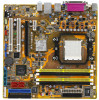
M2NPV-VM Motherboard - Asus M2NPV-VM | M2NPV-VM User's manual for English edition - Page 2
Product warranty or service will not be extended if: (1) the product is repaired, modified or altered, unless such repair, modification of alteration is authorized in writing by ASUS; or (2) the serial number of the product is defaced or missing. ASUS PROVIDES THIS MANUAL "AS IS" WITHOUT WARRANTY - Asus M2NPV-VM | M2NPV-VM User's manual for English edition - Page 3
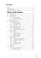
ASUS features 1-5 1.4 Before you proceed 1-7 1.5 Motherboard overview 1-8 1.5.1 Motherboard layout 1-8 1.5.2 Placement direction 1-9 1.5.3 Screw holes 1-9 1.6 Central Processing Unit (CPU 1-10 1.6.1 Installing the CPU 1-10 1.6.2 Installing the heatsink and fan 1-12 1.7 System memory - Asus M2NPV-VM | M2NPV-VM User's manual for English edition - Page 4
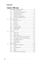
SATA Master 2-18 2.3.6 HDD SMART Monitoring 2-19 2.3.7 Installed Memory 2-19 2.3.8 Usable Memory 2-19 2.4 Advanced menu 2-20 2.4.1 JumperFree Configuration 2-20 2.4.2 AI NET2 2-22 2.4.3 CPU Configuration 2-22 2.4.4 Chipset 2-24 2.4.5 PCIPnP 2-25 2.4.6 Onboard Devices Configuration 2-26 iv - Asus M2NPV-VM | M2NPV-VM User's manual for English edition - Page 5
2-43 Chapter 3: Software support 3.1 Installing an operating system 3-2 3.2 Support CD information 3-2 3.2.1 Running the support CD 3-2 3.2.2 Drivers menu 3-3 3.2.3 Utilities menu 3-4 3.2.4 Make Disk menu 3-5 3.2.5 Manual menu 3-6 3.2.6 ASUS Contact information 3-7 3.2.7 Other information - Asus M2NPV-VM | M2NPV-VM User's manual for English edition - Page 6
tested and found to comply with the limits for a Class B digital device, pursuant to Part 15 of the FCC Rules. These limits are designed energy and, if not installed and used in accordance with manufacturer's instructions, may cause harmful interference to radio communications. However, there is no - Asus M2NPV-VM | M2NPV-VM User's manual for English edition - Page 7
service technician or your retailer. Operation safety • Before installing the motherboard and adding devices on it, carefully read all the manuals and staples away from connectors, slots, sockets and circuitry. • Avoid dust, technical problems with the product, contact a qualified service technician - Asus M2NPV-VM | M2NPV-VM User's manual for English edition - Page 8
M2NPV-VM specifications summary CPU Chipset Front Side Bus Memory Expansion slots Graphics Storage High Definition Audio LAN USB Support AMD socket AM2 for AMD Athlon™ 64FX/ Athlon™ 64 X2/Athlon™ 64/Sempron processors AMD64 architecture enables simultaneous 32-bit and 64-bit computing Supports AMD - Asus M2NPV-VM | M2NPV-VM User's manual for English edition - Page 9
400 MHz at 1 MHz increment N o t e : ASUS CrashFree BIOS 2 and ASUS EZ Flash 2 only support VGA/RGB output. BIOS features 4 Mb Flash ROM, Award BIOS, PnP, DMI2.0, WfM2.0, ACPI 2.0, SM BIOS 2.3 Rear panel 1 x Parallel port 1 x IEEE 1394a port 1 x LAN (RJ-45) port 4 x USB 2.0 ports 1 x VGA/RGB Out - Asus M2NPV-VM | M2NPV-VM User's manual for English edition - Page 10
M2NPV-VM specifications summary Power Requirement ATX power supply (with 24-pin and 4-pin 12 V plugs) ATX 12 V 2.0 compliant Form Factor uATX: 9.6 in. x 9.6 in. (24.5cm x 24.5cm) Support CD contents Device drivers ASUS PC Probe II AMD Cool 'n'Quiet™ utility ASUS Live Update utility Anti-virus - Asus M2NPV-VM | M2NPV-VM User's manual for English edition - Page 11
This chapter describes the motherboard features and the new technologies it supports. 1Product introduction - Asus M2NPV-VM | M2NPV-VM User's manual for English edition - Page 12
Documentation ASUS M2NPV-VM motherboard 2 x Serial ATA signal cables 1 x Serial ATA power cable for two Serial ATA devices 1 x IEEE 1394a module 1 x Ultra DMA 133/100/66 cable 1 x IDE cable 1 x Floppy disk drive cable I/O shield 1 x HDTV/AV/S output module ASUS motherboard support CD User guide If - Asus M2NPV-VM | M2NPV-VM User's manual for English edition - Page 13
that speeds up the PCI bus. PCI Express features point-to-point serial interconnections between devices and allows higher clockspeeds by carrying data in packets. This high speed interface is software compatible with existing PCI specifications. See page 1-19 for details. ASUS M2NPV-VM 1-3 - Asus M2NPV-VM | M2NPV-VM User's manual for English edition - Page 14
. See page 1-30 for details. HDTV output The motherboard features the NVIDIA® GeForce6150 chipset that supports superior HDTV-out functionality with a higher resolution to 1080i and 720p format, which are clearer than traditional formats allow. ASUS M2NPV-VM motherboard bundles a HDTV-out module - Asus M2NPV-VM | M2NPV-VM User's manual for English edition - Page 15
to restore the original BIOS data from the support CD in case when the BIOS codes and data are corrupted. This protection eliminates the need to buy a replacement BIOS chip. See page 2-10 for details. ASUS EZ Flash 2 With the ASUS EZ Flash, you can easily update the system BIOS even before loading - Asus M2NPV-VM | M2NPV-VM User's manual for English edition - Page 16
. Simply shut down and reboot the system, and the BIOS automatically restores the CPU default setting for each parameter. ASUS MyLogo™ This feature allows you to personalize and add style to your system with customizable boot logos. See page 2-37 for details. 1-6 Chapter 1: Product introduction - Asus M2NPV-VM | M2NPV-VM User's manual for English edition - Page 17
you install motherboard components or change any motherboard settings. • Unplug the power cord from the wall socket before motherboard component. The illustration below shows the location of the onboard LED. M2NPV-VM ® M2NPV-VM Onboard LED SB_PWR ON Standby Power OFF Powered Off ASUS M2NPV-VM - Asus M2NPV-VM | M2NPV-VM User's manual for English edition - Page 18
bit,240-pin module) Socket AM2 PARALLEL PORT VGA USBPW12 F_USB12 LAN_USB34 CHA_FAN1 USBPW34 Top:Line In Center:Line Out Bottom:Mic In 88E1116 AD 1986A CD TV_OUT PCIEX1_1 ® nVIDIA GeForce™6150 M2NPV-VM CHA_FAN2 PCIEX16 ® PCI1 SB_PWR TSB43AB22A ® nVIDIA nForce™430 PCI2 AAFP IE1394_1 - Asus M2NPV-VM | M2NPV-VM User's manual for English edition - Page 19
as indicated in the image below. 1.5.3 Screw holes Place eight (8) screws into the holes indicated by circles to secure the motherboard to the chassis. Do not overtighten the screws! Doing so can damage the motherboard. Place this side towards the rear of the chassis M2NPV-VM ® ASUS M2NPV-VM 1-9 - Asus M2NPV-VM | M2NPV-VM User's manual for English edition - Page 20
orientation. DO NOT force the CPU into the socket to prevent bending the connectors on the socket and damaging the CPU! 1.6.1 Installing the CPU To install a CPU. 1. Locate the CPU socket on the motherboard. M2NPV-VM ® M2NPV-VM CPU Socket AM2 2. Unlock the socket by pressing the lever sideways - Asus M2NPV-VM | M2NPV-VM User's manual for English edition - Page 21
Connect the CPU fan cable to the CPU_FAN connector on the motherboard. CPU_FAN CPU FAN PWM CPU FAN IN CPU FAN PWR GND M2NPV-VM ® M2NPV-VM CPU fan connector Do not forget to connect the CPU fan connector! Hardware monitoring errors can occur if you fail to plug this connector. ASUS M2NPV-VM 1-11 - Asus M2NPV-VM | M2NPV-VM User's manual for English edition - Page 22
• The retention module base is already installed on the motherboard upon purchase. • You do not have to remove the retention module base when installing the CPU or installing other motherboard components. • If you purchased a separate CPU heatsink and fan assembly, make sure that a Thermal Interface - Asus M2NPV-VM | M2NPV-VM User's manual for English edition - Page 23
of the retention bracket (near the retention bracket lock) to the retention module base. A clicking sound denotes that the retention bracket is in place. Make sure that the fan and heatsink assembly perfectly retention mechanism to secure the heatsink and fan to the module base. ASUS M2NPV-VM 1-13 - Asus M2NPV-VM | M2NPV-VM User's manual for English edition - Page 24
+ DIMM_B2) • Always install DIMMs with the same CAS latency. For optimum compatibility, we recommend that you obtain memory modules from the same vendor. Refer to the DDR2 Qualified Vendors List below for details. • Due to chipset resource allocation, the system may detect less than 8 GB system - Asus M2NPV-VM | M2NPV-VM User's manual for English edition - Page 25
into either the blue slots or the black slots as one pair of Dual-channel memory configuration. C - Supports 3 modules inserted into both the blue and black slots as two pairs of Dual-channel memory configuration. Visit the ASUS website for the latest DDR2-800/667 MHz QVL. ASUS M2NPV-VM 1-15 - Asus M2NPV-VM | M2NPV-VM User's manual for English edition - Page 26
both the motherboard and the components. 1. Unlock a DIMM socket by pressing the retaining clips outward. 2. Align a DIMM on the socket such into a socket to avoid damaging the DIMM. • The DDR2 DIMM sockets do not support DDR DIMMs. Do not install DDR DIMMs to the DDR2 DIMM sockets. 1.7.4 - Asus M2NPV-VM | M2NPV-VM User's manual for English edition - Page 27
cards that they support. Make sure unit cover (if your motherboard is already installed in a BIOS settings, if any. See Chapter 2 for information on BIOS setup. 2. Assign an IRQ to the card. Refer to the tables on the next page. 3. Install the software drivers for the expansion card. ASUS M2NPV-VM - Asus M2NPV-VM | M2NPV-VM User's manual for English edition - Page 28
CMOS/Real Time Clock IRQ holder for PCI steering* IRQ holder for PCI steering* IRQ holder for PCI steering* PS/2 Compatible Mouse Port* Numeric Data Processor Primary IDE Channel Secondary IDE Channel * These IRQs are usually available for ISA or PCI devices. IRQ assignments for this motherboard - Asus M2NPV-VM | M2NPV-VM User's manual for English edition - Page 29
following figure shows a network card installed on the PCI Express x1 slot. 1.8.5 PCI Express x16 slot This motherboard has supports PCI Express x16 graphic cards that comply with PCI Express specifications. The figure shows a graphics card installed on the PCI Express x16 slot. ASUS M2NPV-VM 1-19 - Asus M2NPV-VM | M2NPV-VM User's manual for English edition - Page 30
> key during the boot process and enter BIOS setup to re-enter data. Except when clearing the RTC RAM, never remove the cap on CLRTC jumper default position. Removing the cap will cause system boot failure! M2NPV-VM ® M2NPV-VM Clear RTC RAM CLRTC 12 23 Normal (Default) Clear CMOS You do not - Asus M2NPV-VM | M2NPV-VM User's manual for English edition - Page 31
The USB device wake-up feature requires a power supply that can provide 500mA on the +5VSB lead for each USB port; otherwise, the system will not power up. • The total current consumed must NOT exceed the power supply capability (+5VSB) whether under normal condition or in sleep mode. ASUS M2NPV-VM - Asus M2NPV-VM | M2NPV-VM User's manual for English edition - Page 32
Space Bar). This feature requires an ATX power supply that can supply at least 500 mA on the +5VSB lead, and a corresponding setting in the BIOS. KBPWR 2 1 +5V (Default) 3 2 +5VSB M2NPV-VM ® M2NPV-VM Keyboard power setting 1-22 Chapter 1: Product introduction - Asus M2NPV-VM | M2NPV-VM User's manual for English edition - Page 33
1394a port provides high-speed connectivity for audio/video devices, storage peripherals, PCs, or portable devices. 4 . L A N ( R J - 4 5 ) p o r t . This port allows Gigabit connection to a Local Area Network (LAN) through a network hub. LAN port LED indications ACT/LINK LED Status Description - Asus M2NPV-VM | M2NPV-VM User's manual for English edition - Page 34
for the function of the audio ports in 2, 4, or 6,-channel configuration. Audio 2, 4, or 6-channel USB) ports are available for connecting USB 2.0 devices. 1 0 . V i d e o G r a p h i c s A d a p t e r ( V G A ) p o r t . This 15-pin port is for a VGA monitor or other VGA-compatible devices - Asus M2NPV-VM | M2NPV-VM User's manual for English edition - Page 35
: Orient the red markings on the floppy ribbon cable to PIN 1. M2NPV-VM ® PIN 1 M2NPV-VM Floppy disk drive connector 2 . Chassis intrusion connector (4-1 pin CHASSIS) feature. +5VSB_MB Chassis Signal GND M2NPV-VM ® CHASSIS M2NPV-VM Chassis intrusion connector (Default) ASUS M2NPV-VM 1-25 - Asus M2NPV-VM | M2NPV-VM User's manual for English edition - Page 36
for Ultra DMA 133/100/66 IDE devices. If any device jumper is set as "Cable-Select," make sure all other device jumpers have the same setting. NOTE: Orient the red markings (usually zigzag) on the IDE ribbon cable to PIN 1. PRI_IDE SEC_IDE M2NPV-VM ® M2NPV-VM IDE connectors PIN 1 1-26 Chapter - Asus M2NPV-VM | M2NPV-VM User's manual for English edition - Page 37
of these connectors is set to [Disabled] by default. If you intend to create a Serial ATA RAID set using these connectors, enable the R A I D E n a b l e d item in the NVRAID Configuration sub-menu in the BIOS. See section "2.4.6 Onboard Device Configuration" for details. ASUS M2NPV-VM 1-27 - Asus M2NPV-VM | M2NPV-VM User's manual for English edition - Page 38
damage the motherboard components. These are not jumpers! DO NOT place jumper caps on the fan connectors. Only CPU Fan and Chassis Fan1, Fan2 support Q-Fan 2. PWR_FAN CPU_FAN PWR_FAN CPU_FAN GND +12V Rotation CPU FAN PWM CPU FAN IN CPU FAN PWR GND CHA_FAN1 M2NPV-VM ® CHA_FAN2 M2NPV-VM Fan - Asus M2NPV-VM | M2NPV-VM User's manual for English edition - Page 39
the motherboard! The USB 2.0 module is purchased separately. 8 . Optical drive audio in connector (4-pin CD) These connectors allow you to receive stereo audio input from sound sources such as a CD-ROM, TV tuner, or MPEG card. Right Audio Channel Ground Ground Left Audio Channel M2NPV-VM ® CD - Asus M2NPV-VM | M2NPV-VM User's manual for English edition - Page 40
USB/GAME module cable to this connector, then install the module to a slot opening at the back of the system chassis. The GAME/MIDI port connects a joystick or game pad for playing games, and MIDI devices for playing or editing audio files. M2NPV-VM ® M2NPV-VM GND M2NPV-VM ® IE1394_1 1 M2NPV-VM - Asus M2NPV-VM | M2NPV-VM User's manual for English edition - Page 41
panel audio module to this connector to avail of the motherboard high-definition audio capability. • If you want to connect a high-definition front panel audio module to this connector, make sure that the H D A u d i o item in the BIOS is set to [Enabled]. See page 2-28 for details. ASUS M2NPV-VM - Asus M2NPV-VM | M2NPV-VM User's manual for English edition - Page 42
your system. Connect one end of the HDTV-out cable to this connector and the other end to the TV-out module. Pb PR Y +12V M2NPV-VM ® TV_OUT GND GND +5V M2NPV-VM TV out connector • RGB and TV-out can not be used simultaneously. 1-32 Chapter 1: Product introduction - Asus M2NPV-VM | M2NPV-VM User's manual for English edition - Page 43
. The system may become unstable or may not boot up if the power is inadequate. • You must install a PSU with a higher power rating if you intend to install additional devices. EATXPWR M2NPV-VM ® ATX12V GND +12V DC GND +12V DC M2NPV-VM ATX power connectors +3 Volts -12 Volts Ground PSON - Asus M2NPV-VM | M2NPV-VM User's manual for English edition - Page 44
supports several chassis-mounted functions. PWR LED SPKR PLED+ PLED+5V Ground Ground Speaker PANEL IDE_LED+ IDE_LED- PWR Ground Reset Ground M2NPV-VM ® M2NPV-VM speaker allows you to hear system beeps and warnings. • Power/Soft -OFF mode depending on the BIOS settings. Pressing the power switch - Asus M2NPV-VM | M2NPV-VM User's manual for English edition - Page 45
This chapter tells how to change the system settings through the BIOS Setup menus. Detailed descriptions of the BIOS parameters are also provided. 2 BIOS setup - Asus M2NPV-VM | M2NPV-VM User's manual for English edition - Page 46
• View the BIOS version information. This utility is available in the support CD that comes with the motherboard package. ASUS Update requires an Internet connection either through a network or an Internet Service Provider (ISP). Installing ASUS Update To install ASUS Update: 1. Place the support CD - Asus M2NPV-VM | M2NPV-VM User's manual for English edition - Page 47
U p d a t e. The ASUS Update main window appears. 2. Select U p d a t e B I O S f r o m 3. Select the ASUS FTP site t h e I n t e r n e t option from the nearest you to avoid network drop-down menu, then click traffic, or click A u t o S e l e c t. N e x t. Click N e x t. ASUS M2NPV-VM 2-3 - Asus M2NPV-VM | M2NPV-VM User's manual for English edition - Page 48
to download. Click Next. 5. Follow the screen instructions to complete the update process. The ASUS Update utility is capable of updating itself through the Internet. Always update the utility to avail all its features. Updating the BIOS through a BIOS file To update the BIOS through a BIOS file - Asus M2NPV-VM | M2NPV-VM User's manual for English edition - Page 49
Windows® 2000 environment To create a set of boot disks for Windows® 2000: a. Insert a formatted, high density 1.44 MB floppy disk into the drive. b. Insert the Windows instructions to continue. 2. Copy the original or the latest motherboard BIOS file to the bootable floppy disk. ASUS M2NPV-VM - Asus M2NPV-VM | M2NPV-VM User's manual for English edition - Page 50
(POST). To update the BIOS using EZ Flash 2: 1. Visit the ASUS website (www.asus.com) to download the latest BIOS file for the motherboard. 2. Save the BIOS file to a floppy disk, then restart the system. 3. You can launch the EZ Flash 2 by two methods. (1) Insert the floppy disk/USB flash disk that - Asus M2NPV-VM | M2NPV-VM User's manual for English edition - Page 51
2.1.4 Updating the BIOS The Basic Input/Output System (BIOS) can be updated using the AwardBIOS Flash Utility. Follow these instructions to update the BIOS using this utility. 1. Download the latest BIOS file from the ASUS web site. Rename the file to M 2 N P V - V M . B I N and save it to a floppy - Asus M2NPV-VM | M2NPV-VM User's manual for English edition - Page 52
The following screen appears. 8. The utility verifies the BIOS file in the floppy disk, CD ROM or a USB flash disk and starts flashing the BIOS file. AwardBIOS Flash Utility for ASUS V1.17 (C) Phoenix Technologies Ltd. All Rights Reserved For C51PV-MCP51-M2NPV-VM-00 DATE: 04/13/2006 Flash Type - Asus M2NPV-VM | M2NPV-VM User's manual for English edition - Page 53
Phoenix Technologies Ltd. All Rights Reserved floppy disk, then returns For C51PV-MCP51-M2NPV-VM-00 DATE: 04/13/2006 to the BIOS flashing Flash Type - PMC Pm49FL004T LPC/FWH process. File Name to Program: 0107 .bin Now Backup Syetem BIOS to File! Message: Please wait... ASUS M2NPV-VM 2-9 - Asus M2NPV-VM | M2NPV-VM User's manual for English edition - Page 54
2 utility The ASUS CrashFree BIOS 2 is an auto recovery tool that allows you to restore the BIOS file when it fails or gets corrupted during the updating process. You can update a corrupted BIOS file using the motherboard support CD or the floppy disk that contains the updated BIOS file. • Prepare - Asus M2NPV-VM | M2NPV-VM User's manual for English edition - Page 55
the Exit Menu. See section "2.8 Exit Menu." • The BIOS setup screens shown in this section are for reference purposes only, and may not exactly match what you see on your screen. • Visit the ASUS website (www.asus.com) to download the latest BIOS file for this motherboard and . ASUS M2NPV-VM 2-11 - Asus M2NPV-VM | M2NPV-VM User's manual for English edition - Page 56
Phoenix-Award BIOS CMOS Setup Utility Main Advanced Power Boot Tools Exit ASUS CDS520/A] [None] [None] [None] [None] [None] [None] [Disabled] Change the day, month, year and century. Installed Memory Usable Memory boot configuration item is highlighted. • The BIOS setup screens shown in this chapter - Asus M2NPV-VM | M2NPV-VM User's manual for English edition - Page 57
Loads setup default values Exits the BIOS setup or returns to the main menu from a sub- shows the Main menu items. The other items (Advanced, Power, Boot, and Exit) on the menu bar have their respective menu items. list of options. Refer to "2.2.7 Pop-up window." ASUS M2NPV-VM 2-13 - Asus M2NPV-VM | M2NPV-VM User's manual for English edition - Page 58
display a pop-up window with the configuration options for that item. Phoenix-Award BIOS CMOS Setup Utility Main Advanced Power Boot Tools Exit System in[.None] ..... [ ] HDD SMART Monitoring [Disabled] Installed Memory ↑↓ :Move ENTER2:5A6cMcBept ESC:Abort Select Menu Item Specific Help - Asus M2NPV-VM | M2NPV-VM User's manual for English edition - Page 59
. Phoenix-Award BIOS CMOS Setup Utility Main Advanced Power Boot Tools Exit System ASUS CDS520/A] [None] [None] [None] [None] [None] [None] [Disabled] Select Menu Item Specific Help Change the day, month, year and century. Installed Memory Usable Memory in.] [1.44M, 3.5 in.] ASUS M2NPV-VM 2-15 - Asus M2NPV-VM | M2NPV-VM User's manual for English edition - Page 60
BIOS automatically detects the presence of IDE devices. There is a separate sub-menu for each IDE device. Select a device item then press to display the IDE device information. Main Phoenix-Award BIOS CMOS to [Manual]. Configuration fail to recognize the installed hard disk. 2-16 Chapter - Asus M2NPV-VM | M2NPV-VM User's manual for English edition - Page 61
for the IDE device. Configuration options: BIOS, use a disk utility, such as FDISK, to partition and format new IDE hard disk drives. This is necessary so that you can write or read data from the hard disk. Make sure to set the partition of the Primary IDE hard disk drives to active. ASUS M2NPV-VM - Asus M2NPV-VM | M2NPV-VM User's manual for English edition - Page 62
BIOS automatically detects the presence of Serial ATA devices. There is a separate sub-menu for each SATA device. Select a device item then press to display the SATA device information. Main Phoenix-Award BIOS CMOS settings may cause the system to fail to recognize the installed hard disk. - Asus M2NPV-VM | M2NPV-VM User's manual for English edition - Page 63
This item is not configurable. After entering the IDE hard disk drive information into BIOS, use a disk utility, such as FDISK, to partition and format new IDE Installed Memory [xxx MB] Shows the size of installed memory. 2.3.8 Usable Memory [XXX MB] Shows the size of usable memory. ASUS M2NPV-VM - Asus M2NPV-VM | M2NPV-VM User's manual for English edition - Page 64
-Award BIOS CMOS Setup Utility Main Advanced Power Boot Exit JumperFree Configuration AI NET2 CPU Configuration Chipset PCIPnP Onboard Device Configuration CPU overclocking options to achieve desired CPU internal frequency. Selct either one of the preset overclocking configuration options: Manual - Asus M2NPV-VM | M2NPV-VM User's manual for English edition - Page 65
n g to [Manual]. CPU Frequency [XXX] ( CPU speed. The BIOS auto-detects the value of CPU Multiplier [Auto] Allows you to set the operating CPU multiplier. The configuration options may vary depending on the type of CPU installed. Configuration options: [Auto] [5x] [5.5x] [6x] ~ [12x] ASUS M2NPV-VM - Asus M2NPV-VM | M2NPV-VM User's manual for English edition - Page 66
or disables checking of the LAN/LAN2 cable during the Power-On Self-Test (POST). Configuration options: [Disabled] [Enabled] 2.4.3 CPU Configuration Advanced Phoenix-Award BIOS CMOS Setup Utility CPU Configuration CPU Type AMD Engineering Sample CPU Speed 2600MHz Cache RAM 1024K DRAM - Asus M2NPV-VM | M2NPV-VM User's manual for English edition - Page 67
[Auto] Configuration options: [Auto] [2] [3] [4] ~ [9] 1T/2T Memory Timing [Auto] Configuration options: [Auto] [1T] [2T] Memory Hole Remapping [Enabled] Configuration options: [Disabled] [Enabled] Bottom of 32/ Cool 'n' Quiet technology. Configuration options: [Auto] [Disabled] ASUS M2NPV-VM 2-23 - Asus M2NPV-VM | M2NPV-VM User's manual for English edition - Page 68
BIOS CMOS Setup Utility Frame Buffer Size ECC Spread Spectrum PCIE Spread Spectrum SATA Spread Spectrum HT Spread Spectrum RGB/TV Display TV Mode Support Chipset ] Spread Spectrum [Down] Enables or disables Spread Spectrum for CPU. Configuration options: [Disabled] [Center] [Down] PCIE Spread - Asus M2NPV-VM | M2NPV-VM User's manual for English edition - Page 69
Controlled By [Auto] When set to [Auto], the BIOS automatically configures all the boot and Plug and Play compatible devices. Set to [Manual] if you want to assign the IRQ DMA and memory base address fields. Configuration options: [Auto] [Manual] When the item Resources Controlled By is set to - Asus M2NPV-VM | M2NPV-VM User's manual for English edition - Page 70
] [512] [1024] [2048] [4096] 2.4.6 Onboard Devices Configuration Advanced Phoenix-Award BIOS CMOS Setup Utility Onboard Device Configuration IDE Function Setup NVRAID Configuration USB Configuration Onboard NV LAN Onboard LAN Boot ROM Onboard IEEE 1394 HD Audio Serial Port1 Address Serial Port2 - Asus M2NPV-VM | M2NPV-VM User's manual for English edition - Page 71
Disabled Disabled Disabled Disabled Item Specific Help Disable/Enable nVIDIA RIAD feature. RAID Enabled [Disabled] Enables or disables the onboard RAID controller. When set to [Enabled], the succeeding items become user-configurable. Configuration options: [Disabled] [Enabled] ASUS M2NPV-VM 2-27 - Asus M2NPV-VM | M2NPV-VM User's manual for English edition - Page 72
you to enable or disable support for USB devices on legacy operating systems (OS). Configuration options: [Disabled] [Enabled] Onboard NV LAN [Enabled] Enables or disables the onboard NVIDIA® LAN controller. Configuration options: [Disabled] [Enabled] OnBoard LAN Boot ROM [Disabled] Allows you to - Asus M2NPV-VM | M2NPV-VM User's manual for English edition - Page 73
or to disable the port. Configuration options: [Disabled] [330] [300] Midi Port IRQ [10] Allows you to select the Midi Port IRQ. Configuration options: [5] [10] ASUS M2NPV-VM 2-29 - Asus M2NPV-VM | M2NPV-VM User's manual for English edition - Page 74
Power Management (APM). Select an item then press to display the configuration options. Phoenix-Award BIOS CMOS Setup Utility Main Advanced Power Boot Exit ACPI Suspend Type ACPI APIC support APM Configuration Hardware Monitor [S1&S3] [Enabled] Select Menu Item Specific Help Select the - Asus M2NPV-VM | M2NPV-VM User's manual for English edition - Page 75
Allows you to enable or disable the PME to wake up from S5 by PCI/PCIE devices & NV Onboard LAN. Configuration options: [Disabled] [Enabled] Power On By External Modems [Disabled] This allows either the specified range then press . Configuration options: [Min=0] [Max=31] ASUS M2NPV-VM 2-31 - Asus M2NPV-VM | M2NPV-VM User's manual for English edition - Page 76
requires an ATX power supply that provides at least 1A on the +5VSB lead. Configuration options: [Disabled] [Space Bar] [Ctrl-ESC] [Power Key] 2-32 Chapter 2: BIOS setup - Asus M2NPV-VM | M2NPV-VM User's manual for English edition - Page 77
in rotations per minute (RPM). If any of the fans is not connected to the motherboard, the field shows 0. These items are not user-configurable. CPU Fan Speed warning [800 RPM] Sets the CPU fan speed warning feature. Configuration options: [Disabled] [800RPM] [1200RPM] [1600RPM] ASUS M2NPV-VM 2-33 - Asus M2NPV-VM | M2NPV-VM User's manual for English edition - Page 78
that appears on the screen depends on the number of devices installed in the system. Configuration options: [Removable] [Hard Disk] [CDROM] [Legacy LAN] [Disabled] 2.6.2 Removable Drives Phoenix-Award BIOS CMOS Setup Utility Boot Removable Drives Select Menu 1. Floppy Disks Item Specific Help - Asus M2NPV-VM | M2NPV-VM User's manual for English edition - Page 79
bootable add-in cards attached to the system. 2.6.4 CDROM Drives Phoenix-Award BIOS CMOS Setup Utility Boot CDROM Drives Select Menu 1. 2nd Slave: XXXXXXXXX Item Specific Help 1. 2nd Slave -/+: Change Value F5: Setup Defaults Enter: Select SubMenu F10: Save and Exit ASUS M2NPV-VM 2-35 - Asus M2NPV-VM | M2NPV-VM User's manual for English edition - Page 80
section "1.10.2 Internal connectors" for setting details. Configuration options: [Disabled] [Enabled] Quick Boot [Enabled] Allows you to enable or disable the system quick boot feature. When Enabled, the system skips than 64 KB. Configuration options: [Non-OS2] [OS2] 2-36 Chapter 2: BIOS setup - Asus M2NPV-VM | M2NPV-VM User's manual for English edition - Page 81
] [Enabled] Make sure that the above item is set to [Enabled] if you want to use the ASUS MyLogo™ feature. Halt On [All, But Keyboard] Allows you to error report type. Configuration options: [All Errors] [No Errors] [All, But Keyboard] [All, But Diskette] [All, But Disk/Key] ASUS M2NPV-VM 2-37 - Asus M2NPV-VM | M2NPV-VM User's manual for English edition - Page 82
you forget your password, you can clear it by erasing the CMOS Real Time Clock (RTC) RAM. The RAM data containing the password information is powered by the onboard button cell battery. If you need to erase the CMOS RAM, refer to section "1.9 Jumpers" for instructions. 2-38 Chapter 2: BIOS setup - Asus M2NPV-VM | M2NPV-VM User's manual for English edition - Page 83
Check This field requires you to enter the password before entering the BIOS setup or the system. Select [Setup] to require the password before entering the BIOS Setup. Select [System] to require the password before entering the system. Configuration options: [Setup] [System] ASUS M2NPV-VM 2-39 - Asus M2NPV-VM | M2NPV-VM User's manual for English edition - Page 84
menu. Phoenix-Award BIOS CMOS Setup Utility Main Advanced Power Boot Tools Exit ASUS O.C. Profile EZ BIOS files saved in the hard disk/floppy disk/USB flash disk with the FAT32/16/12 format. Follow the instructions below to load the BIOS file. 1. Insert the storage devices that contain the "xxx.CMO - Asus M2NPV-VM | M2NPV-VM User's manual for English edition - Page 85
will inform you when the loading process finishes. • Suggest only to update the BIOS file coming from the same memory/CPU configuration and BIOS version. • Only the "xxx.CMO" file can be loaded. Save BIOS Profile Phoenix-Award BIOS CMOS Setup Utility Tools Save to Profile 1 Save to Profile 2 Save - Asus M2NPV-VM | M2NPV-VM User's manual for English edition - Page 86
section 2.1.3 for details. ASUSTek EZ Flash 2 BIOS RROM Utility B311 FLASH TYPE: Winbond W39V080A 8Mb LPC Current ROM BOARD: M2NPV VM VER: 0122 DATE: 04/24/2006 Update ROM BOARD: Unknown VER: Unknown DATE: Unknown PATH: C:\M2NPVOC A: WIN98ESE C: NETTERM DRIVERS RECYCLED WUTEMP NEWFOL - Asus M2NPV-VM | M2NPV-VM User's manual for English edition - Page 87
or failsafe default values for the BIOS items, and save or discard your changes to the BIOS items. Phoenix-Award BIOS CMOS Setup Utility Main Advanced Power Boot Tools Exit Exit & Save System Date, System Time, and Password, the BIOS asks for a confirmation before exiting. ASUS M2NPV-VM 2-43 - Asus M2NPV-VM | M2NPV-VM User's manual for English edition - Page 88
values for each of the parameters on the Setup menus. When you select this option or if you press , a confirmation window appears. Select Y E S to load default values. Select E x i t & S a v e C h a n to discard any changes and load the previously saved values. 2-44 Chapter 2: BIOS setup - Asus M2NPV-VM | M2NPV-VM User's manual for English edition - Page 89
This chapter describes the contents of the support CD that comes with the motherboard package. 3 Software support - Asus M2NPV-VM | M2NPV-VM User's manual for English edition - Page 90
to your OS documentation for detailed information. • Make sure that you install Windows® 2000 Service Pack 4 or the Windows® XP Service Pack 1 or later versions before installing the drivers for better compatibility and system stability. 3.2 Support CD information The support CD that came with the - Asus M2NPV-VM | M2NPV-VM User's manual for English edition - Page 91
wizard to install the SoundMAX™ AD1986A audio driver and application. AMD Cool 'n' Quiet Driver Installs the AMD Cool 'n' Quiet driver. USB 2.0 Driver Installs the USB 2.0 driver. The screen display and drivers option may not be the same for different operating system versions. ASUS M2NPV-VM 3-3 - Asus M2NPV-VM | M2NPV-VM User's manual for English edition - Page 92
detected problems. This utility helps you keep your computer in healthy operating condition. ASUS Update The ASUS Update utility allows you to update the motherboard BIOS in a Windows® environment. This utility requires an Internet connection either through a network or an Internet Service Provider - Asus M2NPV-VM | M2NPV-VM User's manual for English edition - Page 93
. NVIDIA® 32bit Win2K SATA RAID Driver Allows you to create an NVIDIA® Windows® 2000 Serial ATA (SATA) RAID driver disk for a 32-bit system. NVIDIA® 32bit WinXP SATA RAID Driver Allows you to create an NVIDIA® Windows® XP Serial ATA (SATA) RAID driver disk for a 32-bit system. ASUS M2NPV-VM 3-5 - Asus M2NPV-VM | M2NPV-VM User's manual for English edition - Page 94
64bit SATA RAID Driver Allows you to create an NVIDIA® Serial ATA (SATA) RAID driver disk for a 64-bit system. 3.2.5 Manual menu The Manual menu contains a list of supplementary user manuals. Click an item to open the folder of the user manual. Most user manual files are in Portable Document Format - Asus M2NPV-VM | M2NPV-VM User's manual for English edition - Page 95
guide. 3.2.7 Other information The icons on the top right corner of the screen give additional information on the motherboard and the contents of the support CD. Click an icon to display the specified information. Motherboard Info Displays the general specifications of the motherboard. ASUS M2NPV - Asus M2NPV-VM | M2NPV-VM User's manual for English edition - Page 96
Browse this CD Displays the support CD contents in graphical format. Technical support Form Displays the ASUS Technical Support Request Form that you have to fill out when requesting technical support. Filelist Displays the contents of the support CD and a brief description of each in text format.
-
 1
1 -
 2
2 -
 3
3 -
 4
4 -
 5
5 -
 6
6 -
 7
7 -
8
-
9
-
10
-
11
-
12
-
13
-
14
-
15
-
16
-
17
-
18
-
19
-
20
-
21
-
22
-
23
-
24
-
25
-
26
-
27
-
28
-
29
-
30
-
31
-
32
-
33
-
34
-
35
-
36
-
37
-
38
-
39
-
40
-
41
-
42
-
43
-
44
-
45
-
46
-
47
-
48
-
49
-
50
-
51
-
52
-
53
-
54
-
55
-
56
-
57
-
58
-
59
-
60
-
61
-
62
-
63
-
64
-
65
-
66
-
67
-
68
-
69
-
70
-
71
-
72
-
73
-
74
-
75
-
76
-
77
-
78
-
79
-
80
-
81
-
82
-
83
-
84
-
85
-
86
-
87
-
88
-
89
-
90
-
91
-
92
-
93
-
94
-
95
-
96
 |
 |

Motherboard
M2NPV-VM