Asus M3N72-D User Manual
Asus M3N72-D - Motherboard - ATX Manual
 |
UPC - 610839163670
View all Asus M3N72-D manuals
Add to My Manuals
Save this manual to your list of manuals |
Asus M3N72-D manual content summary:
- Asus M3N72-D | User Manual - Page 1
M3N72-D Motherboard - Asus M3N72-D | User Manual - Page 2
express written permission of ASUSTeK COMPUTER INC. ("ASUS"). Product warranty or service will not be extended if: (1) the ASUS HAS BEEN ADVISED OF THE POSSIBILITY OF SUCH DAMAGES ARISING FROM ANY DEFECT OR ERROR IN THIS MANUAL OR PRODUCT. SPECIFICATIONS AND INFORMATION CONTAINED IN THIS MANUAL - Asus M3N72-D | User Manual - Page 3
viii About this guide ix M3N72-D specifications summary xi Chapter 1: Product introduction 1.1 Welcome 1-1 1.2 Package contents 1-1 1.3 Special features 1-2 1.3.1 Product highlights 1-2 1.3.2 ASUS unique features 1-4 1.3.3 ASUS intelligent performance and overclocking features 1-6 Chapter - Asus M3N72-D | User Manual - Page 4
panel connectors 2-26 2.7.2 Internal connectors 2-29 Chapter 3: Powering up 3.1 Starting up for the first time 3-1 3.2 Turning off the computer 3-2 3.2.1 Using the OS shut down function 3-2 3.2.2 Using the dual function power switch 3-2 Chapter 4: BIOS setup 4.1 Managing and updating your BIOS - Asus M3N72-D | User Manual - Page 5
Exit menu 4-37 Chapter 5: Software support 5.1 Installing an operating system 5-1 5.2 Support DVD information 5-1 5.2.1 Running the support DVD 5-1 5.2.2 Drivers menu 5-2 5.2.3 Utilities menu 5-3 5.2.4 Make Disk menu 5-5 5.2.5 Manual menu 5-6 5.2.6 ASUS Contact information 5-6 5.2.7 Other - Asus M3N72-D | User Manual - Page 6
5-42 5.4.1 RAID definitions 5-42 5.4.2 NVIDIA® RAID configurations 5-43 5.5 Creating a RAID driver disk 5-50 5.5.1 Creating a RAID driver disk without entering the OS.... 5-50 5.5.2 Creating a RAID/SATA driver disk in Windows 5-50 Chapter 6: NVIDIA® Hybrid SLI™ technology support 6.1 NVIDIA® SLI - Asus M3N72-D | User Manual - Page 7
, if not installed and used in accordance with manufacturer's instructions, may cause harmful interference to radio communications. However, there the receiver is connected. • Consult the dealer or an experienced radio/TV technician for help. The use of shielded cables for connection of the monitor - Asus M3N72-D | User Manual - Page 8
away from connectors, slots, sockets and circuitry. • Avoid dust, humidity, and temperature extremes. Do not place the product in any area where it may become wet. • Place the product on a stable surface. • If you encounter technical problems with the product, contact a qualified service technician - Asus M3N72-D | User Manual - Page 9
descriptions of the BIOS parameters are also provided. • Chapter 5: Software support This chapter describes the contents of the support DVD that comes with the motherboard package and the software. • Chapter 6: nVIDIA Hybrid SLI™ support This chapter describes the nVIDIA Hybrid SLI™ feature and - Asus M3N72-D | User Manual - Page 10
the following symbols used throughout this manual. DANGER/WARNING: Information to prevent injury to yourself when trying to complete a task. CAUTION: Information to prevent damage to the components when trying to complete a task. IMPORTANT: Instructions that you MUST follow to complete - Asus M3N72-D | User Manual - Page 11
M3N72-D specifications summary CPU Chipset System bus Memory VGA Expansion slots Storage LAN High Definition audio AMD® Socket AM2/AM2+ for Phenom™ FX / Phenom™ / Athlon™ / Sempron™ processors AMD Cool 'n' Quiet™ Technology AMD Live!™ Ready Supports CPU TDP up to 140W NVIDIA® nForce 750a SLI Up to - Asus M3N72-D | User Manual - Page 12
M3N72-D specifications summary IEEE 1394 USB ASUS unique features Other features ASUS exclusive overclocking features LSI® FW322 controller supports 2 x IEEE 1394a ports (1 at mid-board; 1 on the rear panel) 12 x USB 2.0 ports (6 at mid-board; 6 on the rear panel) ASUS Express Gate: - Web browser, - Asus M3N72-D | User Manual - Page 13
I/O connectors 3 x USB connectors support additional 6 USB ports 1 x Floppy disk drive connector 1 x COM connector 1 x VGA connector 1 x IDE connector 6 x SATA connectors 1 x CPU Fan connector 1 x Chassis Fan connector 1 x Power Fan connector 1 x IEEE1394a connector 1 x Front panel audio connector - Asus M3N72-D | User Manual - Page 14
xiv - Asus M3N72-D | User Manual - Page 15
This chapter describes the motherboard features and the new technologies it supports. Chapter 1: 1Product introduction - Asus M3N72-D | User Manual - Page 16
Chapter summary 1 1.1 Welcome 1-1 1.2 Package contents 1-1 1.3 Special features 1-2 ASUS M3N72-D - Asus M3N72-D | User Manual - Page 17
, system panel; Retail version only) 1 x D-Sub connector module 1 x HDMI to DVI converter 1 x SLI bridge 1 x USB module (2 USB 2.0 ports) Application DVD ASUS motherboard support DVD Documentation User guide If any of the above items is damaged or missing, contact your retailer. ASUS M3N72 - Asus M3N72-D | User Manual - Page 18
™ CPU support This motherboard supports AMD® Socket AM2 Athlon™ Series / Sempron™ processors. It features 2000/1600 MT/s HyperTransport™-based system bus, dual-channel un-buffered DDR2 800 memory support, and AMD® Cool 'n' Quiet™ Technology. See page 2-6 for details. NVIDIA® nForce 750a Chipset - Asus M3N72-D | User Manual - Page 19
on the Serial ATA (SATA) 3Gb/s storage specifications, delivering enhanced scalability and doubling the bus bandwidth for high-speed data retrieval and save. It allows RAID 0, 1, 0+1 and 5 configurations for two SATA connectors. See page 2-31 for details. IEEE 1394a support The IEEE 1394a interface - Asus M3N72-D | User Manual - Page 20
Gate supports installation on USB devices or SATA HDDs in IDE mode only. ASUS Quiet Thermal Solution ASUS Quiet Thermal solution makes system more stable and enhances the overclocking capability. AI Gear 2 AI Gear 2 allows you to choose from profiles to adjust CPU frequency and vCore voltage - Asus M3N72-D | User Manual - Page 21
connect or disconnect the chassis front panel cables to the motherboard. This unique module eliminates the trouble of connecting the system panel cables one at a time and avoiding wrong cable connections. See page 2-41 for details. ASUS EZ Flash 2 ASUS EZ Flash 2 is a user-friendly BIOS update - Asus M3N72-D | User Manual - Page 22
maximum system performance. AI Booster The ASUS AI Booster allows you to overclock the CPU speed in Windows environment without the hassle of booting the BIOS. See page 5-33 for details. C.P.R. (CPU Parameter Recall) The C.P.R. feature of the motherboard BIOS allows automatic re-setting to the - Asus M3N72-D | User Manual - Page 23
This chapter lists the hardware setup procedures that you have to perform when installing system components. It includes description of the jumpers and connectors on the motherboard. Chapter 2: 2 Hardware information - Asus M3N72-D | User Manual - Page 24
Chapter summary 2 2.1 Before you proceed 2-1 2.2 Motherboard overview 2-2 2.3 Central Processing Unit (CPU 2-6 2.4 System memory 2-11 2.5 Expansion slots 2-21 2.6 Jumper 2-25 2.7 Connectors 2-26 ASUS M3N72-D - Asus M3N72-D | User Manual - Page 25
up to indicate that the system is ON, in sleep mode, or in soft‑off mode. This is a reminder that you should shut down the system and unplug the power cable before removing or plugging in any motherboard component. The illustration below shows the location of the onboard LED. ASUS M3N72-D 2-1 - Asus M3N72-D | User Manual - Page 26
it. Make sure to unplug the power cord before installing or removing the motherboard. Failure to do so can cause you physical injury and damage motherboard components. 2.2.1 Placement direction When installing the motherboard, make sure that you place it into the chassis in the correct orientation - Asus M3N72-D | User Manual - Page 27
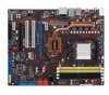
2.2.3 Motherboard layout Refer to 2.7 Connectors for more information about rear panel connectors and internal connectors. ASUS M3N72-D 2-3 - Asus M3N72-D | User Manual - Page 28
Express x1 slots PCI Express 2.0 x16 slot (blue) Universal PCI Express x16 slot (black) Jumper Clear RTC RAM (3-pin CLRTC) Rear panel connectors 1 P�S�/2��k�e�yb�o�a�r�d�p�o�r�t �(p�u�r�p�le�) 2. IEEE 1394a port 3. LAN (RJ-45) port. 4. Center/Subwoofer port (orange) 5. Rear Speaker Out - Asus M3N72-D | User Manual - Page 29
Front panel audio connector (10-1 pin AAFP) 10. Optical drive audio connector (4-pin CD) 11. Serial port connector (10-1 pin COM1) 12. Digital audio connector (4-1 pin SPDIF_OUT) 13. Video Graphics Adapter (VGA) connector (16-pin VGA) 14. System panel connector (20-8-pin PANEL) 15. ASUS - Asus M3N72-D | User Manual - Page 30
for the AM2+/AM2 socket. The CPU fits in only one correct orientation. DO NOT force the CPU into the socket to prevent bending the connectors on the socket and damaging the CPU! 2.3.1 Installing the CPU To install a CPU: 1. Locate the CPU socket on the motherboard. 2. Unlock the socket by pressing - Asus M3N72-D | User Manual - Page 31
fits in place. Gold triangle Small triangle 5. When the CPU is in place, push down the socket lever to secure the CPU. The lever clicks on the side tab to indicate that it is locked. 6. Install a CPU heatsink and fan following the instructions that came with the heatsink package. ASUS M3N72-D 2-7 - Asus M3N72-D | User Manual - Page 32
you use only AMD-certified heatsink and fan assembly. To install the CPU heatsink and fan: 1. Place the heatsink on top of the installed CPU, making sure that the heatsink fits properly on the retention module base. • The retention module base is already installed on the motherboard upon purchase - Asus M3N72-D | User Manual - Page 33
the retention bracket in place. 4. Push down the retention bracket lock on the retention mechanism to secure the heatsink and fan to the module base. ASUS M3N72-D 2-9 - Asus M3N72-D | User Manual - Page 34
the fan and heatsink assembly is in place, connect the CPU fan cable to the connector on the motherboard labeled CPU_FAN. • Do not forget to connect the CPU fan connector! Hardware monitoring errors can occur if you fail to plug this connector. • This connector is backward compatiable with old 3-pin - Asus M3N72-D | User Manual - Page 35
2.4 System memory 2.4.1 Overview The motherboard comes with four Double Data Rate 2 (DDR2) Dual Inline Memory Modules (DIMM) sockets. The figure illustrates the location of the DDR2 DIMM sockets: Channel Channel A Channel B Sockets DIMM_A1 and DIMM_A2 DIMM_B1 and DIMM_B2 ASUS M3N72-D 2-11 - Asus M3N72-D | User Manual - Page 36
• If you install Windows® XP/Vista 32-bit operation system, a total memory of less than 3GB is recommended. • This motherboard does not support memory modules made up of 128 Mb chips. Due to OS limitation, this motherboard can only support up to 16 GB on the operating systems listed below. You may - Asus M3N72-D | User Manual - Page 37
socket support (Optional) A* B* C* Box P/N:TWIN2X4096-8500C5DF • (CM2X2048-8500C5D)(EPP) F2-8500CL5D-2GBPK • • • F2-8500CL5D-4GBPK • • • HYS64T64000EU-19F-C • M3N78 PRO Motherboard Qualified Vendors Lists (QVL) DDR2-800MHz capability for AM2+ CPU HYMP512U64CP8-S5 • • ASUS M3N72-D 2-13 - Asus M3N72-D | User Manual - Page 38
M3N78 PRO Motherboard Qualified Vendors Lists (QVL) DDR2-800MHz capability for AM2+ CPU (cont.) Size Vendor Chip No. / DS Part No. SS KLDC28F-A8KI5 DS KLDD48F-ABKI5 SS KVR800D2N5/512 SS KHX6400D2LLK2/1GN DIMM socket support (Optional) A* B* C* • • • • • • • • • • DS KHX6400D2LL/1G - Asus M3N72-D | User Manual - Page 39
DS PSD22GB002 DS D48001GP3-63BJU DS D48002GP0-73BCU DIMM socket support (Optional) A* B* C* • • • • • • • • • • • • • • • • • • • • • • • • M3N78 PRO Motherboard Qualified Vendors Lists (QVL) DDR2-667MHz capability for AM2+ CPU Size Vendor Chip No. CL Chip Brand SS - Asus M3N72-D | User Manual - Page 40
M3N78 PRO Motherboard Qualified Vendors Lists (QVL) DDR2-667MHz capability for AM2+ CPU (cont.) Size 2GB 2GB -3C AL7E8E63J-6E1 HYS64T256020EU3S-C2 M378T2953EZ3-CE6 M378T5263AZ3-CE6 T6UA 512C5 DIMM socket support (Optional) A* B* C* • • • • • • • • • • • • • • • • • • • • • • - Asus M3N72-D | User Manual - Page 41
M3N72-D Motherboard Qualified Vendors Lists (QVL) DDR2-800MHz capability for AM2 CPU Size Vendor Chip No. CL Chip Brand SS/ DS Part No. 512MB 1GB 512MB 1GB 2GB 512MB 1GB 512MB 1GB 1GB 1GB 1GB 1GB 1GB - Asus M3N72-D | User Manual - Page 42
M3N72-D Motherboard Qualified Vendors Lists (QVL) DDR2-667MHz capability for AM2 CPU Size 512MB 256MB 256MB 1GB 2GB A3R12E3GEF637BLC5N 5 A3R12E3GEF637BLC5N 5 TMM6208G8M30C 5 Chip Brand SS/ DS Part No. DIMM socket support (Optional) A* B* C* KINGSTON SS KVR667D2N5/512 • • • N/A SS - Asus M3N72-D | User Manual - Page 43
either the yellow slots or the black slots as one pair of Dual-channel memory configuration. • C*: Supports four modules inserted into both the yellow slots and the black slots as two pairs of Dual-channel memory configuration. Visit the ASUS website for the latest QVL. ASUS M3N72-D 2-19 - Asus M3N72-D | User Manual - Page 44
motherboard and the components. To install a DIMM: 1. Unlock a DIMM socket by pressing the retaining clips outward. 2. Align a DIMM on the socket into a socket to avoid damaging the DIMM. • The DDR2 DIMM sockets do not support DDR DIMMs. DO not install DDR DIMMs to the DDR2 DIMM sockets. 2.4.4 - Asus M3N72-D | User Manual - Page 45
motherboard drivers for the expansion card. When using PCI cards on shared slots, ensure that the drivers support "Share IRQ" or that the cards do not need IRQ assignments; otherwise, conflicts will arise between the two PCI groups, making the system unstable and the card inoperable. ASUS M3N72 - Asus M3N72-D | User Manual - Page 46
are usually available for ISA or PCI devices. IRQ assignments for this motherboard A B C D E F G H PCIE x16_1 shared shared USB 2.0 controller - - - shared - - - - HD audio shared - - - - - - - Onboard SATA - - - - shared - - 2-22 Chapter 2: Hardware information - Asus M3N72-D | User Manual - Page 47
to the figure below for the location of the slots. 2.5.5 PCI Express x1 slots This motherboard supports PCI Express x1 network cards, SCSI cards and other cards that comply with the PCI Express specifications. Refer to the figure below for the location of the slots. 2.5.6 PCI Express 2.0 x16 slot - Asus M3N72-D | User Manual - Page 48
the Hybird Power function under Hybrid SLI™ mode. • Visit www.nvidia.com/hybridsli for more information about Hybrid SLI™ support. • If you install two VGA cards, we recommend that you plug the rear chassis fan cable to the motherboard connector labeled CHA_FAN1 for better thermal environment - Asus M3N72-D | User Manual - Page 49
reboot the system so the BIOS can automatically reset parameter settings to default values. • Due to the chipset limitation, AC power off is required prior using C.P.R. function. You must turn off and on the power supply or unplug and plug the power cord before reboot the system. ASUS M3N72-D 2-25 - Asus M3N72-D | User Manual - Page 50
2.7 Connectors 2.7.1 Rear panel connectors 1 2 3 45 6 7 14 13 12 11 10 98 1. PS/2 keyboard port (purple). This port is for a PS/2 keyboard. 2. ��I�E�E�E��1�3�9�4�a��p�o�rt�. This 6-pin IEEE 1394a port provides high-speed connectivity for audio/video devices, storage peripherals, PCs, or - Asus M3N72-D | User Manual - Page 51
time if you connect 2 monitors to both the onboard VGA and HDMI ports. • With the bundled HDMI-to-DVI conversion adapter, this motherboard can also support DVI output. • Playback of HD DVD and Blu-Ray Discs The speed and bandwidth of the CPU/Memory, DVD player, and drivers will affect the playback - Asus M3N72-D | User Manual - Page 52
not filling the entire display area while using the onboard HDMI out port and the HDMI cable, you can resize the desktop appearing on your HDTV screen. To resize your HDTV desktop: 1. Install NVIDIA Chipset Driver Program from the motherboard support DVD. 2. Right-click the desktop and select NVIDIA - Asus M3N72-D | User Manual - Page 53
drive (FDD) signal cable. Insert one end of the cable to this connector, then connect the other end to the signal connector at the back of the floppy disk drive. Pin 5 on the connector is removed to prevent incorrect cable connection when using a FDD cable with a covered Pin 5. ASUS M3N72-D 2-29 - Asus M3N72-D | User Manual - Page 54
on each Ultra DMA 133/100/66/33 signal cable: blue, black, and gray. Connect the blue connector to the motherboard's IDE connector, then select one of the following modes to configure your device. Single device Two devices Drive jumper setting Cable-Select or Master Cable-Select Master Slave - Asus M3N72-D | User Manual - Page 55
the AHCI driver or RAID driver in the bundled support DVD before connecting devices to SATA 5-6 connectors. Otherwise, the devices will not work. • Due to chipset limitation, when set any of SATA ports to RAID mode, all SATA ports run at RAID mode together. • You must install the Windows XP® Service - Asus M3N72-D | User Manual - Page 56
the system chassis. These USB connectors comply with USB 2.0 specification that supports up to 480 Mbps connection speed. Never connect a 1394 cable to the USB connectors. Doing so will damage the motherboard! You can connect the front panel USB cable to the ASUS Q-Connector (USB, blue) first, and - Asus M3N72-D | User Manual - Page 57
a USB cable to the IEEE 1394a connector. Doing so will damage the motherboard! You can connect the front panel 1394 cable to the ASUS Q-Connector (1394, red) first, and then install the Q-Connector (1394) to the 1394 connector onboard if your chassis supports front panel 1394 ports. The IEEE 1394a - Asus M3N72-D | User Manual - Page 58
Do not forget to connect the fan cables to the fan connectors. Insufficient air flow inside the system may damage the motherboard components. These are not jumpers! Do not place jumper caps on the fan connectors! • Only the CPU_FAN and CHA_FAN 1 connectors support the ASUS Q-FAN 2 feature. • If you - Asus M3N72-D | User Manual - Page 59
sensor or switch. Connect one end of the chassis intrusion sensor or switch cable to this connector. The chassis intrusion sensor or switch sends a high-level signal to this connector when a chassis jumper caps only when you intend to use the chassis intrusion detection feature. ASUS M3N72-D 2-35 - Asus M3N72-D | User Manual - Page 60
-us for details. • The ATX 12 V Specification 2.0-compliant (500W) PSU has been tested to support the motherboard power requirements with the following configuration: CPU: AMD FX-62 Memory 1024 MB DDR2-800 (x4) Graphics card: PCI Express x16 NVIDIA 7900GTX Serial ATA device: SATA hard disk drive (x2 - Asus M3N72-D | User Manual - Page 61
to this connector to avail of the motherboard's high-definition audio capability. • If you want to connect a high-definition front panel audio module to this connector, set the Front Panel Support Type item in the BIOS setup to [HD Audio]; if you want to connect an AC'97 front panel audio module to - Asus M3N72-D | User Manual - Page 62
drive audio connector (4-pin CD) These connectors allow you to receive stereo audio input from sound sources such as a CD-ROM, TV tuner, or MPEG card. 11. Serial port connector (10-1 pin COM1) This connector is for a serial (COM) port. Connect the serial port module cable to this connector, then - Asus M3N72-D | User Manual - Page 63
to your system. Connect the VGA Out module cable to this connector, then install the module to a slot opening at the back of the system chassis. For easier VGA module installation, install the VGA module to an expansion slot below the discrete graphics card. VGA module ASUS M3N72-D Graphics card - Asus M3N72-D | User Manual - Page 64
14. System panel connector (20-8 pin PANEL) This connector supports several chassis-mounted functions. • System power LED (2-pin PLED) This 2-pin connector is for the system power LED. Connect the chassis power LED cable to this connector. The system power LED lights up when you turn on the system - Asus M3N72-D | User Manual - Page 65
15. ASUS Q-Connector (system panel) You can use the ASUS Q-Connector to connect/disconnect chassis front panel cables in a few steps. Refer to the instructions below to install the ASUS Q-Connector. 1. Connect the front panel cables to the ASUS Q-Connector. Refer to the labels on the Q-Connector to - Asus M3N72-D | User Manual - Page 66
2-42 Chapter 2: Hardware information - Asus M3N72-D | User Manual - Page 67
This chapter describes the power up sequence, the vocal POST messages, ChaPpotwerer3in: 3g up and ways of shutting down the system. - Asus M3N72-D | User Manual - Page 68
Chapter summary 3 3.1 Starting up for the first time 3-1 3.2 Turning off the computer 3-2 ASUS M3N72-D - Asus M3N72-D | User Manual - Page 69
followed by three short beeps One continuous beep followed by four short beeps Description No keyboard detected No memory detected No VGA detected Hardware component failure 7. At power on, hold down the key to enter the BIOS Setup. Follow the instructions in Chapter 4. ASUS M3N72-D 3-1 - Asus M3N72-D | User Manual - Page 70
2. The power supply should turn off after Windows® shuts down. 3.2.2 Using the dual function power switch While the system is ON, pressing the power switch for less than four seconds puts the system to sleep mode or to soft-off mode, depending on the BIOS setting. Pressing the power switch for more - Asus M3N72-D | User Manual - Page 71
This chapter tells how to change the system settings through the BIOS Setup menus. Detailed descriptions of the BIOS ChapBtIeOrS4:se4tup parameters are also provided. - Asus M3N72-D | User Manual - Page 72
Chapter summary 4 4.1 Managing and updating your BIOS 4-1 4.2 BIOS setup program 4-9 4.3 Main menu 4-13 4.4 Advanced menu 4-18 4.5 Power menu 4-27 4.6 Boot menu 4-31 4.7 Tools menu 4-35 4.8 Exit menu 4-37 ASUS M3N72-D - Asus M3N72-D | User Manual - Page 73
DVD that comes with the motherboard package. ASUS Update requires an Internet connection either through a network or an Internet Service Provider (ISP). Installing ASUS Update To install ASUS Update: 1. Place the support DVD in the optical drive. The Drivers menu appears. 2. Click the Utilities - Asus M3N72-D | User Manual - Page 74
: 1. Launch the ASUS Update utility from the Windows® desktop by clicking Start > Programs > ASUS > ASUSUpdate > ASUSUpdate. The ASUS Update main window appears. 2. Select Update BIOS from the 3. Select the ASUS FTP site nearest Internet option from the drop‑down you to avoid network traffic, or - Asus M3N72-D | User Manual - Page 75
. The ASUS Update main window appears. 2. Select Update BIOS from a file option from the drop‑down menu, then click Next. 3. Locate the BIOS file from the Open window, then click Open. 4. Follow the screen instructions to complete the update process. M3N72-D.bin M3N72-D ASUS M3N72-D 4-3 - Asus M3N72-D | User Manual - Page 76
floppy disk into the drive. b. At the DOS prompt, type format A:/S then press . Windows® XP environment a. Insert a 1.44 MB floppy disk to the floppy disk drive. b. Click Start from the Windows® desktop, then select My Computer. c. Select the 3 1/2 Floppy Drive icon. d. Click File from the - Asus M3N72-D | User Manual - Page 77
BIOS update process and automatically reboots the system when done. • This function can support devices such as USB flash disks, or floppy disks with FAT 32/16 format and single partition only. • Do not shut down or reset the system while updating the BIOS to prevent system boot failure! ASUS M3N72 - Asus M3N72-D | User Manual - Page 78
Basic Input/Output System (BIOS) can be updated using the AwardBIOS Flash Utility. Follow these instructions to update the BIOS using this utility. 1. Visit the ASUS website (www.asus.com) and download the latest BIOS file for the motherboard. Save the BIOS file to a bootable floppy disk or a USB - Asus M3N72-D | User Manual - Page 79
for ASUS V1.33 file in the floppy disk or the (C) Phoenix Technologies Ltd. All Rights Reserved USB flash disk and starts For MCP72P-M3N72-D-00 DATE:01/08/2008 flashing the BIOS file. Flash Type - File Name to Program: M3N72-D.bin Programming Flash Memory - OFE00 OK Write OK No Update - Asus M3N72-D | User Manual - Page 80
: 0112.bin following screen appears. Save current BIOS as: Message: 3. Type a filename for the current BIOS file in the AwardBIOS Flash Utility for ASUS V1.33 (C) Phoenix Technologies Ltd. All Rights Reserved Save current BIOS as field, For MCP72P-M3N72-D-00 DATE:01/08/2008 then press - Asus M3N72-D | User Manual - Page 81
under the Exit Menu. See section 4.8 Exit Menu. • The BIOS setup screens shown in this section are for reference purposes only, and may not exactly match what you see on your screen. • Visit the ASUS website (www.asus.com) to download the latest BIOS file for this motherboard. ASUS M3N72-D 4-9 - Asus M3N72-D | User Manual - Page 82
Specific Help Primary IDE Master Primary IDE Slave SATA1 SATA3 SATA2 SATA4 HDD SMART Monitoring [ST321122A] [ASUS DVDS520/A] [None] [None] [None] [None] [Disabled] Change the internal time. Installed Memory Usable Memory item is highlighted. • The BIOS setup screens shown in this chapter are - Asus M3N72-D | User Manual - Page 83
Loads setup default values Exits the BIOS setup or returns to the main menu from a sub‑ Menu items The highlighted item on the menu bar displays the specific items for that menu. For example, selecting Main shows the list of options. Refer to 4.2.7 Pop-up window. ASUS M3N72-D 4-11 - Asus M3N72-D | User Manual - Page 84
pop-up window with ASUS CDS520/A] SATA1 SATA3 SATA2 SATA4 D71i2.s04aK4bM[[[[l,,NNNNeooood33nnnn..eeee55]]]] in. in. HDD SMART Monitoring [Disabled] Select Menu Item Specific Help Specifies the capacity and physical size of diskette drive A. Installed Memory 512MB Usable Memory BIOS setup - Asus M3N72-D | User Manual - Page 85
of the basic system information. Refer to section 4.2.1 BIOS menu screen for information on the menu screen items ASUS CRW-5232] [None] [None] [Disabled] Select Menu Item Specific Help Change the internal time. Installed Memory 1024MB Usable Memory , 3.5 in.] [1.44M, 3.5 in.] ASUS M3N72-D 4-13 - Asus M3N72-D | User Manual - Page 86
BIOS CMOS Setup Utility Primary IDE Master Select Menu PIO Mode UDMA Mode [Auto] [Auto] Item Specific Help Primary IDE Master Access Mode [Auto] [Auto] Capacity Cylinder Head Sector Transfer Mode system, the setup BIOS may detect incorrect parameters. Select [Manual] to manually enter the IDE - Asus M3N72-D | User Manual - Page 87
disk drive information into BIOS, use a disk utility, such as FDISK, to partition and format new IDE hard disk drives. This is necessary so that you can write or read data from the hard disk. Make sure to set the partition of the Primary IDE hard disk drives to active. ASUS M3N72-D 4-15 - Asus M3N72-D | User Manual - Page 88
> to display the SATA device information. Main Extended IDE Drive Access Mode Capacity Cylinder Head Landing Zone Sector Phoenix-Award BIOS CMOS Setup Utility SATA1 [Auto] [Auto] 164 GB 65535 16 65534 255 Select Menu Item Specific Help Selects the type of fixed disk connected to the system. F1 - Asus M3N72-D | User Manual - Page 89
. After entering the IDE hard disk drive information into BIOS, use a disk utility, such as FDISK, to partition Memory [xxx MB] Shows the size of installed memory. This item is not configurable. 4.3.8 Usable Memory [XXX MB] Shows the size of usable memory. This item is not configurable. ASUS M3N72 - Asus M3N72-D | User Manual - Page 90
depending on the CPU and DIMMs you install on the motherboard. Phoenix-Award BIOS CMOS Setup Utility Main Advanced Power Boot Tools Exit JumperFree Configuration AI NET 2 CPU Configuration Chipset PCIPnP Onboard Device Configuration USB Configuration Select Menu Item Specific Help Adjust system - Asus M3N72-D | User Manual - Page 91
options: [Disabled] [Overclock 3%] [Overclock 5%] [Overclock 8%] [Overclock 10%] CPU VTT Voltage [AUTO] Allows you to set the CPU VTT voltage. Configuration options: [AUTO] [0.8000v] [0.8125v] [0.8250v] [0.8375v] [0.8500v] ~ [1.6250v] [1.6375v] [1.6500v] [1.6625v] [1.6750v] Memory Voltage [Auto - Asus M3N72-D | User Manual - Page 92
> to edit. Phoenix-Award BIOS CMOS Setup Utility Advanced DRAM Configuration Select Menu Timing Mode x Memory clock Frequency Memory Hole Remapping [Auto] Auto [Enabled] Item Specific Help Auto, no user limit MaxMemClk, limit by Memory clock value Manual, use Memory Clock value 4-20 - Asus M3N72-D | User Manual - Page 93
Spectrum [Disabled] SATA Spread Spectrum [Disabled] Primary Display Adapter [PCI-E] Item Specific Help Hybrid Support [Disable] Allows you to enable or disable the Hybrid SLI function if you install a Hybrid SLIsupport graphics card. Configuration options: [Auto] [Disable]. ASUS M3N72-D 4-21 - Asus M3N72-D | User Manual - Page 94
the iGPU Frame Buffer Control item to [Manual] and allows you to set frame buffer size for onboard GPU. Configuration options: [64M] [128M] [256M] [512M] The configuration options for this item vary depending on the total memory size you install on the motherboard. Onboard GPU [Auto] Allows you to - Asus M3N72-D | User Manual - Page 95
Controlled By [Auto] When set to [Auto], the BIOS automatically configures all the boot and Plug and Play compatible devices. Set to [Manual] if you want to assign the IRQ DMA and memory base address fields. Configuration options: [Auto] [Manual] When the item Resources Controlled By is set to - Asus M3N72-D | User Manual - Page 96
Storage Config Onboard 1394 HD Audio Front Panel Support Type HDMI Audio Onboard LAN Device Onboard LAN Boot ROM Serial Port1 Address [Enabled] [Auto] [HD Audio] [Auto] [Enabled] [Disabled] [3F8/IRQ4] Item Specific Help IDE Function Setup Phoenix-Award BIOS CMOS Setup Utility Advanced - Asus M3N72-D | User Manual - Page 97
• SATA 5-6 connectors support AHCI mode and RAID mode only. Make sure to install the AHCI driver or RAID driver in the bundled support DVD before connecting devices to SATA 5-6 connectors. Otherwise, the devices will not work. • Due to chipset limitation, when set any of SATA ports to RAID mode, all - Asus M3N72-D | User Manual - Page 98
Make sure to set the HDMI Audio item to [Auto] to enable HDMI audio output. Onboard LAN Device [Enabled] Allows you to -Award BIOS CMOS Setup Utility USB Configuration USB Controller [Enabled] USB 2.0 Controller [Enabled] USB Legacy support [Enabled] Select Menu Item Specific Help USB - Asus M3N72-D | User Manual - Page 99
[Disabled] Item Specific Help Press [Enter] to select whether or not to restart the system after AC power loss Restore on AC Power Loss [Power-Off] Allows you to enable or disable the Restore on AC Power Loss function. Configuration options: [Power-Off] [Power-On] [Last State] ASUS M3N72-D 4-27 - Asus M3N72-D | User Manual - Page 100
Support [Enabled] The hardware High Precision Efficient Timer (HPET) is to increase the performance of the Vista Multimedia player and can meet Vista's requirement. Disable this feature if your system is running under XP environment. Configuration options: [Disabled] [Enabled] 4-28 Chapter 4: BIOS - Asus M3N72-D | User Manual - Page 101
/2 keyboard function or set specific keys on the PS/2 CPU Q-Fan Control [Disabled] Allows you to enable or disable the CPU Q-Fan controller. Configuration options: [Disabled] [Enabled] The CPU Q-Fan Profile item becomes user-configurable when you enable the CPU Q-Fan Control feature. ASUS M3N72 - Asus M3N72-D | User Manual - Page 102
rotations per minute (RPM). If the fan is not connected to the motherboard, the field shows 0 RPM. These items are not user-configurable. CPU Fan Speed Warning [800 RPM] Allows you to set the CPU fan warning speed function, which gives off a warning when the CPU fan speed is too low. If you set this - Asus M3N72-D | User Manual - Page 103
options: [Removable] [Hard Disk] [CDROM] [Disabled] 4.6.2 Removable Drives Phoenix-Award BIOS CMOS Setup Utility Boot Removable Drives Select Menu 1. Floppy Disks Item Specific Help 1. Floppy Disks Allows you to assign a removable drive attached to the system. ASUS M3N72-D 4-31 - Asus M3N72-D | User Manual - Page 104
4.6.3 Boot Settings Configuration Phoenix-Award BIOS CMOS Setup Utility Boot Boot Settings Configuration DRAM > 64MB [Non-OS2] Full Screen LOGO [Enabled] Halt On [All Errors] Item Specific Help Allows the system to skip certain tests while booting. This will decrease the time needed to - Asus M3N72-D | User Manual - Page 105
are running on an OS/2 operating system with an installed RAM of greater than 64 MB. Configuration options: [Non-OS2] [OS2] Full Screen LOGO BIOS CMOS Setup Utility Boot Security Supervisor Password Clear User Password Clear Password Check [Setup] Select Menu Item Specific ASUS M3N72-D 4-33 - Asus M3N72-D | User Manual - Page 106
is powered by the onboard button cell battery. If you need to erase the CMOS RAM, refer to section 2.6 Jumper for instructions. Password Check This field requires you to enter the password before entering the BIOS setup or the system. Select [Setup] to require the password before entering the - Asus M3N72-D | User Manual - Page 107
Flash 2 BIOS ROM Utility B327 FLASH TYPE: Winbond W25X80 8Mb SPI Current ROM BOARD: M3N72-D VER: 0109 DATE: 02/26/2008 Update ROM BOARD: Unknown VER: Unknown DATE: Unknown PATH: A:\ A: Note [Enter] Select or Load [Tab] Switch [B] Backup [ESC] Exit [Up/Down/Home/End] Move ASUS M3N72-D 4-35 - Asus M3N72-D | User Manual - Page 108
Express Gate Phoenix-Award BIOS CMOS Setup Utility Tools Express Gate Select Menu Express Gate [Enabled] Boot Out Timer [10] Reset User Data [No] Item Specific Help Express Gate [Enabled] Allows you to enable or disable the ASUS Express Gate feature. The ASUS Express Gate is a unique - Asus M3N72-D | User Manual - Page 109
the values to the non-volatile RAM. Discard Changes This option allows you to discard the selections you made and restore the previously saved values. After selecting this option, a confirmation appears. Select YES to discard any changes and load the previously saved values. ASUS M3N72-D 4-37 - Asus M3N72-D | User Manual - Page 110
4-38 Chapter 4: BIOS setup - Asus M3N72-D | User Manual - Page 111
This chapter describes the contents of the support DVD that comes with the motherboard package. Chapter 5: 5 Software support - Asus M3N72-D | User Manual - Page 112
Chapter summary 5 5.1 Installing an operating system 5-1 5.2 Support DVD information 5-1 5.3 Software information 5-9 5.4 RAID configurations 5-42 5.5 Creating a RAID driver disk 5-50 ASUS M3N72-D - Asus M3N72-D | User Manual - Page 113
you install Windows® 2000 Service Pack 4 or the Windows® XP Service Pack 2 or later versions before installing the drivers for better compatibility and system stability. 5.2 Support DVD information The support DVD that came with the motherboard package contains the drivers, software applications - Asus M3N72-D | User Manual - Page 114
NVIDIA® chipset drivers for the NVIDIA® nForce™ 750a SLI chipset. Realtek Audio Driver Installs the Realtek® ALC1200 audio driver and application. AMD Cool 'n' Quiet Driver Installs the AMD® Cool 'n' Quiet™ technology driver. AMD Live Installs the AMD® Live driver. 5-2 Chapter 5: Software support - Asus M3N72-D | User Manual - Page 115
the Installation Wizard. ASUS PC Probe II This smart utility monitors the fan speed, CPU temperature, and system voltages, and alerts you of any detected problems. This utility helps you keep your computer in healthy operating condition. ASUS AI Suite Installs the ASUS AI Suite. ASUS M3N72-D 5-3 - Asus M3N72-D | User Manual - Page 116
ASUS Update Allows you to download the latest version of the BIOS from the ASUS website. Before using the ASUS Update, make sure that you have an Internet connection so you can connect to the ASUS website. ASUS Cool'n'Quiet Utility This item installs the ASUS Cool'n'Quiet utility. ASUS Audio DVD - Asus M3N72-D | User Manual - Page 117
Windows® Vista, please install the AHCI/RAID driver through the motherboard support DVD/DVD or a USB device. Find RAID driver in the support DVD/DVD through the path below: Drivers\Chipset\Disk\RAID Find AHCI driver in the support DVD/DVD through the path below: Drivers\Chipset\Disk\AHCI ASUS M3N72 - Asus M3N72-D | User Manual - Page 118
the Adobe® Acrobat® Reader from the Utilities menu before opening a user manual file. 5.2.6 ASUS Contact information Click the Contact tab to display the ASUS contact information. You can also find this information on the inside front cover of this user guide. 5-6 Chapter 5: Software support - Asus M3N72-D | User Manual - Page 119
give additional information on the motherboard and the contents of the support DVD. Click an icon to display the specified information. Motherboard Info Displays the general specifications of the motherboard. Browse this DVD Displays the support DVD contents in graphical format. ASUS M3N72-D 5-7 - Asus M3N72-D | User Manual - Page 120
Technical support Form Displays the ASUS Technical Support Request Form that you have to fill out when requesting technical support. File list Displays the contents of the support DVD and a brief description of each in text format. 5-8 Chapter 5: Software support - Asus M3N72-D | User Manual - Page 121
. 4. Select Update BIOS from a file from the drop down menu, then click Next. 5. When prompted, locate the new BIOS file, then click Next. The ASUS MyLogo window appears. 6. From the left window pane, select the folder that contains the image you intend to use as your boot logo. ASUS M3N72-D 5-9 - Asus M3N72-D | User Manual - Page 122
7. When the logo images appear on the right window pane, select an image to enlarge by clicking on it. 8. Adjust the boot image to your desired size by selecting a value on the Ratio box. 9. When the screen returns to the ASUS Update utility, flash the original BIOS to load the new boot logo. 10. - Asus M3N72-D | User Manual - Page 123
menu. 3. Save your changes and exit BIOS Setup. 4. Reboot your computer and set your Power Option Properties depending on your operating system. Windows® XP 1. From the Windows® XP operating system, click Start. Select Settings > Control Panel. 2. Make sure the Control Panel is set to Classic View - Asus M3N72-D | User Manual - Page 124
!™ driver and application before using this feature. • The AMD Cool 'n' Quiet!™ technology feature works only with the AMD heatsink and fan assembly with monitor chip • If you purchased a separate heatsink and fan package, use the ASUS Q-Fan technology feature to automatically adjust the CPU fan - Asus M3N72-D | User Manual - Page 125
-time CPU Frequency and voltage. Make sure to install the Cool 'n' Quiet!™ software from the motherboard support CD/DVD. Refer to section 5.2.3 Utilities menu for details. To launch the Cool 'n' Quiet!™ program: 1. If you are using Windows® XP, click the Start button. Select Programs > ASUS > Cool - Asus M3N72-D | User Manual - Page 126
® proprietary UAJ® (Universal Audio Jack) technology for all audio ports, eliminating cable connection errors and giving users plug and play convenience. Follow the installation wizard to install the Realtek® Audio Driver from the support CD/DVD that came with the motherboard package. If the Realtek - Asus M3N72-D | User Manual - Page 127
HD Audio Configuration options Click any of the tabs in this area to configure your audio settings. In the Windows Vista™ environment, Realtek HD Audio Manager automatically detects devices connected to the analog/digital ports and shows corresponding configuration options tabs. ASUS M3N72-D 5-15 - Asus M3N72-D | User Manual - Page 128
audio CODEC allows you to connect an external audio audio output audio output format. audio output settings using the analog audio ports. To set the speakers options 1. From the Realtek HD Audio audio output device. 3. Click the Speaker Configuration sub-tab for audio audio output format. 7. - Asus M3N72-D | User Manual - Page 129
the echo from the front speakers when recording. Click the Beam Forming option button to eliminate surrounding noise interferences. 3. Click the Default Format sub-tab for options on changing the default audio input format. 4. Click to effect the Microphone settings and exit. ASUS M3N72-D 5-17 - Asus M3N72-D | User Manual - Page 130
B. Realtek HD Audio Manager for Windows XP™ Configuration options Control settings window Exit button Minimize button Information button Information Click the information button ( ) to display information about the audio driver version, DirectX version, audio controller, audio codec, and - Asus M3N72-D | User Manual - Page 131
HD Audio Manager, Front, Rear, CD volume, Mic volume, Line Volume, and Stereo mix, etc. by clicking the control tabs and dragging them up and down until you get the desired levels. Click the next button ( ) to display more menu options. 4. Click to effect the Mixer settings and exit. ASUS M3N72 - Asus M3N72-D | User Manual - Page 132
the drop-down menu to select the channel configuration. 3. The control settings window displays the status of connected devices. Click for analog and digital options. 4. Click to effect the Audio I/O settings and exit Microphone The Microphone option allows you configure your input/output - Asus M3N72-D | User Manual - Page 133
audio feature. To start the 3D Audio Demo 1. From the Realtek HD Audio Manager, click the 3D Audio Demo tab. 2. Click the option buttons to change the sound, moving path, or environment settings. 3. Click to test your settings. 4. Click to effect the 3D Audio Demo settings and exit. ASUS M3N72 - Asus M3N72-D | User Manual - Page 134
.exe file to start installation. 2. Click the Utilities tab, then click ASUS PC Probe II. 3. Follow the screen instructions to complete installation. Launching PC Probe II You can launch the PC Probe II right after installation or anytime from the Windows® desktop. To launch the PC Probe II from the - Asus M3N72-D | User Manual - Page 135
disk drive, memory, CPU usage window Shows/Hides the Preference section Minimizes the application Closes the application Sensor alert When a system sensor detects a problem, the main window right handle turns red, as the illustrations below show. When displayed, the monitor panel for that sensor - Asus M3N72-D | User Manual - Page 136
sensor such as fan rotation, CPU temperature, and voltages. The hardware monitor panels come in two display modes: hexagonal (large) and rectangular (small). When you check the Enable Monitoring Panel option from the Preference section, the monitor panels appear on your computer's desktop. Large - Asus M3N72-D | User Manual - Page 137
the WMI (Windows Management Instrumentation) browser. This browser displays various Windows® management information. Click an item from the left panel to display on the right panel. Click the the plus sign (+) before DMI Information to display the available information. ASUS M3N72-D 5-25 - Asus M3N72-D | User Manual - Page 138
tab displays the used and available hard disk drive space. The left panel of the tab lists all logical drives. Click a hard disk drive to display the information on the right panel. The pie chart at the bottom of the window represents the used (blue) and the available HDD 5-26 Chapter 5: Software - Asus M3N72-D | User Manual - Page 139
memory. The pie chart at the bottom of the window represents the used (blue) and the available physical memory. Configuring PC Probe II Click to view and adjust the sensor threshold values. The Config window your changes Loads your saved configuration Saves your configuration ASUS M3N72-D 5-27 - Asus M3N72-D | User Manual - Page 140
AI Suite on your computer: 1. Place the support DVD to the optical drive. The Drivers installation tab appears if your computer has an enabled Autorun feature. 2. Click the Utilities tab, then click AI Suite. 3. Follow the screen instructions to complete installation. Launching AI Suite You can - Asus M3N72-D | User Manual - Page 141
buttons Click on right corner of the main window to open the monitor window. Displays the CPU/ system temperature, CPU/memory/PCIE voltage, and CPU/ chassis fan speed Displays the FSB/CPU frequency Click on right corner of the expanded window to switch the temperature from degrees Centigrade to - Asus M3N72-D | User Manual - Page 142
AI Gear 2 ASUS AI Gear 2 provides four system performance options that allows you to noise and power consumption. After installing AI Suite from the bundled support DVD, you can launch AI Gear 2 by double-clicking the AI Suite icon on your Windows OS taskbar and then click the AI Gear 2 button on - Asus M3N72-D | User Manual - Page 143
installing AI Suite from the bundled support DVD, you can launch the utility by double-clicking the AI Suite icon on the Windows OS taskbar and click the AI Nap button on the AI Suite main window. Click Yes on the confirmation screen. To exit AI Nap mode, press the system power or mouse - Asus M3N72-D | User Manual - Page 144
2 button on the AI Suite maIn window. Click the drop-down menu button and display the fan names. Select CPU Q-Fan 2 or CHASSIS Q-Fan 2. Click the box of Enable Q-Fan 2 to activate this function. Enable Q-Fan 2 box drop-down list button Profile list appears after clicking the Enable Q-Fan 2 box - Asus M3N72-D | User Manual - Page 145
Suite icon on the Windows® OS taskbar and click the AI Booster button on the AI Suite main window. The options on the taskbar allow you to use the default settings, adjust CPU/ Memory/PCI-E frequency manually, or create and apply your personal overclocking configurations. ASUS M��3�N�7�2�-D� 5-33 - Asus M3N72-D | User Manual - Page 146
, Skype, or other Express Gate softwares. Installing ASUS Express Gate • ASUS Express Gate supports installation on SATA HDDs (IDE mode). Set the SATA Operation Mode item in the BIOS to [IDE] before installing ASUS Express Gate . • ASUS Express Gate supports installation on USB HDDs and Flash drives - Asus M3N72-D | User Manual - Page 147
choose to continue booting normally (e.g. to your installed OS such as Windows), enter BIOS setup, or power off. If you don't make any selection, the first screen), a first time wizard will guide you through basic Express Gate configurations. Basic configurations include ASUS M��3�N�7�2�-D� 5-35 - Asus M3N72-D | User Manual - Page 148
list of common-used hot-keys for Express Gate. In the First Screen: Key PAUSE/BREAK ESC DEL F8 Function Power-off Continue to boot OS Enter BIOS Configuration Panel Use the configuration panel to change • Network: Specify how your computer connects to the Internet. Enable all the network ports - Asus M3N72-D | User Manual - Page 149
the LAN ports may differ from motherboards. • You can connect the LAN cable to either port, and Express Gate will automatically use the connected port. Also specify whether each Opens the Configuration Panel, which lets you specify network settings and other preferences. ASUS M��3�N�7�2�-D� 5-37 - Asus M3N72-D | User Manual - Page 150
to open the File Manager window, which lets you conveniently access the files on a USB drive. If a USB device is detected, the icon contains a green arrow. ASUS Express Gate supports file uploading and downloading on USB drives in FAT16/32 format only. Shows network status; click to configure - Asus M3N72-D | User Manual - Page 151
If Internet doesn't seem to be working in the Express Gate environment, check the following: 1. Open the Configuration Panel. Open Configuration Panel 2. Open Network. Network 3. Make the proper network configurations. Each network interface is enabled immediately when you check the box next to it - Asus M3N72-D | User Manual - Page 152
network settings manually. • If you use wireless, click Setup for the WiFi option. In the WiFi tab of the Advanced Network list (e.g. WEPAUTO) in the Encryption Type field, and enter the password. Click OK to enable WiFi and establish the wireless connection. • If you use a network cable connected - Asus M3N72-D | User Manual - Page 153
. You can find original version of the software on the support DVD or download new versions from the ASUS support website. To update Express Gate: 1. Double-click the Express Gate setup file to start software update. 2. A software update confirmation dialog box appears. Click Yes to continue. 3. The - Asus M3N72-D | User Manual - Page 154
comes with the NVIDIA nForce 750a SLI chipset that allows you to configure Serial ATA hard disk drives as RAID sets. The motherboard supports the following RAID configurations: RAID 0, RAID 1, RAID 0+1, RAID 5 and JBOD. 5.4.1 RAID definitions RAID 0 (Data striping) optimizes two identical - Asus M3N72-D | User Manual - Page 155
your RAID setup. • For detailed descriptions on the NVIDIA® RAID configuration, refer to the "NVIDIA® RAID User Guide" found in your motherboard support DVD. • When using Windows® XP operating system, make sure to install the Windows® XP Service Pack 2 or later versions. ASUS M3N72-D 5-43 - Asus M3N72-D | User Manual - Page 156
utility. The RAID BIOS setup screens shown in this section are for reference only, and may not exactly match the items on your screen. NVIDIA RAID Utility Oct 5 2004 - Define a New Array - RAID Mode: Striping Striping to move through and select menu options. 5-44 Chapter 5: Software support - Asus M3N72-D | User Manual - Page 157
for audio and RAID set. The following message box appears. Clear disk data? [Y] YES [N] NO 5. Press to clear the selected disks or to proceed without clearing the disks. The following screen appears. Take caution in using this option. All data on the RAID drives will be lost! ASUS M3N72 - Asus M3N72-D | User Manual - Page 158
and exit. Rebuilding a RAID array To rebuild a RAID array: 1. From the Array List menu, use the up or down arrow keys to select a RAID array then press . The RAID Array details appear. Array 1 : NVIDIA MIRROR XXX.XXG - Array Detail - RAID Mode: Mirroring Striping Width: 1 Striping - Asus M3N72-D | User Manual - Page 159
to rebuild a RAID array. The following screen appears. Array 1 : NVIDIA MIRROR XXX.XXG - Select Disk Inside Array - RAID Mode: Mirroring Striping , the Array list menu appears. You will need to enter Window® XP and run the NVIDIA utility in order to complete the rebuilt process. ASUS M3N72-D 5-47 - Asus M3N72-D | User Manual - Page 160
RAID array To delete a RAID array: 1. From the Array List menu, use the up or down arrow keys to select a RAID array then press . The RAID Array details appear. Array 1 : NVIDIA MIRROR XXX.XXG - Array Detail - RAID Mode to delete a RAID array. The following RAID drives will be lost - Asus M3N72-D | User Manual - Page 161
Array List menu, use the up or down arrow keys to select a RAID array then press . The RAID Array details appear. Array 1 : NVIDIA MIRROR XXX.XXG - Array Detail - RAID Mode: Mirroring cancel. Take caution in using this option. All data on the RAID drives will be lost! ASUS M3N72-D 5-49 - Asus M3N72-D | User Manual - Page 162
instructions to complete the process. 5.5.2 Creating a RAID/SATA driver disk in Windows® 1. Start Windows®. 2. Place the motherboard support CD/DVD into the optical drive. 3. Go to the Make Disk menu, then click NVIDIA 32/64bit XP SATA RAID Driver to create a NVIDIA® 32/64 bit XP SATA RAID driver - Asus M3N72-D | User Manual - Page 163
To install the RAID driver in Windows® Vista™: 1. Insert the motherboard support CD/DVD or USB device with RAID driver into the optical drive or USB port. Find RAID driver in the support CD/DVD through the path below: Drivers\Chipset\Disk\RAID Find AHCI driver in the support CD/DVD through the path - Asus M3N72-D | User Manual - Page 164
5-52 Chapter 5: Software support - Asus M3N72-D | User Manual - Page 165
This chapter describes the NVIDIA NVIDIA Hybrid S6LI™ Hybrid SLI™ feature and shows the graphics card installation procedures. ® technology support - Asus M3N72-D | User Manual - Page 166
Chapter summary 6 6.1 NVIDIA SLI Technology 6-1 6.2 NVIDIA Hybrid SLI Technology 6-5 ASUS M3N72-D - Asus M3N72-D | User Manual - Page 167
procedures in this section. 6.1.1 Requirements • In SLI mode, you should have two identical SLI-ready graphics cards that are NVIDIA® certified. • Make sure that your graphics card driver supports the NVIDIA SLI technology. Download the latest driver from the NVIDIA website (www.nvidia.com - Asus M3N72-D | User Manual - Page 168
card package to install the device drivers. Make sure that your PCI Express graphics card driver supports the NVIDIA® SLI™ technology. Download the latest driver from the NVIDIA website (www.nvidia.com). 6.1.4 Enabling the NVIDIA® SLI™ technology in Windows® After installing your graphics cards and - Asus M3N72-D | User Manual - Page 169
B2. From the Personalization window, select Display Settings. B3. From the Display Settings dialog box, click Advanced Settings. B4. Select the NVIDIA GeForce tab, and then click Start the NVIDIA Control Panel. ASUS M3N72-D 6-3 - Asus M3N72-D | User Manual - Page 170
B5. The NVIDIA Control Panel window appears. Enabling SLI configuration From the NVIDIA Control Panel window, select Set SLI Configuration. Click Enable SLI and set the display for viewing SLI rendered content. When done, click Apply. 6-4 Chapter 6: NVIDIA® Hybrid SLI™ technology support - Asus M3N72-D | User Manual - Page 171
by Windows® Vista™ only. • Hybrid SLI technology requires at least 2GB system memory to activate. • GeForce Boost supports up to two displays simultaneously (both connected to either the mGPU or the dGPU). • When two or more displays are connected to both the mGPU and the dGPU, the Hybrid SLI mode - Asus M3N72-D | User Manual - Page 172
[PCI-E] Item Specific Help 3. Save your changes and Exit Setup. 4. Place the motherboard support DVD into the optical drive, and go to the Drivers menu to install the NVIDIA Chipset Driver Program. 5. Restart the system. 6. If the driver is correctly installed, you will find the Hybrid SLI icon on - Asus M3N72-D | User Manual - Page 173
and the mGPU is both rendering and displaying. 5. When the Power Saving mode is enabled, the dGPU does not show in the Windows® Device Manager. Power Saving mode is disabled. When the Power Saving mode is enabled, the dGPU is turned off and does not appear in the Device Manager. ASUS M3N72-D 6-7 - Asus M3N72-D | User Manual - Page 174
6-8 Chapter 6: NVIDIA® Hybrid SLI™ technology support
-
 1
1 -
 2
2 -
 3
3 -
 4
4 -
 5
5 -
 6
6 -
 7
7 -
8
-
9
-
10
-
11
-
12
-
13
-
14
-
15
-
16
-
17
-
18
-
19
-
20
-
21
-
22
-
23
-
24
-
25
-
26
-
27
-
28
-
29
-
30
-
31
-
32
-
33
-
34
-
35
-
36
-
37
-
38
-
39
-
40
-
41
-
42
-
43
-
44
-
45
-
46
-
47
-
48
-
49
-
50
-
51
-
52
-
53
-
54
-
55
-
56
-
57
-
58
-
59
-
60
-
61
-
62
-
63
-
64
-
65
-
66
-
67
-
68
-
69
-
70
-
71
-
72
-
73
-
74
-
75
-
76
-
77
-
78
-
79
-
80
-
81
-
82
-
83
-
84
-
85
-
86
-
87
-
88
-
89
-
90
-
91
-
92
-
93
-
94
-
95
-
96
-
97
-
98
-
99
-
100
-
101
-
102
-
103
-
104
-
105
-
106
-
107
-
108
-
109
-
110
-
111
-
112
-
113
-
114
-
115
-
116
-
117
-
118
-
119
-
120
-
121
-
122
-
123
-
124
-
125
-
126
-
127
-
128
-
129
-
130
-
131
-
132
-
133
-
134
-
135
-
136
-
137
-
138
-
139
-
140
-
141
-
142
-
143
-
144
-
145
-
146
-
147
-
148
-
149
-
150
-
151
-
152
-
153
-
154
-
155
-
156
-
157
-
158
-
159
-
160
-
161
-
162
-
163
-
164
-
165
-
166
-
167
-
168
-
169
-
170
-
171
-
172
-
173
-
174
 |
 |

Motherboard
M3N72-D