Asus M4N68T-M LE User Manual
Asus M4N68T-M LE Manual
 |
View all Asus M4N68T-M LE manuals
Add to My Manuals
Save this manual to your list of manuals |
Asus M4N68T-M LE manual content summary:
- Asus M4N68T-M LE | User Manual - Page 1
M4N68T-M LE Motherboard - Asus M4N68T-M LE | User Manual - Page 2
service will not be extended if: (1) the product is repaired, modified or altered, unless such repair, modification of alteration is authorized in writing by ASUS; or (2) the serial number of the product is defaced or missing. ASUS PROVIDES THIS MANUAL from http://support.asus.com/download problems - Asus M4N68T-M LE | User Manual - Page 3
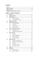
information vii About this guide vii M4N68T-M LE specifications summary ix Chapter 1: Product introduction 1.1 Welcome 1-1 1.2 Package contents 1-1 1.3 Special features 1-1 1.3.1 Product highlights 1-1 1.3.2 Innovative ASUS features 1-3 1.4 Before you proceed 1-5 1.5 Motherboard overview - Asus M4N68T-M LE | User Manual - Page 4
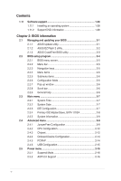
operating system 1-28 1.11.2 Support DVD information 1-28 Chapter 2: BIOS information 2.1 Managing and updating your BIOS 2-1 2.1.1 ASUS Update utility 2-1 2.1.2 ASUS EZ Flash 2 utility 2-2 2.1.3 ASUS CrashFree BIOS utility 2-3 2.2 BIOS setup program 2-4 2.2.1 BIOS menu screen 2-5 2.2.2 Menu - Asus M4N68T-M LE | User Manual - Page 5
Contents 2.5.3 ACPI APIC Support 2-16 2.5.4 APM Configuration 2-16 2.5.5 HW Monitor Configuration 2-17 2.6 Boot menu 2-18 2.6.1 Boot Device Priority 2-18 2.6.2 Boot Settings Configuration 2-18 2.6.3 Security 2-19 2.7 Tools menu 2-21 2.7.1 ASUS EZ Flash 2 2-21 2.7.2 Express Gate [Auto 2-21 - Asus M4N68T-M LE | User Manual - Page 6
accordance with manufacturer's instructions, may cause harmful the equipment off and on, the user is encouraged to try to correct the of the monitor to the graphics card is required to assure compliance ASUS REACH website at http://green.asus.com/english/REACH.htm. DO NOT throw the motherboard - Asus M4N68T-M LE | User Manual - Page 7
. • If you encounter technical problems with the product, contact a qualified service technician or your retailer. About this guide This user guide contains the information you need when installing and configuring the motherboard. How this guide is organized This guide contains the following parts - Asus M4N68T-M LE | User Manual - Page 8
guide To ensure that you perform certain tasks properly, take note of the following symbols used throughout this manual Instructions ASUS websites The ASUS website provides updated information on ASUS hardware and software products. Refer to the ASUS it�e�m�t�o�s�e�le�c�t. Italics - Asus M4N68T-M LE | User Manual - Page 9
LAN Audio USB Back panel I/O ports AMD® Socket AM3 for AMD® Phenom™ II / Athlon™ II / Sempron™ 100 series processors AMD® Cool 'n' Quiet™ Technology AMD 64 architecture enables simultaneous 32-bit and 64-bit computing * Refer to www.asus.com for the AMD® CPU support list GeForce 7025 / nForce 630a - Asus M4N68T-M LE | User Manual - Page 10
M4N68T-M LE specifications summary Internal I/O connectors BIOS ASUS special features ASUS overclocking features Accessories Support DVD Form factor 3 x USB 2.0/1.1 connectors support additional 6 USB 2.0/1.1 ports 4 x SATA connectors 1 x CPU fan connector 1 x Chassis fan connector 1 x High - Asus M4N68T-M LE | User Manual - Page 11
shield ASUS motherboard Support DVD User Manual If any of the above items is damaged or missing, contact your retailer. 1.3 1.3.1 Special features Product highlights AMD® Phenom™ II / Athlon™ II / Sempron™ 100 series CPU support This motherboard supports AMD® Socket AM3 multi-core processors with - Asus M4N68T-M LE | User Manual - Page 12
operating environment. Dual-Channel DDR3 1800 (O.C.) support This motherboard supports DDR3 memory that features data transfer rates of 1800 (O.C.)/1600 (O.C.)/1333/1066 MHz to meet the higher bandwidth requirements of the latest operating system, 3D graphics, multimedia, and Internet applications - Asus M4N68T-M LE | User Manual - Page 13
the BIOS file. ASUS EZ Flash 2 ASUS EZ Flash 2 allows you to update the BIOS from a USB flash disk before entering the OS. ASUS Q-Fan ASUS Q-Fan technology intelligently adjusts the CPU fan speed according to system loading to ensure a quiet, cool, and efficient operation. ASUS M4N68T-M LE 1-3 - Asus M4N68T-M LE | User Manual - Page 14
the system chassis and clear the RTC data. Simply shut down and reboot the system, and the BIOS automatically restores the CPU parameters to their default settings. Green ASUS This motherboard and its packaging comply with the European Union's Restriction on the use of Hazardous Substances (RoHS - Asus M4N68T-M LE | User Manual - Page 15
install motherboard components or change any motherboard settings. • Unplug the power cord from the wall socket motherboard component. The illustration below shows the location of the onboard LED. SB_PWR M4N68T-M LE ON OFF Standby Power Powered Off M4N68T-M LE Onboard LED ASUS M4N68T-M LE - Asus M4N68T-M LE | User Manual - Page 16
the image below. 1.5.2 Screw holes Place six screws into the holes indicated by circles to secure the motherboard to the chassis. DO NOT overtighten the screws! Doing so can damage the motherboard. Place this side towards the rear of the chassis. M4N68T-M LE 1-6 Chapter 1: Product introduction - Asus M4N68T-M LE | User Manual - Page 17
(10-1 pin F_PANEL) 1-25 5. AMD CPU socket 1-8 13. Onboard LED 1-5 6. DDR3 DIMM sockets 1-11 14. Digital audio connector (4-1 pin SPDIF_OUT) 1-27 7. IDE connector (40-1 pin PRI_IDE) 1-23 15. Front panel audio connector (10-1 pin AAFP) 1-21 8. Clear RTC RAM (CLRTC) 1-18 ASUS M4N68T-M LE 1-7 - Asus M4N68T-M LE | User Manual - Page 18
supports AMD® Phenom™ II / Athlon™ II / Sempron™ 100 series processors. The AM3 socket has a different pinout from the the AM2+/AM2 socket. Ensure that you use a CPU designed for the AM3 socket. 1.6.1 Installing the CPU To install a CPU: 1. Locate the CPU socket on the motherboard. M4N68T-M LE - Asus M4N68T-M LE | User Manual - Page 19
. You can also refer to section 1.6.2 Installing heatsink and fan for instructions. 7. Connect the CPU fan cable to the CPU_FAN connector on the motherboard. M4N68T-M LE CPU_FAN CPU FAN PWM CPU FAN IN CPU FAN PWR GND M4N68T-M LE CPU fan connector DO NOT forget to connect the CPU fan connector - Asus M4N68T-M LE | User Manual - Page 20
that you use only AMD-certified heatsink and fan assembly. To install the CPU heatsink and fan: 1. Place the heatsink on top of the installed CPU, ensuring that the heatsink fits properly on the retention module base. • The retention module base is already installed on the motherboard upon purchase - Asus M4N68T-M LE | User Manual - Page 21
motherboard comes with two Double Data Rate 3 (DDR3) Dual Inline Memory Modules (DIMM) sockets. The figure illustrates the location of the DDR3 DIMM sockets: DIMM_A1 DIMM_B1 M4N68T-M LE Channel Channel A Channel B M4N68T-M LE 240-pin DDR3 DIMM sockets Sockets DIMM_A1 DIMM_B1 ASUS M4N68T-M LE - Asus M4N68T-M LE | User Manual - Page 22
DDR3 DIMMs into the DIMM sockets optimum compatibility, we motherboard. • This motherboard does not support DIMMs made up of 256 megabits (Mb) chips or less. M4N68T-M LE Motherboard Qualified Vendors Lists (QVL) DDR3 Brand Chip NO. Timing DIMM (BIOS) Voltage DIMM Support A* B* DS N/A Heat-Sink - Asus M4N68T-M LE | User Manual - Page 23
Package 9 •• DDR3-1333 MHz capability BIOS) 8-8-8-24 8-8-8-24 9 9 9-9-9-24 9-9-9-24 9 9-9-9-24 9 9 6-6-6-20 9 9 9 6-6-6-20 6-6-6-20 7-7-7-24 Voltage 1.651.85V 1.651.85V 1.60V 1.50V 1.5V 1.50V 1.8V 1.8V 1.8V 1.65V DIMM Support A* B 9 • (continued on the next page) ASUS M4N68T-M LE - Asus M4N68T-M LE | User Manual - Page 24
-6GBPK F3-10666CL9T-6GBNQ DDR3-1333 CL9-9-9-24 GV34GB1333C7DC GG34GB1333C9DC GEIL DDR3-1333 CL9-9-9-24 Kingmax N/A K4B1G0846D(ECC) 2048MB DS Micron 9GF27D9KPT 2048MB DS N/A SEC816HCH9K4B1G0846D Timing DIMM (BIOS) Voltage DIMM Support A* B* • •• 7-7-7-18 1.5~1.6V • • 9-9-9-24 1.5~1.6V • - Asus M4N68T-M LE | User Manual - Page 25
Supports one module inserted into either slot as single-channel memory configuration. • B*: Supports one pair of modules inserted into both the blue slots as one pair of dual-channel memory configuration. Visit the ASUS website at www.asus.com for the latest QVL. ASUS M4N68T-M LE 1-15 - Asus M4N68T-M LE | User Manual - Page 26
before adding or removing DIMMs or other system components. Failure to do so can cause severe damage to both the motherboard and the components. 1. Press the retaining clips outward to unlock a DIMM socket. 2. Align a DIMM on the socket such that the notch on the DIMM matches the break on the - Asus M4N68T-M LE | User Manual - Page 27
x1 slot This motherboard supports PCI Express x1 network cards, SCSI cards, and other cards that comply with the PCI Express specifications. 1.8.5 PCI Express x16 slot This motherboard supports a PCI Express x16 graphics card that comply with the PCI Express specifications. ASUS M4N68T-M LE 1-17 - Asus M4N68T-M LE | User Manual - Page 28
information such as system passwords. CLRTC 12 23 M4N68T-M LE Normal (Default) Clear RTC M4N68T-M LE Clear RTC RAM To erase the RTC RAM: ON the computer. 4. Hold down the key during the boot process and enter BIOS setup to reenter data. Except when clearing the RTC RAM, never remove - Asus M4N68T-M LE | User Manual - Page 29
the Space Bar). This feature requires an ATX power supply that can supply at least 1A on the +5VSB lead, and a corresponding setting in the BIOS. KBPWR 12 23 +5V +5VSB (Default) M4N68T-M LE M4N68T-M LE Keyboard Power Setting ASUS M4N68T-M LE 1-19 - Asus M4N68T-M LE | User Manual - Page 30
. This port allows Gigabit connection to a Local Area Network (LAN) through a network hub. LAN port LED indications Activity/Link LED Status Description Out To configure 8-channel audio, use the chassis with HD audio module in the front panel to support 8-channel audio output. 1-20 Chapter - Asus M4N68T-M LE | User Manual - Page 31
-definition audio capability. • If you want to connect a high definition front panel audio module to this connector, set the Front Panel Select item in the BIOS to [HD Audio]. See section 2.4.3 Chipset for details. • The front panel audio I/O module is purchased separately. ASUS M4N68T-M LE 1-21 - Asus M4N68T-M LE | User Manual - Page 32
completely fit. ATX12V EATXPWR +12V DC +12V DC M4N68T-M LE GND GND +3 Volts +12 Volts +12 Volts +5V The system may become unstable or may not boot up if the power is inadequate. • If Wattage Calculator at http://support.asus. com/PowerSupplyCalculator/PSCalculator.aspx?SLanguage - Asus M4N68T-M LE | User Manual - Page 33
cable: blue, black, and gray. Connect the blue connector to the motherboard's IDE connector, then select one of the following modes to configure your setting. PRI_IDE M4N68T-M LE PIN1 NOTE:Orient the red markings on the IDE ribbon cable to PIN 1. M4N68T-M LE IDE connector ASUS M4N68T-M LE 1-23 - Asus M4N68T-M LE | User Manual - Page 34
Guide included in the folder named Manual in the support DVD. 5. Internal speaker connector (4-pin SPEAKER) The 4-pin connector is for the chassis-mounted system warning speaker. The speaker allows you to hear system beeps and warnings. SPEAKER +5V GND GND Speaker Out M4N68T-M LE PIN 1 M4N68T - Asus M4N68T-M LE | User Manual - Page 35
panel connector (10-1 pin F_PANEL) This connector supports several chassis-mounted functions. PWR LED PWR BTN F_PANEL PIN 1 M4N68T-M LE HD_LED RESET M4N68T-M LE System panel connector • System power LED (2- reset button for system reboot without turning off the system power. ASUS M4N68T-M LE 1-25 - Asus M4N68T-M LE | User Manual - Page 36
+ GND NC USB+5V USB_P7USB_P7+ GND USB+5V USB_P9USB_P9+ GND M4N68T-M LE PIN 1 PIN 1 PIN 1 USB+5V USB_P5USB_P5+ GND M4N68T-M LE USB2.0 connectors Never connect a 1394 cable to the USB connectors. Doing so will damage the motherboard! The USB 2.0 module is purchased separately. 1-26 Chapter - Asus M4N68T-M LE | User Manual - Page 37
NOT forget to connect the fan cables to the fan connectors. Insufficient air flow inside the system may damage the motherboard components. These are not jumpers! DO NOT place jumper caps on the fan connectors. Only the 4-pin CPU fan connector supports the ASUS Q-Fan feature. ASUS M4N68T-M LE 1-27 - Asus M4N68T-M LE | User Manual - Page 38
or later versions / Windows® Vista Service Pack 1 or later versions before installing the drivers for better compatibility and system stability. 1.11.2 Support DVD information The Support DVD that comes with the motherboard package contains the drivers, software applications, and utilities that you - Asus M4N68T-M LE | User Manual - Page 39
connection either through a network or an Internet Service Provider (ISP). • This utility is available in the support DVD that comes with the motherboard package. Installing ASUS Update To install ASUS Update: 1. Place the support DVD into the optical drive. The Drivers menu appears. 2. Click - Asus M4N68T-M LE | User Manual - Page 40
file is found, then press . EZ Flash 2 performs the BIOS updating process and automatically reboots the system when done. ASUSTek EZ Flash 2 BIOS ROM Utility V3.44 FLASH TYPE: WINBOND W25X80 Current ROM BOARD: M4N68T-M LE VER: 0301 (H:00 B:00) DATE: 11/27/2009 Update ROM BOARD: Unknown - Asus M4N68T-M LE | User Manual - Page 41
down or reset the system while updating the BIOS! Doing so can cause system boot failure! Ensure to load the BIOS default settings to ensure system compatibility and stability. Select the Load Setup Defaults item under the Exit menu. Refer to section 2.8 Exit menu for details. ASUS M4N68T-M LE 2-3 - Asus M4N68T-M LE | User Manual - Page 42
from the operating system. • The default BIOS settings for this motherboard apply to most conditions to ensure optimum performance. If the system becomes unstable after changing any BIOS settings, load the default settings to ensure system compatibility and stability. Select the Load Setup Defaults - Asus M4N68T-M LE | User Manual - Page 43
menu screen Menu items Menu bar Configuration fields Main Advanced Power BIOS SETUP UTILITY Boot Tools Exit Main Settings System Time [19:34:30] System Date [Fri 11/13/2009] and change the settings. Some of the navigation keys differ from one screen to another. ASUS M4N68T-M LE 2-5 - Asus M4N68T-M LE | User Manual - Page 44
field opposite the item. You cannot select an item that is not user-configurable. A configurable field is enclosed in brackets, and is highlighted screen. Main Advanced BIOS SETUP UTILITY Power Boot Tools Exit Suspend Mode ACPI 2.0 Support ACPI APIC support APM Configuration Hardware - Asus M4N68T-M LE | User Manual - Page 45
and how to navigate through them. Main Advanced Main Settings Power BIOS SETUP UTILITY Boot Tools Exit System Time [19:34:30] System Date [Fri nVidia RAID Function [Disabled] Enables or disables the nVidia RAID function. Configuration options: [Disabled] [Enabled] ASUS M4N68T-M LE 2-7 - Asus M4N68T-M LE | User Manual - Page 46
display the IDE/SATA device information. The BIOS automatically detects the values opposite the dimmed items DMA, and SMART monitoring). These values are not user-configurable. These items show Not Detected if no sectors at a time if the device supports multisector transfer feature. When this item is - Asus M4N68T-M LE | User Manual - Page 47
The items and configuration options in this menu may vary depending on the AMD CPU type. CPU OverClocking [Auto] Selects the CPU overclocking options to achieve desired CPU internal frequency. Configuration options: [Manual] [Auto] [Standard] [Overclock Profile] ASUS M4N68T-M LE 2-9 - Asus M4N68T-M LE | User Manual - Page 48
[Auto] [Overclock 3%] [Overclock 5%] [Overclock 7%] PCIE Overclocking [Auto] Configures the PCIE overclocking. Configuration options: [Auto] [Manual] The following item only appears when you set PCIE Overclocking to [Manual]. PCIE Frequency [100] Sets the PCIE Clock. Configuration options: [Min.=100 - Asus M4N68T-M LE | User Manual - Page 49
memory clock mode. Configuration options: [Auto] [Manual] The following item only appears when you set Memory Clock Mode to [Manual]. Memclock Value [400MHz] Selects the DRAM frequency keys to adjust the value. Configuration options: [Auto] [Max. = 1.60000V] [Min. = 1.20000V] ASUS M4N68T-M LE 2-11 - Asus M4N68T-M LE | User Manual - Page 50
information that the BIOS automatically detects. GART Error Reporting [Disabled] This option should remain disabled for the normal operation. The driver developer may [Enabled] Cool 'n' Quiet [Enabled] Enables or disables the AMD® Cool 'n' Quiet technology. Configuration options: [Enabled] [Disabled - Asus M4N68T-M LE | User Manual - Page 51
options: [HD Audio] [AC97] MAC LAN [Disabled] Enables or disables the onboard LAN controller. Configuration options: [Enabled] [Disabled] OnBoard LAN Boot ROM [Disabled] This item appears only when the MAC LAN item is set to [Auto]. Configuration options: [Disabled] [Enabled] ASUS M4N68T-M LE 2-13 - Asus M4N68T-M LE | User Manual - Page 52
the PCI PnP menu items. Incorrect field values can cause the system to malfunction. Plug and Play O/S [No] When this item is set to [No], BIOS configures all the devices in the system. When this item is set to [Yes] and if you install a Plug and Play operating system, the operating - Asus M4N68T-M LE | User Manual - Page 53
the legacy USB support is disabled. BIOS waits for the USB storage device to initialize. Configuration options: [10 Sec] [20 Sec] [30 Sec] [40 Sec] Emulation Type [Auto] Allows you to set the emulation type. Configuration options: [Auto] [Floppy] [Forced FDD] [Hard Disk] [CDROM] ASUS M4N68T-M LE - Asus M4N68T-M LE | User Manual - Page 54
BIOS SETUP UTILITY Boot Tools Exit Power Settings Suspend Mode [Auto] ACPI 2.0 Support [Enabled] ACPI APIC Support a PCI Express/ PCI card. This feature requires an ATX power supply that provides ra��ti�o�n��o�p��ti�o�n�s��: �[D��i�s�a�b�l�e�d�]��[E��n�a�b��le��d�] Power on By Ring - Asus M4N68T-M LE | User Manual - Page 55
in rotations per minute (RPM). If the fan is not connected to the motherboard, the field shows N/A. Select [gnored] if you do not want the ASUS Q-Fan feature that smartly adjusts the CPU fan speeds for more efficient system operation. Configuration options: [Disabled] [Enabled] ASUS M4N68T-M LE - Asus M4N68T-M LE | User Manual - Page 56
of the following: • Press when ASUS logo appears. • Press after POST. 2.6.2 Boot Settings Configuration Quick Boot [Enabled] Enabling this item allows the BIOS to skip some power on self tests (POST) while booting to decrease the time needed to boot the system. When this item is set - Asus M4N68T-M LE | User Manual - Page 57
, select the Change Supervisor Password then press twice. The message Password uninstalled appears. If you forget your BIOS password, you can clear it by erasing the CMOS Real Time Clock (RTC) RAM. See section 1.9 Jumpers for information on how to erase the RTC RAM. ASUS M4N68T-M LE 2-19 - Asus M4N68T-M LE | User Manual - Page 58
Select this item to clear the user password. Password Check [Setup] When set to [Setup], BIOS checks for user password when accessing the Setup utility. When set to [Always], BIOS checks for user password both when accessing Setup and booting the system. Configuration options: [Setup] [Always - Asus M4N68T-M LE | User Manual - Page 59
Advanced Power BIOS SETUP UTILITY Boot Tools Exit ASUS EZ Flash 2 Express Gate Enter OS Timer Reset User Data [Auto] [10 Seconds] [No] Press ENTER to run the utility to select and update BIOS. This utility supports: 1. Express Gate environment after clearing its settings. ASUS M4N68T-M LE 2-21 - Asus M4N68T-M LE | User Manual - Page 60
Current CMOS BOARD: M4N68T-M LE VER: 0301 (H:00 B:00) DATE: 11/27/2009 Restore CMOS BOARD: Unknown VER: Unknown DATE: Unknown PATH: C:\ C: Note [Enter] Select or Load [Tab] Switch [Up/Down/Home/End] Move [B] Backup [V] Drive Info [ESC] Exit • This function can support devices such as a USB - Asus M4N68T-M LE | User Manual - Page 61
the optimal or failsafe default values for the BIOS items, and save or discard your changes to the BIOS items. Main Advanced Power BIOS SETUP UTILITY Boot Tools Exit Exit Options Exit & Save Changes Exit make other changes before saving the values to the non-volatile RAM. ASUS M4N68T-M LE 2-23 - Asus M4N68T-M LE | User Manual - Page 62
2-24 Chapter 2: BIOS information
-
 1
1 -
 2
2 -
 3
3 -
 4
4 -
 5
5 -
 6
6 -
 7
7 -
8
-
9
-
10
-
11
-
12
-
13
-
14
-
15
-
16
-
17
-
18
-
19
-
20
-
21
-
22
-
23
-
24
-
25
-
26
-
27
-
28
-
29
-
30
-
31
-
32
-
33
-
34
-
35
-
36
-
37
-
38
-
39
-
40
-
41
-
42
-
43
-
44
-
45
-
46
-
47
-
48
-
49
-
50
-
51
-
52
-
53
-
54
-
55
-
56
-
57
-
58
-
59
-
60
-
61
-
62
 |
 |

Motherboard
M4N68T-M LE