Asus M4N68T-M User Manual
Asus M4N68T-M Manual
 |
View all Asus M4N68T-M manuals
Add to My Manuals
Save this manual to your list of manuals |
Asus M4N68T-M manual content summary:
- Asus M4N68T-M | User Manual - Page 1
M4N68T-M Motherboard - Asus M4N68T-M | User Manual - Page 2
of three years after our last shipment of the product including the GPL Software and/or LGPL Software, which will be no earlier than December 1, 2011, either (1) for free by downloading it from http://support.asus.com/download; or (2) for the cost of reproduction and shipment, which is dependent on - Asus M4N68T-M | User Manual - Page 3
vii About this guide vii M4N68T-M specifications summary ix Chapter: Product introduction 1.1 Welcome 1-1 1.2 Package contents 1-1 1.3 Special features 1-1 1.3.1 Product highlights 1-1 1.3.2 Innovative ASUS features 1-3 1.4 Before you proceed 1-5 1.5 Motherboard overview 1-6 1.5.1 Placement - Asus M4N68T-M | User Manual - Page 4
1.11 Software support 1-28 1.11.1 Installing an operating system 1-28 1.11.2 Support DVD information 1-28 Chapter: BIOS information 2.1 Managing and updating your BIOS 2-1 2.1.1 ASUS Update utility 2-1 2.1.2 ASUS EZ Flash 2 utility 2-2 2.1.3 ASUS CrashFree BIOS utility 2-3 2.2 BIOS setup - Asus M4N68T-M | User Manual - Page 5
HW Monitor Configuration 2-17 2.5.6 Anti Surge Support 2-17 2.6 Boot menu 2-18 2.6.1 Boot Device Priority 2-18 2.6.2 Boot Settings Configuration 2-18 2.6.3 Security 2-19 2.7 Tools menu 2-21 2.7.1 ASUS EZ Flash 2 2-21 2.7.2 Express Gate 2-21 2.7.3 ASUS O.C. Profile 2-22 2.7.4 AI NET 2 2-22 - Asus M4N68T-M | User Manual - Page 6
and used in accordance with manufacturer's instructions, may cause harmful interference to radio for connection of the monitor to the graphics card is required to assure compliance with FCC regulations at ASUS REACH website at http://green.asus.com/english/REACH.htm. DO NOT throw the motherboard in - Asus M4N68T-M | User Manual - Page 7
. • If you encounter technical problems with the product, contact a qualified service technician or your retailer. About this guide This user guide contains the information you need when installing and configuring the motherboard. How this guide is organized This guide contains the following parts - Asus M4N68T-M | User Manual - Page 8
guide To ensure that you perform certain tasks properly, take note of the following symbols used throughout this manual Instructions software updates. 1. ASUS websites The ASUS website provides updated information on ASUS hardware and software products. Refer to the ASUS it�e�m�t�o�s�e�le�c�t. - Asus M4N68T-M | User Manual - Page 9
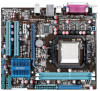
LAN Audio USB Back panel I/O ports AMD® Socket AM3 for AMD® Phenom™ II / Athlon™ II / Sempron™ 100 series processors AMD® Cool 'n' Quiet™ Technology AMD 64 architecture enables simultaneous 32-bit and 64-bit computing * Refer to www.asus.com for the AMD® CPU support list GeForce 7025 / nForce 630a - Asus M4N68T-M | User Manual - Page 10
at 1MHz increment ASUS C.P.R. (CPU Parameter Recall) 2 x Serial ATA cables 1 x Ultra DMA 133/100 cable 1 x I/O shield 1 x User Manual Drivers ASUS Update ASUS PC Probe II Anti-Virus software (OEM version) MicroATX form factor: 9.6 in x 8.2 in (24.4 cm x 20.8 cm) *Specifications are subject to - Asus M4N68T-M | User Manual - Page 11
Phenom™ II / Athlon™ II / Sempron™ 100 series CPU support This motherboard supports AMD® Socket AM3 multi-core processors with unique L3 cache and delivers better overclocking capabilities with less power consumption. It features dual-channel DDR3 memory support and accelerates data transfer rate up - Asus M4N68T-M | User Manual - Page 12
Quiet Technology This motherboard supports the AMD® Cool 'n' Quiet technology which monitors system operation and automatically adjusts CPU voltage and frequency for a cool and quiet operating environment. Dual-Channel DDR3 1800 (O.C.) support This motherboard supports DDR3 memory that features data - Asus M4N68T-M | User Manual - Page 13
the BIOS file. ASUS EZ Flash 2 ASUS EZ Flash 2 allows you to update the BIOS from a USB flash disk before entering the OS. ASUS Q-Fan ASUS Q-Fan technology intelligently adjusts the CPU fan speed according to system loading to ensure a quiet, cool, and efficient operation. ASUS M4N68T-M 1-3 - Asus M4N68T-M | User Manual - Page 14
the system hangs due to overclocking failure. C.P.R. eliminates the need to open the system chassis and clear the RTC data. Simply shut down and reboot the system, and the BIOS automatically restores the CPU parameters to their default settings. Green ASUS This motherboard and its packaging comply - Asus M4N68T-M | User Manual - Page 15
. This is a reminder that you should shut down the system and unplug the power cable before removing or plugging in any motherboard component. The illustration below shows the location of the onboard LED. M4N68T-M SB_PWR ON OFF Standby Power Powered Off M4N68T-M Onboard LED ASUS M4N68T-M 1-5 - Asus M4N68T-M | User Manual - Page 16
overview 1.5.1 Placement direction When installing the motherboard, ensure that you place it into the chassis in the correct orientation. Screw holes Place six screws into the holes indicated by circles to secure the motherboard to the chassis. DO NOT overtighten the screws! Doing so can damage the - Asus M4N68T-M | User Manual - Page 17
) DDR3 DIMM_B1 (64bit, 240-pin module) PRI_IDE SOCKET AM3 VGA LPT 7 USBPW1-4 USB34 24.4cm(9.6in) LAN1_USB12 Super I/O CPU_FAN EATXPWR AUDIO CHA_FAN Lithium Cell CMOS Power M4N68T-M PCIEX16 3 8Mb BIOS RTL 8211CL PCIEX1_1 PCI1 NVIDIA® MCP68 SE 8 CLRTC 2 SATA2 SATA4 PCI2 VIA - Asus M4N68T-M | User Manual - Page 18
supports AMD® Phenom™ II / Athlon™ II / Sempron™ 100 series processors. The AM3 socket has a different pinout from the the AM2+/AM2 socket. Ensure that you use a CPU designed for the AM3 socket. 1.6.1 Installing the CPU To install a CPU: 1. Locate the CPU socket on the motherboard. M4N68T-M M4N68T - Asus M4N68T-M | User Manual - Page 19
Connect the CPU fan cable to the CPU_FAN connector on the motherboard. M4N68T-M CPU_FAN CPU FAN PWM CPU FAN IN CPU FAN PWR GND M4N68T-M CPU fan connector DO NOT forget to connect the CPU fan connector! Hardware monitoring errors can occur if you fail to plug this connector. ASUS M4N68T-M 1-9 - Asus M4N68T-M | User Manual - Page 20
that you use only AMD-certified heatsink and fan assembly. To install the CPU heatsink and fan: 1. Place the heatsink on top of the installed CPU, ensuring that the heatsink fits properly on the retention module base. • The retention module base is already installed on the motherboard upon purchase - Asus M4N68T-M | User Manual - Page 21
The motherboard comes with two Double Data Rate 3 (DDR3) Dual Inline Memory Modules (DIMM) sockets. The figure illustrates the location of the DDR3 DIMM sockets: DIMM_A1 DIMM_B1 M4N68T-M Channel Channel A Channel B M4N68T-M 240-pin DDR3 DIMM sockets Sockets DIMM_A1 DIMM_B1 ASUS M4N68T-M 1-11 - Asus M4N68T-M | User Manual - Page 22
memory on the motherboard. • This motherboard does not support DIMMs made up of 256 megabits (Mb) chips or less. M4N68T-M Motherboard Qualified Vendors Lists (Kit of 3) SS/ DS Brand Chip NO. Timing DIMM (BIOS) Voltage DIMM Support A* B* DS N/A Heat-Sink Package 7-7-7-20 1.75-1.85V • - Asus M4N68T-M | User Manual - Page 23
Package Micron 8UD22D9JNM Timing DIMM (BIOS) 8-8-8-24 8-8-8-24 9 9 9-9-9-24 9-9-9-24 9 9-9-9-24 9 9 6-6-6-20 9 9 9 6-6-6-20 6-6-6-20 7-7-7-24 Voltage 1.651.85V 1.651.85V 1.60V 1.50V 1.5V 1.50V 1.8V 1.8V 1.8V 1.65V DIMM Support A* B 9 • (continued on the next page) ASUS M4N68T-M 1-13 - Asus M4N68T-M | User Manual - Page 24
1024MB SS N/A K4B1G0846D(ECC) 2048MB DS Micron 9GF27D9KPT 2048MB DS N/A SEC816HCH9K4B1G0846D Timing DIMM (BIOS) Voltage DIMM Support A* B* • •• 7-7-7-18 1.5~1.6V • • 9-9-9-24 1.5~1.6V • • •• • 8-8-8-21 1.5-1.6V • • 7-7-7-18 1.5~1.6V • • 9-9-9-24 1.5V~1.6V • • 9 •• 7-7-7-24 1.5V - Asus M4N68T-M | User Manual - Page 25
• A*: Supports one module inserted into either slot as single-channel memory configuration. • B*: Supports one pair of modules inserted into both the blue slots as one pair of dual-channel memory configuration. Visit the ASUS website at www.asus.com for the latest QVL. ASUS M4N68T-M 1-15 - Asus M4N68T-M | User Manual - Page 26
before adding or removing DIMMs or other system components. Failure to do so can cause severe damage to both the motherboard and the components. 1. Press the retaining clips outward to unlock a DIMM socket. 2. Align a DIMM on the socket such that the notch on the DIMM matches the break on the - Asus M4N68T-M | User Manual - Page 27
x1 slot This motherboard supports PCI Express x1 network cards, SCSI cards, and other cards that comply with the PCI Express specifications. 1.8.5 PCI Express x16 slot This motherboard supports a PCI Express x16 graphics card that comply with the PCI Express specifications. ASUS M4N68T-M 1-17 - Asus M4N68T-M | User Manual - Page 28
can clear the CMOS memory of date, time, . M4N68T-M CLRTC 12 23 Normal (Default) M4N68T-M key during the boot process and enter BIOS setup to reenter overclocking. For system failure due to overclocking, use the CPU Parameter Recall (C.P.R) feature. Shut down and reboot the system so the BIOS - Asus M4N68T-M | User Manual - Page 29
Set these jumpers to +5V to wake up the computer from S1 sleep mode (CPU stopped, DRAM refreshed, system running in low power mode) using the connected USB devices a corresponding setting in the BIOS. KBPWR 12 23 +5V +5VSB (Default) M4N68T-M M4N68T-M Keyboard Power Setting ASUS M4N68T-M 1-19 - Asus M4N68T-M | User Manual - Page 30
In - 6-channel Rear Speaker Out Front Speaker Out Bass/Center - 8-channel Rear Speaker Out Front Speaker Out Bass/Center Side Speaker Out To configure 8-channel audio, use the chassis with HD audio module in the front panel to support 8-channel audio output. 1-20 Chapter 1: Product introduction - Asus M4N68T-M | User Manual - Page 31
high-definition audio capability. • If you want to connect a high definition front panel audio module to this connector, set the Front Panel Select item in the BIOS to [HD Audio]. See section 2.4.3 Chipset for details. • The front panel audio I/O module is purchased separately. ASUS M4N68T-M 1-21 - Asus M4N68T-M | User Manual - Page 32
M4N68T-M ATX power connectors GND +5 Volts +5 Volts +5 Volts -5 Volts GND GND GND PSON# GND -12 Volts +3 Volts • We recommend that you use an ATX 12V Specification system may become unstable or may not boot up if the power is inadequate. at http://support.asus. com/PowerSupplyCalculator/PSCalculator - Asus M4N68T-M | User Manual - Page 33
signal cable: blue, black, and gray. Connect the blue connector to the motherboard's IDE connector, then select one of the following modes to configure your same setting. PRI_IDE M4N68T-M PIN1 NOTE:Orient the red markings on the IDE ribbon cable to PIN 1. M4N68T-M IDE connector ASUS M4N68T-M 1-23 - Asus M4N68T-M | User Manual - Page 34
hard disk drive that includes a RAID/AHCI set. • Due to Windows® XP limitation, Windows® XP may not recognize the USB floppy disk drive. • For more details on RAID/AHCI, refer to the RA ID/AHCI Supplementary Guide included in the folder named Manual in the support DVD. 5. Internal speaker connector - Asus M4N68T-M | User Manual - Page 35
pin F_PANEL) This connector supports several chassis-mounted functions. PWR LED PWR BTN PLED+ PLEDPWR GND IDE_LED+ IDE_LED- Ground Reset M4N68T-M F_PANEL PIN 1 HD_LED RESET M4N68T-M System panel connector • reset button for system reboot without turning off the system power. ASUS M4N68T-M 1-25 - Asus M4N68T-M | User Manual - Page 36
chassis. These USB connectors comply with USB 2.0 specification that supports up to 480Mbps connection speed. USB+5V USB_P8USB_P8 M4N68T-M PIN 1 PIN 1 PIN 1 USB+5V USB_P5USB_P5+ GND M4N68T-M USB2.0 connectors Never connect a 1394 cable to the USB connectors. Doing so will damage the motherboard - Asus M4N68T-M | User Manual - Page 37
DO NOT forget to connect the fan cables to the fan connectors. Insufficient air flow inside the system may damage the motherboard components. These are not jumpers! DO NOT place jumper caps on the fan connectors. Only the 4-pin CPU fan connector supports the ASUS Q-Fan feature. ASUS M4N68T-M 1-27 - Asus M4N68T-M | User Manual - Page 38
install Windows® XP Service Pack 3 or later versions / Windows® Vista Service Pack 1 or later versions before installing the drivers for better compatibility and system stability. 1.11.2 Support DVD information The Support DVD that comes with the motherboard package contains the drivers, software - Asus M4N68T-M | User Manual - Page 39
with the motherboard package. Installing ASUS Update To install ASUS Update: 1. Place the support DVD into the optical drive. The Drivers menu appears. 2. Click the Utilities tab, then click ASUS Update. 3. Follow the onscreen instructions to complete the installation. Quit all Windows® applications - Asus M4N68T-M | User Manual - Page 40
the Open window, then click Open. 3. Follow the onscreen instructions to complete the updating process. 2.1.2 ASUS EZ Flash 2 utility The ASUS EZ Flash 2 feature allows you to update the BIOS without using an OS‑based utility. Before you start using this utility, download the latest BIOS file from - Asus M4N68T-M | User Manual - Page 41
down or reset the system while updating the BIOS! Doing so can cause system boot failure! Ensure to load the BIOS default settings to ensure system compatibility and stability. Select the Load Setup Defaults item under the Exit menu. Refer to section 2.8 Exit menu for details. ASUS M4N68T-M 2-3 - Asus M4N68T-M | User Manual - Page 42
system compatibility and stability. Select the Load Setup Defaults item under the Exit menu. See section 2.8 Exit Menu. • The BIOS setup screens in this chapter are for reference only. They may not exactly match what you see on your screen. • Visit the ASUS website at www.asus.com to download the - Asus M4N68T-M | User Manual - Page 43
item is highlighted. 2.2.3 Navigation keys At the bottom right corner of a menu screen are the navigation keys for that particular menu. Use the navigation keys to select items in the menu and change the settings. Some of the navigation keys differ from one screen to another. ASUS M4N68T-M 2-5 - Asus M4N68T-M | User Manual - Page 44
side of a menu screen when there are items that do not fit on the screen. Press the / arrow keys or / keys to display the other items on the screen. Main Advanced BIOS SETUP UTILITY Power Boot Tools Exit Suspend Mode ACPI 2.0 Support ACPI APIC support APM - Asus M4N68T-M | User Manual - Page 45
BIOS menu screen for information on the menu screen items and how to navigate through them. Main Advanced Main Settings Power BIOS SETUP UTILITY Boot Tools nVidia RAID Function [Disabled] Enables or disables the nVidia RAID function. Configuration options: [Disabled] [Enabled] ASUS M4N68T-M - Asus M4N68T-M | User Manual - Page 46
display the IDE/SATA device information. The BIOS automatically detects the values opposite the dimmed items device type. Select [CDROM] if you are specifically configuring a CD-ROM drive. Select [ARMD] multiple sectors at a time if the device supports multisector transfer feature. When this item is - Asus M4N68T-M | User Manual - Page 47
Configuration The items and configuration options in this menu may vary depending on the AMD CPU type. CPU OverClocking [Auto] Selects the CPU overclocking options to achieve desired CPU internal frequency. Configuration options: [Manual] [Auto] [Standard] [Overclock Profile] ASUS M4N68T-M 2-9 - Asus M4N68T-M | User Manual - Page 48
[Overclock 3%] [Overclock 5%] [Overclock 7%] PCIE Overclocking [Auto] Configures the PCIE overclocking. Configuration options: [Auto] [Manual] The following item only appears when you set PCIE Overclocking to [Manual]. PCIE Frequency [100] Sets the PCIE Clock. Configuration options: [Min.=100] [Max - Asus M4N68T-M | User Manual - Page 49
[Auto] [Max. = 2.4450V] [Min. = 1.5000V] Chipset Over Voltage [Auto] Sets the chipset over voltage. The values range from 1.20000V to 1.60000V with a 0.01000V increment. Use the / keys to adjust the value. Configuration options: [Auto] [Max. = 1.60000V] [Min. = 1.20000V] ASUS M4N68T-M 2-11 - Asus M4N68T-M | User Manual - Page 50
this menu show the CPU-related information that the BIOS automatically detects. GART Error Reporting [Disabled] This option should remain disabled for the normal operation. The driver developer may enable it for testing purpose. Configuration options: [Disabled] [Enabled] Microcode Updation [Enabled - Asus M4N68T-M | User Manual - Page 51
options: [HD Audio] [AC97] MAC LAN [Disabled] Enables or disables the onboard LAN controller. Configuration options: [Enabled] [Disabled] OnBoard LAN Boot ROM [Disabled] This item appears only when the MAC LAN item is set to [Auto]. Configuration options: [Disabled] [Enabled] ASUS M4N68T-M 2-13 - Asus M4N68T-M | User Manual - Page 52
setting IRQ and DMA channel resources for either PCI/PnP or legacy ISA devices, and setting the memory size block for legacy ISA devices. Take caution when changing the settings of the PCI PnP menu items. Incorrect field values can cause the system to malfunction. Plug and Play O/S [No] When this - Asus M4N68T-M | User Manual - Page 53
menu the legacy USB support is disabled. BIOS waits for the USB storage device to initialize. Configuration options: [10 Sec] [20 Sec] [30 Sec] [40 Sec] Emulation Type [Auto] Allows you to set the emulation type. Configuration options: [Auto] [Floppy] [Forced FDD] [Hard Disk] [CDROM] ASUS M4N68T - Asus M4N68T-M | User Manual - Page 54
Advanced Power BIOS SETUP UTILITY Boot Tools Exit Power Settings Suspend Mode [Auto] ACPI 2.0 Support [Enabled] ACPI APIC Support [Enabled] support in the Advanced Programmable Interrupt Controller (APIC). When set to Enabled, the ACPI APIC table pointer is included in the RSDT pointer list - Asus M4N68T-M | User Manual - Page 55
or disables the ASUS Q-Fan feature that smartly adjusts the CPU fan speeds for more efficient system operation. Configuration options: [Disabled] [Enabled] 2.5.6 Anti Surge Support [Enabled] Enables or disables the Anti-Surge function. Configuration options: [Disabled] [Enabled] ASUS M4N68T-M 2-17 - Asus M4N68T-M | User Manual - Page 56
system startup, press when ASUS logo appears. • To access Windows OS in Safe Mode, do any of the following: • Press when ASUS logo appears. • Press after POST. 2.6.2 Boot Settings Configuration Quick Boot [Enabled] Enabling this item allows the BIOS to skip some power on self - Asus M4N68T-M | User Manual - Page 57
Configuration options: [Disabled] [Enabled] 2.6.3 Security The Security menu items allow you to change the system security settings. Select BIOS password, you can clear it by erasing the CMOS Real Time Clock (RTC) RAM. See section 1.9 Jumpers for information on how to erase the RTC RAM. ASUS M4N68T - Asus M4N68T-M | User Manual - Page 58
item to clear the user password. Password Check [Setup] When set to [Setup], BIOS checks for user password when accessing the Setup utility. When set to [Always], BIOS checks for user password both when accessing Setup and booting the system. Configuration options: [Setup] [Always] 2-20 Chapter - Asus M4N68T-M | User Manual - Page 59
menu. Main Advanced Power BIOS SETUP UTILITY Boot Tools Exit ASUS EZ Flash 2 Express Gate Enter OS Timer Reset User Data [Auto] [10 Seconds] [No] Press ENTER to run the utility to select and update BIOS. This utility supports Gate environment after clearing its settings. ASUS M4N68T-M 2-21 - Asus M4N68T-M | User Manual - Page 60
down or reset the system while updating the BIOS to prevent the system boot failure! • We recommend that you update the BIOS file only coming from the same memory/CPU configuration and BIOS version. • Only the CMO file can be loaded. 2.7.4 AI NET 2 Check Realtek Phy LAN cable [Disabled] Enables or - Asus M4N68T-M | User Manual - Page 61
menu The Exit menu items allow you to load the optimal or failsafe default values for the BIOS items, and save or discard your changes to the BIOS items. Main Advanced Power BIOS SETUP UTILITY Boot Exit menu to a confirmation window appears. Select the BIOS asks confirmation window appears. Select - Asus M4N68T-M | User Manual - Page 62
2-24 Chapter 2: BIOS information
-
 1
1 -
 2
2 -
 3
3 -
 4
4 -
 5
5 -
 6
6 -
 7
7 -
8
-
9
-
10
-
11
-
12
-
13
-
14
-
15
-
16
-
17
-
18
-
19
-
20
-
21
-
22
-
23
-
24
-
25
-
26
-
27
-
28
-
29
-
30
-
31
-
32
-
33
-
34
-
35
-
36
-
37
-
38
-
39
-
40
-
41
-
42
-
43
-
44
-
45
-
46
-
47
-
48
-
49
-
50
-
51
-
52
-
53
-
54
-
55
-
56
-
57
-
58
-
59
-
60
-
61
-
62
 |
 |

Motherboard
M4N68T-M