Asus M4N68T-MV2 User Manual
Asus M4N68T-MV2 Manual
 |
View all Asus M4N68T-MV2 manuals
Add to My Manuals
Save this manual to your list of manuals |
Asus M4N68T-MV2 manual content summary:
- Asus M4N68T-MV2 | User Manual - Page 1
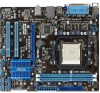
Motherboard M4N68T-M V2/ M4N68T-M LE V2 - Asus M4N68T-MV2 | User Manual - Page 2
that uses the Library") for a period of three years after our last shipment of the product including the GPL Software and/or LGPL Software, which will be no earlier than December 1, 2011, either (1) for free by downloading it from http://support.asus.com/download; or (2) for the cost of reproduction - Asus M4N68T-MV2 | User Manual - Page 3
vii About this guide vii M4N68T-M Series specifications summary ix Chapter 1: Product introduction 1.1 Welcome 1-1 1.2 Package contents 1-1 1.3 Special features 1-1 1.3.1 Product highlights 1-1 1.3.2 Innovative ASUS features 1-3 1.4 Before you proceed 1-5 1.5 Motherboard overview - Asus M4N68T-MV2 | User Manual - Page 4
system 1-28 1.11.2 Support DVD information 1-28 Chapter 2: BIOS information 2.1 Managing and updating your BIOS 2-1 2.1.1 ASUS Update utility 2-1 2.1.2 ASUS EZ Flash 2 utility 2-2 2.1.3 ASUS CrashFree BIOS utility 2-3 2.2 BIOS setup program 2-4 2.2.1 BIOS menu screen 2-5 2.2.3 Navigation - Asus M4N68T-MV2 | User Manual - Page 5
2-16 2.5.5 Hardware Monitor 2-17 2.5.6 Anti Surge Support [Enabled 2-18 2.6 Boot menu 2-19 2.6.1 Boot Device Priority 2-19 2.6.2 Boot Settings Configuration 2-19 2.6.3 Security 2-20 2.7 Tools menu 2-22 2.7.1 ASUS EZ Flash 2 2-22 2.7.2 ASUS O.C. Profile 2-22 2.7.3 AI NET 2 2-23 2.8 Exit - Asus M4N68T-MV2 | User Manual - Page 6
and used in accordance with manufacturer's instructions, may cause harmful interference to radio for connection of the monitor to the graphics card is required to assure compliance with FCC regulations at ASUS REACH website at http://csr.asus.com/english/REACH.htm. DO NOT throw the motherboard in - Asus M4N68T-MV2 | User Manual - Page 7
. • If you encounter technical problems with the product, contact a qualified service technician or your retailer. About this guide This user guide contains the information you need when installing and configuring the motherboard. How this guide is organized This guide contains the following parts - Asus M4N68T-MV2 | User Manual - Page 8
guide To ensure that you perform certain tasks properly, take note of the following symbols used throughout this manual Instructions updates. 1. ASUS websites The ASUS website provides updated information on ASUS hardware and software products. Refer to the ASUS it�e�m�t�o�s�e�le�c�t. Italics - Asus M4N68T-MV2 | User Manual - Page 9
RAID LAN Audio USB Back panel I/O ports AMD® Socket AM3 for AMD® Phenom™ II / Athlon™ II / Sempron™ 100 series processors AMD® Cool 'n' Quiet™ Technology AMD 64 architecture enables simultaneous 32-bit and 64-bit computing * Refer to www.asus.com for the AMD® CPU support list GeForce 7025 / nForce - Asus M4N68T-MV2 | User Manual - Page 10
M4N68T-M specifications summary Internal I/O connectors 3 x USB 2.0/1.1 connectors support additional 6 USB 2.0/1.1 ports 4 x SATA connectors 1 x CPU fan connector 1 x Chassis fan connector 1 x High definition front panel audio connector 1 x S/PDIF_OUT connector 1 x IDE connector 1 x Internal - Asus M4N68T-MV2 | User Manual - Page 11
V2 and M4N68T-M LE V2. The package contents vary with models. • If any of the above items is damaged or missing, contact your retailer. 1.3 1.3.1 Special features Product highlights AMD® Phenom™ II / Athlon™ II / Sempron™ 100 series CPU support This motherboard supports AMD® Socket AM3 multi-core - Asus M4N68T-MV2 | User Manual - Page 12
DDR3 1800 (O.C.) support This motherboard supports DDR3 memory that features data transfer rates of 1800 (O.C.)/1600 (O.C.)/1333/1066 MHz to meet the higher bandwidth requirements of the latest operating system, 3D graphics, multimedia, and Internet applications. Gigabit LAN solution The onboard LAN - Asus M4N68T-MV2 | User Manual - Page 13
update the BIOS from a USB flash disk before entering the OS. ASUS Q-Fan ASUS Q-Fan technology intelligently adjusts the CPU fan speed according to system loading to ensure a quiet, cool, and efficient operation. Core Unlocker ASUS Core Unlocker simplifies the activation of a latent AMD® CPU- with - Asus M4N68T-MV2 | User Manual - Page 14
. C.P.R. eliminates the need to open the system chassis and clear the RTC data. Simply shut down and reboot the system, and the BIOS automatically restores the CPU parameters to their default settings. Green ASUS This motherboard and its packaging comply with the European Union's Restriction on - Asus M4N68T-MV2 | User Manual - Page 15
install motherboard components or change any motherboard settings. • Unplug the power cord from the wall socket motherboard component. The illustration below shows the location of the onboard LED. SB_PWR M4N68T-M V2 ON OFF Standby Power Powered Off M4N68T-M Series Onboard LED ASUS M4N68T - Asus M4N68T-MV2 | User Manual - Page 16
to the chassis. DO NOT overtighten the screws! Doing so can damage the motherboard. Place this side towards the rear of the chassis. M4N68T-M V2 M4N68T-M V2 uses 100% all high-quality conductive polymer capacitors for durability, improved lifespan, and enhanced thermal capacity. 1-6 Chapter - Asus M4N68T-MV2 | User Manual - Page 17
pin F_PANEL) 1-25 5. AMD CPU socket 1-8 13. Onboard LED 1-5 6. DDR3 DIMM sockets 1-11 14. Digital audio connector (4-1 pin SPDIF_OUT) 1-27 7. IDE connector (40-1 pin PRI_IDE) 1-23 15. Front panel audio connector (10-1 pin AAFP) 1-21 8. Clear RTC RAM (CLRTC) 1-18 ASUS M4N68T-M Series 1-7 - Asus M4N68T-MV2 | User Manual - Page 18
supports AMD® Phenom™ II / Athlon™ II / Sempron™ 100 series processors. The AM3 socket has a different pinout from the the AM2+/AM2 socket. Ensure that you use a CPU designed for the AM3 socket. 1.6.1 Installing the CPU To install a CPU: 1. Locate the CPU socket on the motherboard. M4N68T-M V2 - Asus M4N68T-MV2 | User Manual - Page 19
the CPU fan cable to the CPU_FAN connector on the motherboard. M4N68T-M V2 CPU_FAN CPU FAN PWM CPU FAN IN CPU FAN PWR GND M4N68T-M Series CPU fan connector DO NOT forget to connect the CPU fan connector! Hardware monitoring errors can occur if you fail to plug this connector. ASUS M4N68T - Asus M4N68T-MV2 | User Manual - Page 20
that you use only AMD-certified heatsink and fan assembly. To install the CPU heatsink and fan: 1. Place the heatsink on top of the installed CPU, ensuring that the heatsink fits properly on the retention module base. • The retention module base is already installed on the motherboard upon purchase - Asus M4N68T-MV2 | User Manual - Page 21
motherboard comes with two Double Data Rate 3 (DDR3) Dual Inline Memory Modules (DIMM) sockets. The figure illustrates the location of the DDR3 DIMM sockets: DIMM_A1 DIMM_B1 M4N68T-M V2 Channel Channel A Channel B Sockets DIMM_A1 DIMM_B1 M4N68T-M Series 240-pin DDR3 DIMM sockets ASUS M4N68T - Asus M4N68T-MV2 | User Manual - Page 22
DDR3 DIMMs into the DIMM sockets. motherboard. • This motherboard does not support DIMMs made up of 256 megabits (Mb) chips or less. M4N68T-M Series Motherboard Qualified Vendors Lists (QVL) DDR3 / DS Brand Chip NO. Timing DIMM (BIOS) Voltage DIMM Support A* B* DS N/A Heat-Sink Package 7-7-7- - Asus M4N68T-MV2 | User Manual - Page 23
Sink Package 9 •• DDR3-1333 MHz capability BIOS) 8-8-8-24 8-8-8-24 9 9 9-9-9-24 9-9-9-24 9 9-9-9-24 9 9 6-6-6-20 9 9 9 6-6-6-20 6-6-6-20 7-7-7-24 Voltage 1.651.85V 1.651.85V 1.60V 1.50V 1.5V 1.50V 1.8V 1.8V 1.8V 1.65V DIMM Support A* B 9 • (continued on the next page) ASUS M4N68T - Asus M4N68T-MV2 | User Manual - Page 24
-6GBPK F3-10666CL9T-6GBNQ DDR3-1333 CL9-9-9-24 GV34GB1333C7DC GG34GB1333C9DC GEIL DDR3-1333 CL9-9-9-24 Kingmax N/A K4B1G0846D(ECC) 2048MB DS Micron 9GF27D9KPT 2048MB DS N/A SEC816HCH9K4B1G0846D Timing DIMM (BIOS) Voltage DIMM Support A* B* • •• 7-7-7-18 1.5~1.6V • • 9-9-9-24 1.5~1.6V • - Asus M4N68T-MV2 | User Manual - Page 25
support: • A*: Supports one module inserted into either slot as single-channel memory configuration. • B*: Supports one pair of modules inserted into both the blue slots as one pair of dual-channel memory configuration. Visit the ASUS website at www.asus.com for the latest QVL. ASUS M4N68T - Asus M4N68T-MV2 | User Manual - Page 26
before adding or removing DIMMs or other system components. Failure to do so can cause severe damage to both the motherboard and the components. 1. Press the retaining clips outward to unlock a DIMM socket. 2. Align a DIMM on the socket such that the notch on the DIMM matches the break on the - Asus M4N68T-MV2 | User Manual - Page 27
slot This motherboard supports PCI Express x1 network cards, SCSI cards, and other cards that comply with the PCI Express specifications. 1.8.5 PCI Express x16 slot This motherboard supports a PCI Express x16 graphics card that comply with the PCI Express specifications. ASUS M4N68T-M Series 1-17 - Asus M4N68T-MV2 | User Manual - Page 28
and enter BIOS setup to reenter data. Except when clearing the RTC RAM, never remove the cap on CLRTC jumper default position. Removing the cap will cause system boot failure! • If the steps above do not help, remove the onboard battery and move the jumper again to clear the CMOS RTC RAM data - Asus M4N68T-MV2 | User Manual - Page 29
wake up the computer from S1 sleep mode (CPU stopped, DRAM refreshed, system running in low power mode) using the connected USB devices. Set these jumpers to +5VSB to in the BIOS. KBPWR 12 23 +5V +5VSB (Default) M4N68T-M V2 M4N68T-M Series Keyboard Power Setting ASUS M4N68T-M Series 1-19 - Asus M4N68T-MV2 | User Manual - Page 30
In - 6-channel Rear Speaker Out Front Speaker Out Bass/Center - 8-channel Rear Speaker Out Front Speaker Out Bass/Center Side Speaker Out To configure 8-channel audio, use the chassis with HD audio module in the front panel to support 8-channel audio output. 1-20 Chapter 1: Product introduction - Asus M4N68T-MV2 | User Manual - Page 31
the motherboard high-definition audio capability. • If you want to connect a high definition front panel audio module to this connector, set the Front Panel Select item in the BIOS to [HD Audio]. See section 2.4.3 Chipset for details. • The front panel audio I/O module is purchased separately. ASUS - Asus M4N68T-MV2 | User Manual - Page 32
fit. ATX12V EATXPWR +12V DC +12V DC M4N68T-M V2 GND GND +3 Volts +12 Volts +12 Volts boot up if the power is inadequate. • If you are uncertain about the minimum power supply requirement for your system, refer to the Recommended Power Supply Wattage Calculator at http://support.asus. com - Asus M4N68T-MV2 | User Manual - Page 33
There are three connectors on each Ultra DMA 133/100 signal cable: blue, black, and gray. Connect the blue connector to the motherboard's IDE connector PRI_IDE M4N68T-M V2 PIN1 NOTE:Orient the red markings on the IDE ribbon cable to PIN 1. M4N68T-M Series IDE connector ASUS M4N68T-M Series 1-23 - Asus M4N68T-MV2 | User Manual - Page 34
hard disk drive that includes a RAID/AHCI set. • Due to Windows® XP limitation, Windows® XP may not recognize the USB floppy disk drive. • For more details on RAID/AHCI, refer to the RA ID/AHCI Supplementary Guide included in the folder named Manual in the support DVD. 5. Internal speaker connector - Asus M4N68T-MV2 | User Manual - Page 35
6. System panel connector (10-1 pin F_PANEL) This connector supports several chassis-mounted functions. PWR LED PWR BTN F_PANEL PIN 1 M4N68T-M V2 HD_LED RESET M4N68T-M Series System panel connector • reset button for system reboot without turning off the system power. ASUS M4N68T-M Series 1-25 - Asus M4N68T-MV2 | User Manual - Page 36
5V USB_P6USB_P6+ GND NC USB+5V USB_P7USB_P7+ GND USB+5V USB_P9USB_P9+ GND M4N68T-M V2 PIN 1 PIN 1 PIN 1 USB+5V USB_P5USB_P5+ GND M4N68T-M Series USB2.0 connectors Never connect a 1394 cable to the USB connectors. Doing so will damage the motherboard! The USB 2.0 module is purchased separately - Asus M4N68T-MV2 | User Manual - Page 37
forget to connect the fan cables to the fan connectors. Insufficient air flow inside the system may damage the motherboard components. These are not jumpers! DO NOT place jumper caps on the fan connectors. Only the 4-pin CPU fan connector supports the ASUS Q-Fan feature. ASUS M4N68T-M Series 1-27 - Asus M4N68T-MV2 | User Manual - Page 38
install Windows® XP Service Pack 3 or later versions / Windows® Vista Service Pack 1 or later versions before installing the drivers for better compatibility and system stability. 1.11.2 Support DVD information The Support DVD that comes with the motherboard package contains the drivers, software - Asus M4N68T-MV2 | User Manual - Page 39
with the motherboard package. Installing ASUS Update To install ASUS Update: 1. Place the support DVD into the optical drive. The Drivers menu appears. 2. Click the Utilities tab, then click ASUS Update. 3. Follow the onscreen instructions to complete the installation. Quit all Windows® applications - Asus M4N68T-MV2 | User Manual - Page 40
using an OS‑based utility. Before you start using this utility, download the latest BIOS file from the ASUS website at www.asus.com. To update the BIOS using EZ Flash 2: 1. Insert the USB flash disk that contains the latest BIOS file to the USB port, then launch EZ Flash 2 in either of these two - Asus M4N68T-MV2 | User Manual - Page 41
.ROM. • The BIOS file in the support DVD may not be the latest version. Download the latest BIOS file from the ASUS website at www.asus.com. • The removable devices that ASUS CrashFree BIOS supports vary with motherboard models. For motherboards without a floppy connector, prepare a USB flash disk - Asus M4N68T-MV2 | User Manual - Page 42
under the Exit menu. See section 2.8 Exit Menu. • The BIOS setup screens in this chapter are for reference only. They may not exactly match what you see on your screen. • Visit the ASUS website at www.asus.com to download the latest BIOS file for this motherboard. 2-4 Chapter 2: BIOS information - Asus M4N68T-MV2 | User Manual - Page 43
screen Menu items Menu bar Configuration fields Main Advanced M4N68T-M-V2 BIOS Setup Power Boot Tools Exit Main Settings System Time [22:03:55] System Date [Mon 01/07/2002] and change the settings. Some of the navigation keys differ from one screen to another. ASUS M4N68T-M Series 2-5 - Asus M4N68T-MV2 | User Manual - Page 44
, Power, Boot, Tools, and list of options. Refer to 2.2.7 Pop-up window. 2.2.7 Pop-up window Main Advanced M4N68T-M-V2 UTILITY Power Boot Tools Exit Select a menu item then press Suspend Mode ACPI 2.0 Support ACPI APIC support to display a pop-up window up window Scroll - Asus M4N68T-MV2 | User Manual - Page 45
screen items and how to navigate through them. Main Advanced Main Settings M4N68T-M-V2 BIOS Setup Power Boot Tools Exit System Time [22:03:55] System Date [Mon 01/ Disabled] Enables or disables the nVidia RAID function. Configuration options: [Disabled] [Enabled] ASUS M4N68T-M Series 2-7 - Asus M4N68T-MV2 | User Manual - Page 46
then press to display the IDE/SATA device information. The BIOS automatically detects the values opposite the dimmed items (Device, Vendor, Size, and to the device occurs multiple sectors at a time if the device supports multisector transfer feature. When this item is set to [Disabled], the - Asus M4N68T-MV2 | User Manual - Page 47
can cause the system to malfunction. Main Advanced Advanced Settings Power M4N68T-M-V2 BIOS Setup Boot Tools Exit JumperFree Configuration CPU Configuration Chipset Onboard Devices Configuration PCIPnP USB Configuration Version 0301 Adjust System Frequency/Voltage etc. Select Screen Select - Asus M4N68T-MV2 | User Manual - Page 48
CPU Overclocking to [Manual]. CPU/HT Reference Clock (MHz) [200] Sets the CPU/HT Reference Clock. Configuration options: [Min.=200] [Max.=300] The following item only appears when you set CPU ] CPU Over Voltage [Auto] Sets the CPU over voltage. The valid value ranges vary depending on your CPU model - Asus M4N68T-MV2 | User Manual - Page 49
VDDNB over voltage. The valid value ranges vary depending on your CPU model. Use / keys to adjust the ratio. Configuration : [Auto] [Manual] The following item only appears when you set Memory Clock Mode to [Manual]. Memclock Value . = 1.60000V] [Min. = 1.20000V] ASUS M4N68T-M Series 2-11 - Asus M4N68T-MV2 | User Manual - Page 50
Core Unlocker [Disabled] Enables the ASUS Core Unlocker to get the full computing power of the processor. Select [Disabled] to disable this function. Configuration options: [Enabled] [Disabled] CPU Core Activation [Auto] Allows you to set the active CPU cores. Configuration options: [Auto] [Manual - Asus M4N68T-MV2 | User Manual - Page 51
Primary Graphics Adapter [PCIE -> PCI -> IGP] Selects the primary display adapter. Configuration options: [PCIE -> PCI -> IGP] [IGD -> PCI -> PCIE] OnChip VGA Frame Buffer Size [256MB] Selects the onboard VGA frame buffer size. Configuration options: [Auto] [32MB] [64MB] [128MB] [256MB] ASUS M4N68T - Asus M4N68T-MV2 | User Manual - Page 52
: [Auto] [Disabled] Front Panel Select [HD Audio] This item appears only when the Azalia Audio item is set to [Auto]. Configuration options: [HD Audio] [AC97] MAC LAN [Disabled] Enables or disables the onboard LAN controller. Configuration options: [Enabled] [Disabled] OnBoard LAN Boot ROM [Disabled - Asus M4N68T-MV2 | User Manual - Page 53
the maximum time that the BIOS waits for the USB storage device to initialize. Configuration options: [10 Sec] [20 Sec] [30 Sec] [40 Sec] Emulation Type [Auto] Allows you to set the emulation type. Configuration options: [Auto] [Floppy] [Forced FDD] [Hard Disk] [CDROM] ASUS M4N68T-M Series 2-15 - Asus M4N68T-MV2 | User Manual - Page 54
M4N68T-M-V2 BIOS Setup Power Boot Tools Exit Version 0301 Power Settings Suspend Mode [Auto] ACPI 2.0 Support [Enabled] ACPI APIC Support support in the Advanced Programmable Interrupt Controller (APIC). When set to Enabled, the ACPI APIC table pointer is included in the RSDT pointer list le - Asus M4N68T-MV2 | User Manual - Page 55
[Enabled]. CPU Fan Speed Low Limit [200 RPM] Allows you to manually set a lower limit for the CPU fan speed. If the CPU fan speed is below the specified limit, the system sends out warning beeps. Configuration options: [500 RPM] [400 RPM] [300 RPM] [200 RPM] [100 RPM] [Ignored] ASUS M4N68T-M Series - Asus M4N68T-MV2 | User Manual - Page 56
fan operation. [Turbo] Set to [Turbo] to achieve maximum CPU fan speed. [Manual] Allows you to individually set the CPU fan parameters. 2.5.6 Anti Surge Support [Enabled] Enables or disables the Anti-Surge function. Configuration options: [Disabled] [Enabled] 2-18 Chapter 2: BIOS information - Asus M4N68T-MV2 | User Manual - Page 57
an item then press to display the submenu. Main Advanced M4N68T-M-V2 BIOS Setup Power Boot Tools Exit Version 0301 Boot Settings Boot Device Priority Boot Settings Configuration Security Specifies the Boot Device Priority sequence. A virtual floppy disk drive (Floppy Drive B:) may - Asus M4N68T-MV2 | User Manual - Page 58
in setting a supervisor password. To clear the supervisor password, select the Change Supervisor Password then press twice. The message Password uninstalled appears. If you forget your BIOS password, you can clear it by erasing the CMOS Real Time Clock (RTC) RAM. See section 1.9 Jumpers for - Asus M4N68T-MV2 | User Manual - Page 59
to clear the user password. Password Check [Setup] When set to [Setup], BIOS checks for user password when accessing the Setup utility. When set to [Always], BIOS checks for user password both when accessing Setup and booting the system. Configuration options: [Setup] [Always] ASUS M4N68T-M Series - Asus M4N68T-MV2 | User Manual - Page 60
then press to display the sub-menu. Main Advanced M4N68T-M-V2 BIOS Setup Power Boot Tools Exit Version 0301 ASUS EZ Flash 2 ASUS O.C. Profile AI NET2 Press ENTER to run the utility to select and update BIOS. This utility supports: 1.FAT 12/16/32 (r/w) 2.NTFS (read only) 3.CD-DISC - Asus M4N68T-MV2 | User Manual - Page 61
can support devices such as a USB flash disk with FAT 32/16 format and single partition only. • DO NOT shut down or reset the system while updating the BIOS to prevent the system boot failure! • We recommend that you update the BIOS file only coming from the same memory/CPU configuration and BIOS - Asus M4N68T-MV2 | User Manual - Page 62
values for the BIOS items, and save or discard your changes to the BIOS items. Main Advanced Power BIOS SETUP UTILITY Boot Tools Exit Exit CMOS RAM. An onboard backup battery sustains the CMOS RAM so it stays on even when the PC is turned off. When you select this option, a confirmation window - Asus M4N68T-MV2 | User Manual - Page 63
ASUS M4N68T-M Series 2-25 - Asus M4N68T-MV2 | User Manual - Page 64
94539, USA Telephone +1-510-739-3777 Fax +1-510-608-4555 Web site usa.asus.com Technical Support Telephone Support fax Online support +1-812-282-2787 +1-812-284-0883 support.asus.com ASUS COMPUTER GmbH (Germany and Austria) Address Harkort Str. 21-23, D40880 Ratingen, Germany - Asus M4N68T-MV2 | User Manual - Page 65
, TAIWAN R.O.C. Country: TAIWAN Authorized representative in Europe: ASUS COMPUTER GmbH Address, City: HARKORT STR. 21-23, 40880 RATINGEN Country: GERMANY declare the following apparatus: Product name : Motherboard Model name : M4N68T-M V2 conform with the essential requirements of the - Asus M4N68T-MV2 | User Manual - Page 66
R.O.C. Country: TAIWAN Authorized representative in Europe: ASUS COMPUTER GmbH Address, City: HARKORT STR. 21-23, 40880 RATINGEN Country: GERMANY declare the following apparatus: Product name : Motherboard Model name : M4N68T-M LE V2 conform with the essential requirements of the
-
 1
1 -
 2
2 -
 3
3 -
 4
4 -
 5
5 -
 6
6 -
 7
7 -
8
-
9
-
10
-
11
-
12
-
13
-
14
-
15
-
16
-
17
-
18
-
19
-
20
-
21
-
22
-
23
-
24
-
25
-
26
-
27
-
28
-
29
-
30
-
31
-
32
-
33
-
34
-
35
-
36
-
37
-
38
-
39
-
40
-
41
-
42
-
43
-
44
-
45
-
46
-
47
-
48
-
49
-
50
-
51
-
52
-
53
-
54
-
55
-
56
-
57
-
58
-
59
-
60
-
61
-
62
-
63
-
64
-
65
-
66
 |
 |

Motherboard
M4N68T-M V2/
M4N68T-M LE V2