Asus M5A99X EVO R2.0 M5A99X EVO R2.0 User's Manual - Page 72
Starting up for the first time, 2.5 Turning off the computer - test
 |
View all Asus M5A99X EVO R2.0 manuals
Add to My Manuals
Save this manual to your list of manuals |
Page 72 highlights
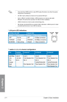
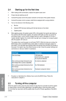
2.4 Starting up for the first time 1. After making all the connections, replace the system case cover. 2. Ensure that all switches are off. 3. Connect the power cord to the power connector at the back of the system chassis. 4. Connect the power cord to a power outlet that is equipped with a surge protector. 5. Turn on the devices in the following order: a. Monitor b. External SCSI devices (starting with the last device on the chain) c. System power 6. After applying power, the system power LED on the system front panel case lights up. For systems with ATX power supplies, the system LED lights up when you press the ATX power button. If your monitor complies with the "green" standards or if it has a "power standby" feature, the monitor LED may light up or change from orange to green after the system LED turns on. The system then runs the power-on self tests (POST). While the tests are running, the BIOS beeps (refer to the BIOS beep codes table) or additional messages appear on the screen. If you DO NOT see anything within 30 seconds from the time you turned on the power, the system may have failed a power-on test. Check the jumper settings and connections or call your retailer for assistance. BIOS Beep One short beep One continuous beep followed by two short beeps then a pause (repeated) One continuous beep followed by three short beeps One continuous beep followed by four short beeps Description VGA detected Quick boot set to disabled No keyboard detected No memory detected No VGA detected Hardware component failure 7. At power on, hold down the key to enter the BIOS Setup. Follow the instructions in Chapter 3. 2.5 Turning off the computer While the system is ON, press the power button for less than four seconds to put the system on sleep mode or soft-off mode, depending on the BIOS setting. Press the power switch for more than four seconds to let the system enter the soft-off mode regardless of the BIOS setting. Chapter 2 2-18 Chapter 2: Basic Installation
-
 1
1 -
2
-
3
-
4
-
5
-
6
-
7
-
8
-
9
-
10
-
11
-
12
-
13
-
14
-
15
-
16
-
17
-
18
-
19
-
20
-
21
-
22
-
23
-
24
-
25
-
26
-
27
-
28
-
29
-
30
-
31
-
32
-
33
-
34
-
35
-
36
-
37
-
38
-
39
-
40
-
41
-
42
-
43
-
44
-
45
-
46
-
47
-
48
-
49
-
50
-
51
-
52
-
53
-
54
-
55
-
56
-
57
-
58
-
59
-
60
-
61
-
62
-
63
-
64
-
65
-
66
-
 67
67 -
 68
68 -
 69
69 -
 70
70 -
 71
71 -
 72
72 -
 73
73 -
 74
74 -
 75
75 -
 76
76 -
 77
77 -
78
-
79
-
80
-
81
-
82
-
83
-
84
-
85
-
86
-
87
-
88
-
89
-
90
-
91
-
92
-
93
-
94
-
95
-
96
-
97
-
98
-
99
-
100
-
101
-
102
-
103
-
104
-
105
-
106
-
107
-
108
-
109
-
110
-
111
-
112
-
113
-
114
-
115
-
116
-
117
-
118
-
119
-
120
-
121
-
122
-
123
-
124
-
125
-
126
-
127
-
128
-
129
-
130
-
131
-
132
-
133
-
134
-
135
-
136
-
137
-
138
-
139
-
140
-
141
-
142
-
143
-
144
-
145
-
146
-
147
-
148
-
149
-
150
-
151
-
152
-
153
-
154
-
155
-
156
-
157
-
158
-
159
-
160
-
161
-
162
-
163
-
164
-
165
-
166
-
167
-
168
-
169
-
170
-
171
-
172
-
173
-
174
-
175
-
176
-
177
-
178
-
179
-
180
 |
 |