Asus MAXIMUS VII HERO User Guide
Asus MAXIMUS VII HERO Manual
 |
View all Asus MAXIMUS VII HERO manuals
Add to My Manuals
Save this manual to your list of manuals |
Asus MAXIMUS VII HERO manual content summary:
- Asus MAXIMUS VII HERO | User Guide - Page 1
Motherboard MAXIMUS VII HERO - Asus MAXIMUS VII HERO | User Guide - Page 2
TO CHANGE AT ANY TIME WITHOUT NOTICE, AND SHOULD NOT BE CONSTRUED AS A COMMITMENT BY ASUS. ASUS ASSUMES NO RESPONSIBILITY OR LIABILITY FOR ANY ERRORS OR INACCURACIES THAT MAY APPEAR IN THIS MANUAL, INCLUDING THE PRODUCTS AND SOFTWARE DESCRIBED IN IT. Products and corporate names appearing in this - Asus MAXIMUS VII HERO | User Guide - Page 3
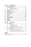
2.1.3 CPU heatsink and fan assembly installation 2-4 2.1.4 DIMM installation 2-6 2.1.5 ATX Power connection 2-7 2.1.6 SATA device connection 2-8 2.1.7 Front I/O Connector 2-9 2.1.8 Expansion Card installation 2-10 2.2 BIOS update utility 2-11 2.3 Motherboard rear and audio connections - Asus MAXIMUS VII HERO | User Guide - Page 4
Boot menu 3-44 3.9 Tool menu 3-50 3.9.1 ASUS EZ Flash 2 Utility 3-50 3.9.2 ROG Secure Erase 3-50 3.9.3 Graphics Card Information 3-52 3.9.4 ASUS Overclocking Profile 3-52 3.9.5 ASUS SPD Information 3-53 3.9.6 ROG OC Panel H-Key Configure 3-54 3.10 Exit menu 3-55 3.11 Updating BIOS - Asus MAXIMUS VII HERO | User Guide - Page 5
4-43 Chapter 5: RAID support 5.1 RAID configurations 5-1 5.1.1 RAID definitions 5-1 5.1.2 Installing Serial ATA hard disks 5-2 5.1.3 Setting the RAID item in BIOS 5-2 5.1.4 Intel® Rapid Storage Technology Option ROM utility 5-3 5.2 Creating a RAID driver disk 5-7 5.2.1 Creating a RAID - Asus MAXIMUS VII HERO | User Guide - Page 6
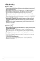
supply is broken, do not try to fix it by yourself. Contact a qualified service technician or your retailer. Operation safety • Before installing the motherboard and adding devices on it, carefully read all the manuals that came with the package. • Before using the product, ensure all cables are - Asus MAXIMUS VII HERO | User Guide - Page 7
of the support DVD that comes with the motherboard package and the software. • Chapter 5: RAID support This chapter describes the RAID configurations. Where to find more information Refer to the following sources for additional information and for product and software updates. 1. ASUS website The - Asus MAXIMUS VII HERO | User Guide - Page 8
of the following symbols used throughout this manual. DANGER/WARNING: Information to prevent injury to yourself when trying to complete a task. CAUTION: Information to prevent damage to the components when trying to complete a task IMPORTANT: Instructions that you MUST follow to complete a task - Asus MAXIMUS VII HERO | User Guide - Page 9
MAXIMUS VII HERO specifications summary CPU Chipset Memory Expansion slots VGA Multi-GPU support LGA1150 socket for 4th/ New 4th/ 5th Generation Intel® Core™ i7/Intel® Core™ i5/ Intel® Core™ i3, Pentium®, and Celeron® processors Supports 22nm CPU Supports Intel® Turbo Boost Technology 2.0 * The - Asus MAXIMUS VII HERO | User Guide - Page 10
panel, 5 ports at mid-board)** * Supports ASUS USB 3.0 Boost, UASP standard on the Intel® native USB 3.0 is only supported under Windows® 8 / 8.1. ** 1 x USB 2.0 port (USB13) shares with ROG extension (ROG_EXT) port. 1 x PS/2 keyboard/mouse combo port 2 x USB 2.0 ports 1 x USB BIOS Flashback button - Asus MAXIMUS VII HERO | User Guide - Page 11
- Disk Unlocker ASUS EZ DIY - Push Notice - USB BIOS Flashback - ASUS CrashFree BIOS 3 - ASUS EZ Flash 2 - ASUS C.P.R. (CPU Parameter Recall) MemOK! ASUS Q-Design - ASUS Q-Code - ASUS Q-Shield - ASUS Q-Connector - ASUS Q-LED (CPU, DRAM, VGA, Boot Device LED) - ASUS Q-Slot - ASUS Q-DIMM (continued - Asus MAXIMUS VII HERO | User Guide - Page 12
BIOS Features Manageability Software Form Factor 1 x USB 3.0 connector (supports additional two USB 3.0 ports) 3 x USB 2.0 connectors (support additional five USB 2.0 ports, one connector shares with ROG_EXT header) 1 x ROG Extension (ROG_EXT) header 8 x SATA 6Gb/s connectors 1 x 4-pin CPU fan - Asus MAXIMUS VII HERO | User Guide - Page 13
for the following items. Motherboard Cables Accessories Application DVD Documentation ROG MAXIMUS VII HERO 3 x 2-in-1 SATA 6 Gb/s cables 1 x SLI® bridge 1 x I/O Shield 1 x 12-in-1 ROG cable label 1 x 2-in-1 Q-Connector kit 1 x ROG Door Hanger ROG motherboard support DVD User guide If any of the - Asus MAXIMUS VII HERO | User Guide - Page 14
(cross) screwdriver PC chassis Power supply unit Intel LGA 1150 CPU Intel LGA 1150 compatible CPU Fan DDR3 DIMM SATA hard disk drive SATA optical disc drive (optional) Graphics card (optional) The tools and components in the table above are not included in the motherboard package. xiv - Asus MAXIMUS VII HERO | User Guide - Page 15
unique PCIe 3.0 bridge chip to support multi-GPU SLI®/ CrossFireX™ graphics cards for an unrivalled gaming performance. With the Intel® Z97 platform to optimize the PCIe allocation of multiple GPUs, it supports up to 2-WAY GPU SLI® or CrossFireX™ configuration. Chapter 1 ASUS MAXIMUS VII HERO 1-1 - Asus MAXIMUS VII HERO | User Guide - Page 16
the operating system. The M.2 slot provides support for faster access to data and applications, and quicker wake up time for your system. • Supports PCIe interface only. • Supports 2260 (22 mm x 60 mm) and 2280 (22 mm x 80 mm) SSD cards. Complete USB 3.0 integration This motherboard offers you the - Asus MAXIMUS VII HERO | User Guide - Page 17
lower CPU utilization for a smooth networking experience. It has advanced features including advanced interrupt-handling, low-power consumption, and Intel Stable Image Platform Program (SIPP) support thanks to its compatibility with the Intel CPU and chipset. Chapter 1 ASUS MAXIMUS VII HERO 1-3 - Asus MAXIMUS VII HERO | User Guide - Page 18
data speeds for compatible USB 3.0 peripherals without the need for any user interaction. USB BIOS Flashback USB BIOS Flashback offers a hassle-free updating solution for your ultimate convenience. Install a USB storage device containing the BIOS file, press the BIOS Flashback button for about - Asus MAXIMUS VII HERO | User Guide - Page 19
in CPU Level UP, XMP, or directly to BIOS mode. This feature supports USB keyboards only. Kaspersky® Anti-Virus Kaspersky® Anti-Virus Personal CD, DVD and Blu-ray discs. It converts optical media into virtual discs and emulates devices to work with the virtual copies. 1 ASUS MAXIMUS VII HERO 1-5 - Asus MAXIMUS VII HERO | User Guide - Page 20
note of the following precautions before you install motherboard components or change any motherboard settings. • Unplug the power cord from the bag that came with the component. • Before you install or remove any component, ensure that the ATX power supply is switched off or the power cord is - Asus MAXIMUS VII HERO | User Guide - Page 21
1.2.2 Motherboard layout Chapter 1 Refer to Internal connectors and Rear I/O connection for more information about rear panel connectors and internal connectors. ASUS MAXIMUS VII HERO 1-7 - Asus MAXIMUS VII HERO | User Guide - Page 22
chassis, and optional fan connectors (4-pin CPU_FAN; 4-pin CPU_OPT; 4-pin CHA_FAN1-4) 4. DDR3 DIMM slots 5. Q_Code LEDs 6. START (Power-on) button 7. MemOK! button 8. RESET button 9. KeyBot button (KeyBot) 10. USB 3.0 connector (20-1 pin USB3_12) 11. M.2 (Socket 3) 12. Intel® Z97 Serial ATA 6 Gb - Asus MAXIMUS VII HERO | User Guide - Page 23
(RMA) requests only if the motherboard comes with the cap on the LGA1150 socket. • The product warranty does not cover damage to the socket contacts resulting from incorrect CPU installation/removal, or misplacement/loss/incorrect removal of the PnP cap. ASUS MAXIMUS VII HERO 1-9 Chapter 1 - Asus MAXIMUS VII HERO | User Guide - Page 24
1.2.4 System memory The motherboard comes with four Double Data Rate 3 (DDR3) Dual Inline Memory Modules (DIMM) slots. A DDR3 module is notched differently from a DDR or DDR2 module. DO NOT install a DDR or DDR2 memory module to the DDR3 slot. Recommended memory configurations Chapter 1 1-10 - Asus MAXIMUS VII HERO | User Guide - Page 25
the vendor-marked or at a higher frequency, refer to section 3.4 Extreme Tweaker menu for manual memory frequency adjustment. • For system stability, use a more efficient memory cooling system to support a full memory load (4 DIMMs) or overclocking condition. Chapter 1 ASUS MAXIMUS VII HERO 1-11 - Asus MAXIMUS VII HERO | User Guide - Page 26
MAXIMUS VII HERO Motherboard Qualified Vendors Lists (QVL) DDR3 3200 MHz capability Vendors Part No. SS - - 12-14-14-35 1.65V 8GB (2x 4GB) SS - - 12-14-14-36 1.65V DIMM socket support (Optional) 2 4 • • • • DDR3 3000 MHz capability Vendors Part No. Size SS/ DS Chip Chip Brand NO. - Asus MAXIMUS VII HERO | User Guide - Page 27
DS DS DS - - 12-13-13-35 - 12-13-13-35 - 12-13-13-35 - 11-13-13-35 Voltage DIMM socket support (Optional) 2 4 - • • - • • - • • 1.65 • • DS DS SS - - 10-12-12-31 1.65 11-31 Voltage DIMM socket support (Optional) 2 4 1.65 • • Chapter 1 ASUS MAXIMUS VII HERO 1-13 - Asus MAXIMUS VII HERO | User Guide - Page 28
- 2400-10-12- 12-28 - 2400-11-13- 13-32 - 2400-11-12- 11-29 Voltage DIMM socket support (Optional) 24 1.65 • • 1.65 • • - • • - • • 1.65 • • 1.65 • • 1.65 • • 1.65 • • 1.65 • • 1.65 • • 1.65 • 1.65 • • 1.65 • 1.65 • • 1.65 • • 1.65 • • 1.65 - Asus MAXIMUS VII HERO | User Guide - Page 29
TX2133KLN-8GK(XMP) 8GB (2x 4GB) SS/ DS Chip Brand Chip NO. Timing Voltage DIMM socket support (Optional) 2 4 SS - - 10-11-11-30 1.65 • • DS - - 10- support (Optional) 24 1.65 • • H5TQ2G83BFRH9C 9-9-9-27 - - 9-9-9-28 1.65 • • • • Chapter 1 ASUS MAXIMUS VII HERO 1-15 - Asus MAXIMUS VII HERO | User Guide - Page 30
Power SP008GXLYU186NSA(XMP) 8GB (2x 4GB) 4GB 8GB SS/ DS Chip Brand Chip NO. Timing Voltage DIMM socket support (Optional) 24 DS - - 1866 9-9-9-27 1.5 • DS - - 9-10-9-27 1.5 • • DS - - 9-10-9-27 1.5 • • DS - - 9-10-9-27 1.5 • • DS - - - 1.5 • • DS - - 9-10-9-27 - Asus MAXIMUS VII HERO | User Guide - Page 31
927 9-1111-28 9-9-927 - Voltage 1.5 1.5 1.5 1.5 1.65 1.65 1.65 • DIMM socket support (Optional) 2 4 • • • • • • • • • • • • • • • • • • • • • • • • • • • • • • • • • • • • • • • • • • (continued on the next page) Chapter 1 ASUS MAXIMUS VII HERO 1-17 - Asus MAXIMUS VII HERO | User Guide - Page 32
24 1.5 9-9-9-28 - 9-9-9-28 - - - - - 9-9-9-28 - 9-9-9-28 - Voltage • DIMM socket support (Optional) 24 • • • • • • • • • • • • • • • • • • • • • • • • • • • • • • • • • • • • • • • • • • • Chapter 1 1-18 Chapter 1: Product introduction - Asus MAXIMUS VII HERO | User Guide - Page 33
- - - - - - Chip NO. 9-9-924 9-9-924 Timing Voltage DIMM socket support (Optional) 2 4 1.25 • • 1.5 • • 9-9-9- 1.5 • • 24 KINGSTON D2568JPUCPGGBU 11-11- - • • 11-28-1 Hynix H5TQ2G83CFRPBC - 1.5 • • (continued on the next page) Chapter 1 ASUS MAXIMUS VII HERO 1-19 - Asus MAXIMUS VII HERO | User Guide - Page 34
- 1600-9-9-9-27 - 1600-9-9-9-27 Timing Voltage DIMM socket support (Optional) 2 4 1.5 • - • • - • - • - • • - • • 1.5 • • 1.5 • • - • - • - • • 1.5 • • - • • - • • 1.5 • • 1.5 • - • • - • • TED34GM1600C11BK 4GB DS Hynix H5TC2G83EFR 11-11 - Asus MAXIMUS VII HERO | User Guide - Page 35
24 9-9-9-24 9-9-9-24 9-9-9-24 9 9-9-9-24 9-9-9-24 9-9-9-24 9-9-9-24 9-9-9-24 Voltage DIMM socket support (Optional - • • - • • 1.5 • • 1.5 • 1.5 • • - • • 1.5 • • 1.5 • • 1.5 • • 1.5 • • 1.5 • • (continued on the next page) Chapter 1 ASUS MAXIMUS VII HERO 1-21 - Asus MAXIMUS VII HERO | User Guide - Page 36
DDR3 1333 MHz capability Vendors Part No. Size SS/ DS Chip Brand Chip NO. Timing Voltage DIMM socket support (Optional) 24 GEIL GG34GB1333C9DC 4GB DS GEIL (2x2GB) GL1L128M88BA115FW 9-9-9-24 1.3 •• GEIL GG34GB1333C9DC 4GB DS GEIL (2x2GB) GL1L128M88BA15B 9-9-9-24 1.3 •• GEIL - Asus MAXIMUS VII HERO | User Guide - Page 37
. • ASUS exclusively provides hyper DIMM support function. • Hyper DIMM support is subject to the physical characteristics of individual CPUs. Load the X.M.P. settings in the BIOS for the hyper DIMM support. • Visit the ASUS website for the latest QVL. Chapter 1 ASUS MAXIMUS VII HERO 1-23 - Asus MAXIMUS VII HERO | User Guide - Page 38
. Failure to do so may cause you physical injury and damage motherboard components. Chapter 1 Slot No. Slot Description 1 PCIe 2.0 x1_1 slot 2 PCIe 3.0/2.0 x16/x8_1 slot 3 PCIe 2.0 x1_2 slot 4 PCIe 3.0/2.0 x8_2 slot 5 PCIe 2.0 x1_3 slot 6 PCIe 2.0 x4_3 slot 1-24 Chapter 1: Product introduction - Asus MAXIMUS VII HERO | User Guide - Page 39
motherboard connector labeled CHA_FAN1-4 when using multiple graphics cards for better thermal environment. • New 4th and 5th generation Intel® Core™ processors support PCIe 3.0 speed rate. PCIe_x16/x8_1 slot switches to x8 mode when PCIe_x8_2 slots are occupied. Chapter 1 ASUS MAXIMUS VII HERO - Asus MAXIMUS VII HERO | User Guide - Page 40
~3 are disabled. • In PCIe X4 Mode, the PCIeX4_3 slot runs at X4 mode for high performance support. PCIeX1_1~3, and M.2 connector are disabled. • To configure the PCIEx4_3 slot bandwidth option in BIOS, refer to the Onboard Devices Configuration section on the BIOS Setup chapter. 1-26 - Asus MAXIMUS VII HERO | User Guide - Page 41
up when the system is plugged to a power source indicating that you should shut down the system and unplug the power cable before removing or installing any motherboard component. 2. RESET button (RESET) Press the reset button to reboot the system. Chapter 1 ASUS MAXIMUS VII HERO 1-27 - Asus MAXIMUS VII HERO | User Guide - Page 42
up due to BIOS overclocking, press the MemOK! button to boot and load the BIOS default settings. A message will appear during POST reminding you that the BIOS has been restored to its default settings. • We recommend that you download and update to the latest BIOS version from the ASUS website at - Asus MAXIMUS VII HERO | User Guide - Page 43
hangs due to overclocking. 5. KeyBot button (KeyBot) Press this button to activate the KeyBot feature. • The KeyBot feature supports USB keyboards only. • For more information about the KeyBot feature, refer to the Software Support chapter of this user guide. ASUS MAXIMUS VII HERO 1-29 Chapter - Asus MAXIMUS VII HERO | User Guide - Page 44
the Sonic SoundStage feature. • The debug code on the Q-Code LED shows the current Sonic SoundStage profile when you press the Sonic SoundStage button. • For more information about Sonic SoundStage, refer to the Software Support chapter of this user guide. Chapter 1 1-30 Chapter 1: Product - Asus MAXIMUS VII HERO | User Guide - Page 45
DRAM, VGA card, and booting devices) in sequence during motherboard booting process. If an error is found, the corresponding LED flashes until the problem is solved. This user-friendly design provides an intuitive way to locate the root problem within seconds. Chapter 1 ASUS MAXIMUS VII HERO 1-31 - Asus MAXIMUS VII HERO | User Guide - Page 46
3. KeyBot LED (KEYBOT_LED) This LED lights up when the KeyBot button is pressed. 4. USB BIOS Flashback LED (FLBK_LED) This LED flashes when you press the BIOS Flashback button for BIOS update. Chapter 1 1-32 Chapter 1: Product introduction - Asus MAXIMUS VII HERO | User Guide - Page 47
5. Q-Code LEDs The Q-Code LED design provides you with a 2-digit error code that displays the system status. Refer to the Q-Code table on the following page for details. Chapter 1 ASUS MAXIMUS VII HERO 1-33 - Asus MAXIMUS VII HERO | User Guide - Page 48
memory type or incompatible memory speed Unspecified memory initialization error Memory not installed Invalid CPU type or Speed CPU mismatch CPU self test failed or possible CPU cache error CPU micro-code is not found or micro-code update is failed (continued on the next page) Chapter 1 1-34 - Asus MAXIMUS VII HERO | User Guide - Page 49
DXE IPL) S3 Boot Script execution Video repost OS S3 wake vector call Reserved for future AMI progress codes S3 Resume Failed S3 Resume PPI not Found S3 Resume Boot Script Error S3 OS Wake Error Reserved for future AMI error codes (continued on the next page) Chapter 1 ASUS MAXIMUS VII HERO 1-35 - Asus MAXIMUS VII HERO | User Guide - Page 50
Code table Code F0 F1 F2 F3 F4 F5 - F7 F8 F9 FA FB - FF 60 61 62 error codes DXE Core is started NVRAM initialization Installation of the PCH Runtime Services codes Boot Device Selection (BDS) phase is started Driver connecting is started PCI Bus initialization is started PCI Bus Hot Plug Controller - Asus MAXIMUS VII HERO | User Guide - Page 51
Codes section below) Ready To Boot event Legacy Boot event Exit Boot Services event Runtime Set Virtual Address MAP Begin Runtime Set Virtual Address MAP End Legacy Option ROM Initialization System Reset USB hot plug PCI bus hot plug (continued on the next page) Chapter 1 ASUS MAXIMUS VII HERO - Asus MAXIMUS VII HERO | User Guide - Page 52
ROM No Console Output Devices are found No Console Input Devices are found Invalid password Error loading Boot Option (LoadImage returned error) Boot Option is failed (StartImage returned error) Flash update is failed Reset protocol is not available ACPI/ASL Checkpoints Code 0x01 0x02 0x03 0x04 - Asus MAXIMUS VII HERO | User Guide - Page 53
SATA Configuration for details. • Before creating a RAID set, refer to section RAID configurations or the manual bundled in the motherboard support DVD. • When using NCQ, set the SATA Mode in the BIOS to [AHCI Mode]. Refer to section SATA Configuration for details. ASUS MAXIMUS VII HERO 1-39 - Asus MAXIMUS VII HERO | User Guide - Page 54
time for USB-chargeable devices, optimized power efficiency, and backward compatibility with USB 2.0. Chapter 1 The USB 3.0 module is purchased separately. • These connectors are based on xHCI specification. We recommend you to install the related driver to fully use the USB 3.0 ports under - Asus MAXIMUS VII HERO | User Guide - Page 55
the front panel USB cable to the ASUS Q-Connector (USB) first, and then install the Q-Connector (USB) to the USB connector onboard if your chassis supports front panel USB ports. 1 x USB 2.0 ports (USB13) at mid-board shares with ROG extension (ROG_EXT) port. Chapter 1 ASUS MAXIMUS VII HERO 1-41 - Asus MAXIMUS VII HERO | User Guide - Page 56
connector is for a chassis-mounted front panel audio I/O module that supports either HD Audio or legacy AC`97 audio standard. Connect one end high-definition front panel audio module to this connector to avail of the motherboard's high-definition audio capability. • If you want to connect a high- - Asus MAXIMUS VII HERO | User Guide - Page 57
may damage the motherboard components. These are not jumpers! Do not place jumper caps on the fan connectors! • Ensure to fully insert the 4-pin CPU fan cable to the CPU fan connector. The CPU_FAN connector supports the CPU fan of maximum 1A (12 W) fan power. Chapter 1 ASUS MAXIMUS VII HERO 1-43 - Asus MAXIMUS VII HERO | User Guide - Page 58
use a PSU with a higher power output when configuring a system with more power-consuming devices. The system may become unstable or may not boot up if the power is inadequate. • If you want to use two or more high-end PCIe x16 cards, use a PSU with 1000W power or above to ensure the system - Asus MAXIMUS VII HERO | User Guide - Page 59
supports drive ATX BIOS settings. Pressing the power button for more than four seconds while the system is ON turns the system OFF. • Reset button (2-pin RESET) This 2-pin connector is for the chassis-mounted reset button for system reboot without turning off the system power. ASUS MAXIMUS VII HERO - Asus MAXIMUS VII HERO | User Guide - Page 60
Panel, Front Base, and the other ROG device. • The OC Panel and Front Base are purchased separately. • Visit www.asus.com for more information about the OC Panel and Front Base. 10. TPM connector (20-1 pin TPM) This connector supports a Trusted - Asus MAXIMUS VII HERO | User Guide - Page 61
cable that allows you to monitor the temperature of your motherboard's critical components and connected devices. 12. M.2 (Socket 3) The M.2 (Socket 3) with M Key supports type 2260 (22 mm x 60 mm) and 2280 (22 mm x 80 mm) PCIe interface storage devices. Chapter 1 ASUS MAXIMUS VII HERO 1-47 - Asus MAXIMUS VII HERO | User Guide - Page 62
Chapter 1 1-48 Chapter 1: Product introduction - Asus MAXIMUS VII HERO | User Guide - Page 63
may vary with models, but the installation steps are the same for all models. 1. Install the ASUS Q-Shield to the chassis rear I/O panel. 2. Place the motherboard into the chassis, ensuring that its rear I/O ports are aligned to the chassis' rear I/O panel. Chapter 2 ASUS MAXIMUS VII HERO 2-1 - Asus MAXIMUS VII HERO | User Guide - Page 64
3. Place nine screws into the holes indicated by circles to secure the motherboard to the chassis. Chapter 2 DO NOT over tighten the screws! Doing so can damage the motherboard. 2-2 Chapter 2: Basic Installation - Asus MAXIMUS VII HERO | User Guide - Page 65
2.1.2 CPU installation Ensure that you install the correct CPU designed for LGA1150 socket only. DO NOT install a CPU designed for LGA1155 and LGA1156 sockets on the LGA1150 socket. 1 A B 2 3 Chapter 2 4 5 C A B ASUS MAXIMUS VII HERO 2-3 - Asus MAXIMUS VII HERO | User Guide - Page 66
2.1.3 CPU heatsink and fan assembly installation Apply the Thermal Interface Material to the CPU heatsink and CPU before you install the heatsink and fan if necessary. To install the CPU heatsink and fan assembly Chapter 2 2-4 Chapter 2: Basic Installation - Asus MAXIMUS VII HERO | User Guide - Page 67
To uninstall the CPU heatsink and fan assembly Chapter 2 ASUS MAXIMUS VII HERO 2-5 - Asus MAXIMUS VII HERO | User Guide - Page 68
2.1.4 1 DIMM installation 2 3 To remove a DIMM B A 2-6 Chapter 2: Basic Installation Chapter 2 - Asus MAXIMUS VII HERO | User Guide - Page 69
2.1.5 1 ATX Power connection 2 OR Chapter 2 ASUS MAXIMUS VII HERO 2-7 - Asus MAXIMUS VII HERO | User Guide - Page 70
2.1.6 1 SATA device connection OR 2 Chapter 2 2-8 Chapter 2: Basic Installation - Asus MAXIMUS VII HERO | User Guide - Page 71
2.1.7 Front I/O Connector To install ASUS Q-Connector 1 2 To install USB 2.0 connector To install front panel audio connector USB 2.0 To install USB 3.0 connector USB 3.0 ASUS MAXIMUS VII HERO AAFP 2-9 Chapter 2 - Asus MAXIMUS VII HERO | User Guide - Page 72
2.1.8 Expansion Card installation To install PCIe x16 cards Chapter 2 2-10 Chapter 2: Basic Installation - Asus MAXIMUS VII HERO | User Guide - Page 73
Connect your USB keyboard on the KeyBot port if you want to use the KeyBot feature. Updating BIOS may have risks. If the BIOS program is damaged during the process and results to the system's failure to boot up, please contact your local ASUS Service Center. Chapter 2 ASUS MAXIMUS VII HERO 2-11 - Asus MAXIMUS VII HERO | User Guide - Page 74
1. PS/2 Keyboard/Mouse combo port 2. Optical S/PDIF OUT port 3. VGA port 4. Intel® USB 3.0 ports 3 and 4. Lower port supports USB BIOS Flasback feature. 5. LAN (RJ-45) port* 6. Intel® USB 2.0 ports 7 and 8. Upper port supports the KeyBot feature. 7. HDMI port 8. DVI port 9. USB BIOS Flashback button - Asus MAXIMUS VII HERO | User Guide - Page 75
USB 3.0 ports for faster and better performance for your USB 3.0 devices. • Due to the design of the Intel® 9 series chipset, all USB devices connected to the USB 2.0 and USB 3.0 ports are controlled by the xHCI controller. Some legacy USB devices must update their firmware for better compatibility - Asus MAXIMUS VII HERO | User Guide - Page 76
Connect to Headphone and Mic Connect to Stereo Speakers Connect to 2.1 channel Speakers Chapter 2 2-14 Chapter 2: Basic Installation - Asus MAXIMUS VII HERO | User Guide - Page 77
Connect to 4.1 channel Speakers Connect to 5.1 channel Speakers Chapter 2 ASUS MAXIMUS VII HERO 2-15 - Asus MAXIMUS VII HERO | User Guide - Page 78
Connect to 7.1 channel Speakers Chapter 2 2-16 Chapter 2: Basic Installation - Asus MAXIMUS VII HERO | User Guide - Page 79
ON, press the power button for less than four seconds to put the system on sleep mode or soft-off mode, depending on the BIOS setting. Press the power button for more than four seconds to let the system enter the soft-off mode regardless of the BIOS setting. Chapter 2 ASUS MAXIMUS VII HERO 2-17 - Asus MAXIMUS VII HERO | User Guide - Page 80
Chapter 2 2-18 Chapter 2: Basic Installation - Asus MAXIMUS VII HERO | User Guide - Page 81
Inappropriate BIOS settings may result to instability or boot failure. We strongly recommend that you change the BIOS settings only with the help of a trained service personnel. When downloading or updating the BIOS file, rename it as M7H.CAP for this motherboard. Chapter 3 ASUS MAXIMUS VII HERO - Asus MAXIMUS VII HERO | User Guide - Page 82
fails to boot after changing any BIOS setting, try to clear the CMOS and reset the motherboard to the default value. See section Onboard buttons for more information on how to erase the RTC RAM via the Clear CMOS button. • The BIOS setup program does not support the bluetooth devices. BIOS menu - Asus MAXIMUS VII HERO | User Guide - Page 83
to manually tune the fans Loads optimized default settings Saves the changes and resets the system Click to go to Advanced mode Click to display boot devices Selects the boot device priority The boot device options vary depending on the devices you installed to the system. ASUS MAXIMUS VII HERO - Asus MAXIMUS VII HERO | User Guide - Page 84
provides advanced options for experienced end-users to configure the BIOS settings. The figure below shows an example of the Pop-up Menu Menu bar Language Quick Note (F9) Scroll bar MyFavorite(F3) Qfan Control(F6) EZ Tuning Wizard(F11) Hot Keys Chapter 3 Sub-menu item Menu items General - Asus MAXIMUS VII HERO | User Guide - Page 85
, Boot, manually tweak the fans to your desired settings. EZ Tuning Wizard(F11) This button above the menu bar allows you to view and tweak the overclocking settings of your system. It also allows you to change the motherboard's SATA mode from AHCI to RAID mode. Chapter 3 ASUS MAXIMUS VII HERO - Asus MAXIMUS VII HERO | User Guide - Page 86
of the activities that you have done in BIOS. • The quick Note function does not support the following keyboard functions: delete, cut, copy and paste. item. Use key to capture the BIOS screen and save it to the removable storage device. Configuration fields These fields show the values for - Asus MAXIMUS VII HERO | User Guide - Page 87
access your favorite BIOS items. Adding items to My Favorites To add frequently-used BIOS items to My Favorites: 1. Press on your keyboard or click to as language and boot order • Configuration items such as Memory SPD Information, system time and date. ASUS MAXIMUS VII HERO 3-7 Chapter 3 - Asus MAXIMUS VII HERO | User Guide - Page 88
installed on the motherboard. Scroll down to display other BIOS items. Chapter 3 Ai Overclock Tuner [Auto] Allows you to select the CPU overclocking options system. [Manual] Allows you to individually set overclocking parameters. [X.M.P.] If you install memory modules supporting the eXtreme - Asus MAXIMUS VII HERO | User Guide - Page 89
.0 MHz. When Ai Overclock Tuner is set to [XMP], the XMP mode supported by the installed memory module is displayed. ASUS MultiCore Enhancement [Auto] setting or manually assign a 4-Core Limit value that must be higher than or equal to the 3-Core Ratio Limit. ASUS MAXIMUS VII HERO 3-9 Chapter 3 - Asus MAXIMUS VII HERO | User Guide - Page 90
the value. The values depend on the CPU installed. Max. CPU Cache Ratio [Auto] Allows you on the CPU installed. Internal PLL Overvoltage [Auto] This item CPUs to get the extreme overclocking capability. Configuration options: [ the CPU Graphics Ratio or manually set a value for an optimal - Asus MAXIMUS VII HERO | User Guide - Page 91
The CPU level values depends on the CPU installed in your system. EPU Power Saving Mode [ timing control features. Use the and keys to adjust the value. To restore the default setting, type [auto] using the keyboard and options: [Auto] [1] - [15] Chapter 3 ASUS MAXIMUS VII HERO 3-11 - Asus MAXIMUS VII HERO | User Guide - Page 92
[15] DRAM CAS# Write Latency [Auto] Configuration options: [Auto] [1] - [31] RTL IOL control DRAM RTL Initial Value [Auto] Configuration options: [Auto] [1] - [63] DRAM RTL(CHA_R0D0) - [15] Third Timings tRDRD [Auto] Configuration options: [Auto] [1] - [7] tRDRD_dr [Auto] 3-12 Chapter 3: BIOS setup - Asus MAXIMUS VII HERO | User Guide - Page 93
configuration options: [Enable Both DIMMS] [Disable DIMM0] [Disable DIMM1] [Disable Both DIMMS] Scramble Setting [Optimized (ASUS)] Set this item to [Optimized (ASUS)] to enhance system stability. Configuration options: [Optimized (ASUS)] [Default (MRC)] Chapter 3 ASUS MAXIMUS VII HERO 3-13 - Asus MAXIMUS VII HERO | User Guide - Page 94
] Receiver Control Time [Auto] Configuration options: [Auto] GPU.DIMM Post Automatically detects and displays the information about the devices or memory installed on the PCIe and DIMM slots. The field shows N/A if there are no devices installed on the slots. Chapter 3 3-14 Chapter 3: BIOS setup - Asus MAXIMUS VII HERO | User Guide - Page 95
[Auto] This item allows you to set the power phase control of the CPU. Configuration options: [Auto] [Standard] [Optimized] [Extreme] DO NOT remove the thermal module when setting this item to [Power Phase Response]. The thermal conditions should be monitored. Chapter 3 ASUS MAXIMUS VII HERO 3-15 - Asus MAXIMUS VII HERO | User Guide - Page 96
help BCLK Overclock. Configuration options: [Auto] [0.0000] - [3.0000] PLL Termination Reset Voltage [Auto] PLL Termination Reset Voltage. Voltage [Auto] Power Supply for the Integrated Clock Controller. Lower may be better. Clock Crossing Boot Voltage [Auto] The instantaneous voltage value when the - Asus MAXIMUS VII HERO | User Guide - Page 97
ratio and features. Enhanced Intel SpeedStep Technology [Enabled] higher current limit to prevent frequency and power throttling when overclocking. Use the and keys to adjust the 0% to 6%. CPU Internal Power Fault Control Thermal Feedback [Auto] Allows the CPU ASUS MAXIMUS VII HERO 3-17 - Asus MAXIMUS VII HERO | User Guide - Page 98
work manual override manual 00] - [1.50] CPU Internal Power Saving Control Power Saving Level 1 Threshold [Auto] Lower value provides sufficient overclocking tolerance to enlarge the overclocking overclocking tolerance to enlarge the overclocking overclocking tolerance to enlarge the overclocking - Asus MAXIMUS VII HERO | User Guide - Page 99
Graphics Voltage [Auto] Configures the amount of Voltage fed to the onboard graphics unit on the processor. Increase when increasing IGPU Frequency. Configuration options: [Auto] [Manual Mode] [Offset Mode [Adaptive Mode] Chapter 3 ASUS MAXIMUS VII HERO 3-19 - Asus MAXIMUS VII HERO | User Guide - Page 100
when you set the CPU Graphics Voltage to [Manual Mode]. CPU Graphics Voltage Override [Auto] This voltage fed to the system agent of the CPU including its PCIE controller and the PCU (power control unit). Increase the voltage to enhance the overclocking capability. You can use the or keys to - Asus MAXIMUS VII HERO | User Guide - Page 101
. SVID Support [Auto] Set this item to [Enabled] when overclocking your system Intel® CPU specifications, DIMMs with voltage requirement over 1.65 V may damage the CPU permanently. We recommend that you install the DIMMs with the voltage requirement below 1.65 V. Chapter 3 ASUS MAXIMUS VII HERO - Asus MAXIMUS VII HERO | User Guide - Page 102
Controller Hub). You can use the or keys to adjust the value. The values range from 0.70 V to 1.80 V with a 0.0125 V interval. • The values of the CPU PLL Voltage, CPU Manual Voltage, CPU Offset Voltage, iGPU Manual (Platform Controller Hub). on the control lines from overclocking overclocking - Asus MAXIMUS VII HERO | User Guide - Page 103
3.5 Main menu The Main menu screen appears when you enter the Advanced Mode of the BIOS Setup program. The Main menu provides you an overview of the basic system information, and allows you to set the system date, time, language, and security settings. Chapter 3 ASUS MAXIMUS VII HERO 3-23 - Asus MAXIMUS VII HERO | User Guide - Page 104
BIOS password, erase the CMOS Real Time Clock (RTC) RAM to clear the BIOS password. See section 1.2.6 Onboard buttons and switches for information on how to erase the RTC RAM via the Clear CMOS button. • The Administrator or User Password items on top of the screen show the default [Not Installed - Asus MAXIMUS VII HERO | User Guide - Page 105
password for accessing the system. Otherwise, you might be able to see or change only selected fields in the BIOS setup program. To set an administrator password: 1. Select the Administrator Password User Password item on top of the screen shows Not Installed. Chapter 3 ASUS MAXIMUS VII HERO 3-25 - Asus MAXIMUS VII HERO | User Guide - Page 106
3.6 Advanced menu The Advanced menu items allow you to change the settings for the CPU and other system devices. Be cautious when changing the settings of the Advanced menu items. Incorrect field values can cause the system to malfunction. Chapter 3 3-26 Chapter 3: BIOS setup - Asus MAXIMUS VII HERO | User Guide - Page 107
information that the BIOS automatically detects. The items in this menu may vary based on the CPU installed. Chapter 3 Intel Adaptive Thermal Monitor OS to boot even without support for CPUs with extended CPUID functions. Configuration options: [Disabled] [Enabled] ASUS MAXIMUS VII HERO 3-27 - Asus MAXIMUS VII HERO | User Guide - Page 108
Disable prevents certain classes of malicious buffer overflow attacks when combined with a supporting OS (SuSE Linux 9.2, RedHat Enterprise 3 Update 3). Configuration options: [Disabled] [Enabled] Intel Virtualization Technology [Disabled] When set to [Enabled], a VMM can utilize the additional - Asus MAXIMUS VII HERO | User Guide - Page 109
duration of C7 latency for C7 state. Configuration options: [Short] [Long] Package C-States Support [Auto] This item allows you to set the a C-state support for the CPU package. Configuration options: [Auto] [Enabled] [C0/C1] [C2] [C3] [C6] [CPU C7] [CPU C7s] Chapter 3 ASUS MAXIMUS VII HERO 3-29 - Asus MAXIMUS VII HERO | User Guide - Page 110
partition size is not enough for the Intel® Rapid Start Technology to work. Configuration options: [Enabled] [Disabled] Active Memory Threshold [0] This item only appears when Active Page Threshold Support is set to [Enabled]. This item supports Intel Rapid Storage Technology when the partition size - Asus MAXIMUS VII HERO | User Guide - Page 111
] 3.6.3 PCH Storage Configuration While entering Setup, the BIOS automatically detects the presence of SATA devices. The SATA Port items show Empty if no SATA device is installed to the corresponding SATA port. Scroll down to display the other BIOS items. Chapter 3 ASUS MAXIMUS VII HERO 3-31 - Asus MAXIMUS VII HERO | User Guide - Page 112
a warning message during POST (Power-on Self Test) when an error occurs in the hard disks. Press to set this item On or Off. Configuration options: [On] [Off] SATA6G_1 (Red) - SATA6G_6 (Red) Press to rename the Intel SATA ports. SATA6G_1 (Red) - SATA6G_6 (Red) [Enabled] This item - Asus MAXIMUS VII HERO | User Guide - Page 113
graphical devices. Primary Display [Auto] [Auto] [CPU Graphics] [PCIE] The primary display will be set to PCI-E when a PCI-E graphic card is detected. Force the primary display to be from the CPU Graphics. Force the primary display to be from the PCI-E graphic cards. ASUS MAXIMUS VII HERO - Asus MAXIMUS VII HERO | User Guide - Page 114
[512M] Render Standby [Auto] Allows you to enable the Intel® Graphics Render Standby support to reduce iGPU power use when the system is idle. port speed. [Gen1] The PCI-EX16 port will run at PCI-E 1.0 speed. [Gen2] The PCI-EX16 port will run at PCI-E 2.0 speed. [Gen3] The PCI-EX16 port - Asus MAXIMUS VII HERO | User Guide - Page 115
EHCI drivers for operating systems with EHCI support. Support EHCI by BIOS for operating systems without EHCI support. USB Single Port Control Allows you to enable or disable the individual USB ports. Refer to the Motherboard layout section for the location of the USB ports. ASUS MAXIMUS VII HERO - Asus MAXIMUS VII HERO | User Guide - Page 116
the Windows Vista operating system to control the Active State Power Management (ASPM) support for devices. [Enabled] Vista controls the ASPM support for the device. [Disabled] BIOS controls the ASPM support for the device. PCH - PCI Express DMI Link ASPM Control [Disabled] This item is for - Asus MAXIMUS VII HERO | User Guide - Page 117
connector (AAFP) mode to legacy AC'97 SPDIF Out Type [SPDIF] [SPDIF] Sets to an SPDIF audio output. [HDMI] Sets to an HDMI audio output. ASUS MAXIMUS VII HERO 3-37 - Asus MAXIMUS VII HERO | User Guide - Page 118
connector is disabled. [M.2 Mode] PCIeX4_3 slot runs at X2 mode for M.2 connector support. PCIeX1_1~3 are disabled. [PCIe X4 Mode] PCIeX4_3 slot runs at X4 mode for high performance support. PCIeX1_1~3 and M.2 connector are disabled. Intel LAN Controller [Enabled] This item allows you to - Asus MAXIMUS VII HERO | User Guide - Page 119
devices. [Enabled] Enables the PCIE/PCI devices to generate a wake-on-LAN feature of the PCIE LAN devices. Power On By RTC [Disabled] [Disabled] Disables RTC to generate a wake event. [Enabled] Generates a wake event and configure the real-time clock (RTC) alarm date. ASUS MAXIMUS VII HERO - Asus MAXIMUS VII HERO | User Guide - Page 120
when you set the Network Stack to [Enabled]. Ipv4/Ipv6 PXE Support [Enabled] Allows you to enable or disable the Ipv4/Ipv6 PXE boot option. Configuration options: [Disabled] [Enabled] 3.6.10 ROG Effects Chapter by your setting. Configuration options: [Enabled] [Disabled] 3-40 Chapter 3: BIOS setup - Asus MAXIMUS VII HERO | User Guide - Page 121
fan. Anti Surge Support fan speed in rotations per minute (RPM). If any of the fans is not connected to the motherboard, the field shows [N/A]. These items are not user‑configurable. Press and select [Ignore] if you do not wish to display the detected temperatures. ASUS MAXIMUS VII HERO - Asus MAXIMUS VII HERO | User Guide - Page 122
of CPU fan installed and automatically switches the mode control. When a 3-pin CPU fan is installed, select this mode for the DC mode Q-Fan control. Enables the CPU Q-Fan control feature in PWM mode for 4-pin CPU fan. Disables the Q-Fan control. [PWM Mode] Disables the Q-Fan control. The following - Asus MAXIMUS VII HERO | User Guide - Page 123
. Chassis Fan 1/2/3/4 Fan Middle. Duty Cycle (%) [60] Use the or keys to adjust the maximum CPU fan duty cycle. The values range from 20% to 100%. When the CPU temperature reaches the upper limit, the CPU fan will operate at the maximum duty cycle. Chapter 3 ASUS MAXIMUS VII HERO 3-43 - Asus MAXIMUS VII HERO | User Guide - Page 124
function allows the fan to run at 0% duty cycle when the temperature of the source is dropped below the lower temperature. Configuration options. [Disabled] [Enabled] 3.8 Boot menu The Boot menu items allow you to change the system boot options. Scroll down to display the other BIOS items. Chapter - Asus MAXIMUS VII HERO | User Guide - Page 125
, only USB ports with keyboard and mouse connections will be detected. PS/2 Keyboard and Mouse Support [Auto] Allows you to disable or have full system control of the PS/2 devices' availability during POST. Configuration options: [Auto] [Disabled] [Full Initialization] Network Stack Driver Support - Asus MAXIMUS VII HERO | User Guide - Page 126
BIOS Setup. You can only execute the POST delay time during normal boot. The values range from 0 to 10 seconds. This feature only works when set under normal boot. Boot or disables 64-bit capable devices to be decoded in above 4G address space if your system supports 64-bit PCI Decoding. - Asus MAXIMUS VII HERO | User Guide - Page 127
Boot check. Only select this option when booting on Windows® UEFI mode or other Microsoft® Secure Boot compliant OS. Get the optimized function when booting on Windows® nonUEFI mode. Microsoft® Secure Boot only supports Windows® UEFI mode. Clear Secure Boot keys Chapter 3 ASUS MAXIMUS VII HERO - Asus MAXIMUS VII HERO | User Guide - Page 128
Boot keys. This item allows you to clear all default Secure Boot keys. Save Secure Boot Keys This item allows you to save the PK (Platform Keys) to a USB storage device db from a USB storage device. Append Default db Allows you to load the additional db from a storage device so that more images - Asus MAXIMUS VII HERO | User Guide - Page 129
when ASUS Logo appears. Boot Override These items displays the available devices. The number of device items that appears on the screen depends on the number of devices installed in the system. Click an item to start booting from the selected device. Chapter 3 ASUS MAXIMUS VII HERO 3-49 - Asus MAXIMUS VII HERO | User Guide - Page 130
the contents of your SSD may take a while depending on its size. Do not turn off the system during the process. • Secure Erase is only supported on Intel SATA port. For more information about Intel SATA ports, refer to section 1.2.2 of this manual. 3-50 Chapter 3: BIOS setup Chapter 3 - Asus MAXIMUS VII HERO | User Guide - Page 131
BIOS protective measure. The BIOS guards drives that do not have password protection by freezing them prior to booting. If the drive is frozen, a power off or hard reset by ASUS. You have to unlock the SSD in the software before proceeding with Secure Erase. Chapter 3 ASUS MAXIMUS VII HERO 3-51 - Asus MAXIMUS VII HERO | User Guide - Page 132
This item displays the information about the graphics card installed in your system. 3.9.4 ASUS Overclocking Profile This item allows you to store or load multiple BIOS settings. Chapter 3 Profile Name Key in the profile name to save current BIOS settings to profile 1 to 8. Save to Profile Saves - Asus MAXIMUS VII HERO | User Guide - Page 133
DRAM SPD information. DIMM slot number Allows you to select the DIMM slot number to show the plugged DRAM Serial Presence Detect (SPD) information. Configuration options: [DIMM_A1] [DIMM_A2] [DIMM_B1] [DIMM_ B2] Some DRAM manufacturers may not be recognized. Chapter 3 ASUS MAXIMUS VII HERO 3-53 - Asus MAXIMUS VII HERO | User Guide - Page 134
H-Key Configure allows you to input and save values on the CPU core voltage, CPU input voltage, BCLK Frequency, and CPU ratio in the UEFI BIOS. The saved values can be synchronized to a compatible OC Panel device and these values can be tweaked or configured using the OC Panel without going to the - Asus MAXIMUS VII HERO | User Guide - Page 135
appears. Select Yes to load the default values. Save Changes & Reset Once you are finished making your selections, choose this option from device This option allows you to attempt to launch the EFI Shell application (shellx64.efi) from one of the available filesystem devices. ASUS MAXIMUS VII HERO - Asus MAXIMUS VII HERO | User Guide - Page 136
EZ Update: Updates the BIOS in Windows® environment. 2. ASUS EZ Flash 2: Updates the BIOS using a USB flash drive. 3. ASUS CrashFree BIOS 3: Restores the BIOS using the motherboard support DVD or a USB flash drive when the BIOS file fails or gets corrupted. 4. ASUS BIOS Updater: Updates the BIOS in - Asus MAXIMUS VII HERO | User Guide - Page 137
that contains the latest BIOS, and then press . 5. Press to switch to the Folder Info field. 6. Press the Up/Down arrow keys to find the BIOS file, and then press to perform the BIOS update process. Reboot the system when the update process is done. ASUS MAXIMUS VII HERO 3-57 - Asus MAXIMUS VII HERO | User Guide - Page 138
support.asus.com and save it to a USB flash drive. Recovering the BIOS To recover the BIOS: 1. Turn on the system. 2. Insert the motherboard support DVD to the optical drive, or the USB flash drive containing the BIOS file to the USB port. 3. The utility automatically checks the devices for the BIOS - Asus MAXIMUS VII HERO | User Guide - Page 139
BIOS Updater to the USB port. 2. Boot your computer then press to launch the select boot device screen. 3. When the select boot device screen appears, insert the Support DVD into the optical drive then select the optical drive as the boot device. Please select boot device: E1: ASUS DVD-E818A6T - Asus MAXIMUS VII HERO | User Guide - Page 140
> to switch from Files panel to Drives panel then select D:. Drives panel ASUSTeK BIOS Updater for DOS V1.30 [2014/01/01] Current ROM BOARD: MAXIMUS VII HERO VER: 0210 (H :00 B :00) DATE: 02/12/2014 PATH: C:\ Update ROM BOARD: Unknown VER: Unknown DATE: Unknown C: FORMAN~1 D: M7H.CAP - Asus MAXIMUS VII HERO | User Guide - Page 141
reset the system while updating the BIOS to prevent system boot failure. Ensure to load the BIOS default settings to ensure system compatibility and stability. Select the Load Optimized Defaults item under the Exit BIOS menu. See section 3.10 Exit menu for details. Chapter 3 ASUS MAXIMUS VII HERO - Asus MAXIMUS VII HERO | User Guide - Page 142
Chapter 3 3-62 Chapter 3: BIOS setup - Asus MAXIMUS VII HERO | User Guide - Page 143
DVD into the optical drive. 2. In the AutoPlay dialog box, click Run ASSETUP.exe. Chapter 4 If the AutoPlay dialog box does not appear, browse the contents of the support DVD and double-click or tap \\bin\ASSETUP.EXE to launch the ASUS motherboard support DVD main menu. ASUS MAXIMUS VII HERO - Asus MAXIMUS VII HERO | User Guide - Page 144
and other software that the motherboard supports. Shows the available device drivers if the system detects installed devices. Install the necessary drivers to use the devices. Contains the list of supplementary user manuals. Click an item to open the folder of the user guide. Contains ROG related - Asus MAXIMUS VII HERO | User Guide - Page 145
3 on your computer: Windows® 7 OS 1. Place the Support DVD into the optical drive. 2. In the AutoPlay dialog box, click Run ASSETUP.exe then select the Utilities tab Chapter 4 3. From the Utilities tab, click AI Suite 3 then follow the succeeding onscreen instructions. ASUS MAXIMUS VII HERO 4-3 - Asus MAXIMUS VII HERO | User Guide - Page 146
the succeeding onscreen instructions. If the ASUS motherboard support DVD main menu did not appear, try the following steps: a. Go to the Start Screen then click or tap the Desktop app. b. On the lower left corner of the Desktop, click or tap File Explorer then select your DVD drive and tap or - Asus MAXIMUS VII HERO | User Guide - Page 147
BIOS Push Notice Flashback Version • Some functions in the AI Suite 3 main menu in this user guide may vary depending on the motherboard model. • Refer to the software manual in the support DVD or visit the ASUS website at www.asus.com for detailed software configuration. ASUS MAXIMUS VII HERO - Asus MAXIMUS VII HERO | User Guide - Page 148
Dual Intelligent Processors 5 ASUS Dual Intelligent Processors 5 combines TPU, EPU, DIGI+ Power Control, Fan Xpert 3, and Turbo App functions to push the system's performance to its optimal potential. It automatically balances the system's performance, power saving, levels, and fan settings via the - Asus MAXIMUS VII HERO | User Guide - Page 149
• Set the CPU Ratio Setting item in BIOS to [Auto] before using the CPU Frequency in TPU. Refer to the BIOS chapter of your motherboard's user guide for details. • The CPU Frequency bars show the status of the CPU cores, which vary with your CPU model. Chapter 4 ASUS MAXIMUS VII HERO 4-7 - Asus MAXIMUS VII HERO | User Guide - Page 150
GPU Boost CPU Graphics Voltage Adjustments Click to load the saved profile Click to save the Click to enable the adjustment into a profile default settings Click to apply the adjustments Click to undo the adjustments Chapter 4 4-8 Chapter 4: Software support - Asus MAXIMUS VII HERO | User Guide - Page 151
to adjust the configured Max CPU Power Click to select a fan profile Tick to select a setting for Voltage Decrement Click to However, the true CPU frequency varies depending on the wattage that you manually set. You can adjust the CPU wattage from the lowest base on 4 ASUS MAXIMUS VII HERO 4-9 - Asus MAXIMUS VII HERO | User Guide - Page 152
screens are for reference only. Configuration options varies depending on the motherboard model. Click or tap to switch Click or tap to undo between screens the changes Click or tap to apply the changes CPU Power Phase Control Increase the phase number under a heavy system load to get more - Asus MAXIMUS VII HERO | User Guide - Page 153
set the fan's speed to silent mode Click to maximize the fan speed Click to set the balanced configuration between the fan's noise level and speed Click to switch between CPU and chassis fan screens Click to increase the fan's speed for a high cooling capability Chapter 4 ASUS MAXIMUS VII HERO - Asus MAXIMUS VII HERO | User Guide - Page 154
List can be configured. Performance pane Allows you to assign the CPU performance to a selected application. Audio pane Allows you to manually assign a preset audio configuration to a selected application. LAN pane Allows you assign the network priority to a selected application. Chapter 4 4-12 - Asus MAXIMUS VII HERO | User Guide - Page 155
automatically detects the USB 3.0 devices that support UASP. For a list of UASP-supported USB 3.0 devices, visit the ASUS website at www.asus.com. • The data transfer speed varies with USB devices. For a higher data transfer performance, use a USB 3.0 device. Chapter 4 ASUS MAXIMUS VII HERO 4-13 - Asus MAXIMUS VII HERO | User Guide - Page 156
is a utility that allows you to automatically update your motherboard's software, drivers, or BIOS. With this utility, you can also manually update the BIOS and select the boot logo that will display during POST. Launching EZ Update To launch EZ Update, click or tap on the top-right corner of - Asus MAXIMUS VII HERO | User Guide - Page 157
information and settings of the installed motherboard, CPU, and memory. Launching motherboard information Click or tap the MB tab to view the motherboard's information. Viewing the CPU information Click or tap the CPU tab to view the processor's information. Chapter 4 ASUS MAXIMUS VII HERO - Asus MAXIMUS VII HERO | User Guide - Page 158
Viewing the SPD information Click or tap the SPD tab to view the memory's information. Chapter 4 4-16 Chapter 4: Software support - Asus MAXIMUS VII HERO | User Guide - Page 159
Launching USB BIOS Flashback To launch USB BIOS Flashback, click or tap main menu, then select USB BIOS Flashback. on the top-right corner of the AI Suite 3 USB BIOS Flashback is available only in selected motherboard models. Using USB BIOS Flashback Set a schedule for the BIOS Update download - Asus MAXIMUS VII HERO | User Guide - Page 160
to connect your USB device into the USB port that supports this utility. Refer to section 2.3.1 Rear I/O connection of your user manual for more details. • USB Charger+ does not support USB hubs, USB extension cables, and generic USB cables. • USB Charger+ may not recognize some ASUS devices due to - Asus MAXIMUS VII HERO | User Guide - Page 161
and smart device: 1. On your smart device, tap to launch Push Notice. Push Notice 2. Tap Push Scan then tap the name of your computer that you want to pair with. To pair your computer and smart device, ensure that both are connected to the same wireless network. Chapter 4 ASUS MAXIMUS VII HERO - Asus MAXIMUS VII HERO | User Guide - Page 162
mode and sends an alert to your smart device. Tick these to enable mode alerts Set the to select the smart device Setting up PC Status alerts This feature allows fan settings of your computer to your smart device. Tick to select and send alerts to your smart device Tick to select the smart device - Asus MAXIMUS VII HERO | User Guide - Page 163
smart device to launch Push Notice. Push Notice Tap to view PC mode alerts Tap to view PC status alerts Tap to view PC sent messages Tap to scan more host computers Tick to select the smart device Click or tap to send your message Tap to delete PC alerts Chapter 4 ASUS MAXIMUS VII HERO 4-21 - Asus MAXIMUS VII HERO | User Guide - Page 164
4.6 ROG Audio features Installing the Software Follow the installation wizard to install the Realtek® Audio Manager driver from the support DVD that is bundled with the motherboard. If the Realtek® audio software is correctly installed, you will find the Realtek® HD Audio Manager icon on the taskbar - Asus MAXIMUS VII HERO | User Guide - Page 165
You can manually set or test for the selected preset profile. Preset profiles Click any of the preset profiles. Choose from Gaming, music, movie, or communication. Profile import/export Allows you to Import, export, or revert to the default setting of a profile. Chapter 4 ASUS MAXIMUS VII HERO - Asus MAXIMUS VII HERO | User Guide - Page 166
headphone's impedance and adjusts the built-in AMP accordingly. Sonic SenseAmp only works on front panel. When you plug a headphone into the front headphone jack is automatically set at Extreme Other device The device plugged in detected as other device 4-24 Chapter 4: Software support Chapter 4 - Asus MAXIMUS VII HERO | User Guide - Page 167
After you close the pop-window, Sonic SenseAmp enters speaker configuration and displays the adjusted headphone impedance. Click to manually adjust the amplify level Displays the impedance of your headphone Chapter 4 ASUS MAXIMUS VII HERO 4-25 - Asus MAXIMUS VII HERO | User Guide - Page 168
. Refer to the section of your motherboard's user guide for the location of the SoundStage button. Click any of the four preset gaming profiles Use the slider to manually adjust the setting of an item Crossing Move the slider to adjust the amount of cross channel mixing. Revert Move the slider - Asus MAXIMUS VII HERO | User Guide - Page 169
DTS Connect DTS Connect delivers excellent audio entertainment across all formats and works with 4, 5.1 and 7.1 channels of incredible surround sound . It also allows you to connect your PC to a home theatre system. Control settings panel Chapter 4 ASUS MAXIMUS VII HERO 4-27 - Asus MAXIMUS VII HERO | User Guide - Page 170
Click a tab to select an option. Each option has its own settings and menus. Click to reset to the default settings Click to start the test tone Use the sliders to adjust the settings Displays the list of games Control Menu Allows you to configure shortcut keys. Chapter 4 4-28 Chapter 4: Software - Asus MAXIMUS VII HERO | User Guide - Page 171
the sound enhancers. Tick to choose the desired sound enhancer Audio Mode/Radar Selection are enabled with shortcut keys in the game. Refer to the Controls tab for more information about the shortcut key settings. Chapter 4 ASUS MAXIMUS VII HERO 4-29 - Asus MAXIMUS VII HERO | User Guide - Page 172
) facilitating different user scenarios. Users can also manually allocate bandwidth and adjust priority settings of each application function on/off Tick to display all the applications. Click to reset and load the default settings of the selected profile Allows you to Chapter 4: Software support - Asus MAXIMUS VII HERO | User Guide - Page 173
the individual downloading and uploading bandwidth of currently used applications. Total usage Displays the total downloading and uploading bandwidth of the currently used applications. Chapter 4 ASUS MAXIMUS VII HERO 4-31 - Asus MAXIMUS VII HERO | User Guide - Page 174
You can use this feature to test the Internet Service Provider (ISP) speed or manually key in the desired uploading/downloading speed and apply the speed if needed. Key in the upload/ download speed Click to begin the speed test Click to apply the speed after manually keying in the desired speed or - Asus MAXIMUS VII HERO | User Guide - Page 175
Connect the USB keyboard into the dedicated KeyBot USB port. Refer to the Rear I/O connection or the USB BIOS Flashback section for more information about the location of the KeyBot USB port. 3. , or click their corresponding keys on the keyboard Smart login Chapter 4 ASUS MAXIMUS VII HERO 4-33 - Asus MAXIMUS VII HERO | User Guide - Page 176
Function Keys Shortcut Chapter 4 4-34 Chapter 4: Software support - Asus MAXIMUS VII HERO | User Guide - Page 177
Streamer. On your device, click or tap Media Streamer. Click or tap to edit media files Click or tap to select media type Log in ASUS account to stream Click or tap a media file to play Select the device you play in different networks want to stream to Chapter 4 ASUS MAXIMUS VII HERO 4-35 - Asus MAXIMUS VII HERO | User Guide - Page 178
Click to delete selected files Click to proceed with the deletion or addition of files Click to cancel changes The following media formats are supported: .3gp, .mp4, .m4a, .aac, .ts, .flac, .mp3, .mid, .xmf, .mxmf, .rtttl, .rtx, .ota, .imy, .ogg, .mkv, .wav, .jpg, .gif, .png, .bmp, .webp, .webm - Asus MAXIMUS VII HERO | User Guide - Page 179
hard disk drives (HDD). ASUS Disk Unlocker is supported only on Windows® 7 and Windows® 8. To launch ASUS Disk Unlocker, click . Click to open the help file that shows the detailed information on how to use ASUS Disk Unlocker ASUS Disk Unlocker Help file Chapter 4 ASUS MAXIMUS VII HERO 4-37 - Asus MAXIMUS VII HERO | User Guide - Page 180
software that reserves a part of your system's memory and turns it into a high-speed virtual drive where you can store cache files and game apps for instant access. The Dynamic Memory Allocation function can release the unused memory of RAMDisk back to the system when needed and helps extend the - Asus MAXIMUS VII HERO | User Guide - Page 181
create your junction point Click the drop-down arrow to select your RAMDisk drive and its available storage space. Click to select where to create a junction point. Click to finish adding the new junction point. Click to delete the existing junction point. Chapter 4 ASUS MAXIMUS VII HERO 4-39 - Asus MAXIMUS VII HERO | User Guide - Page 182
Synchronizing backup files After creating a junction point, RAMDisk automatically creates a backup folder in the file's original location. Use RAMDisk to manually synchronize updates with these backup files. Click Synchronize to update your files Chapter 4 4-40 Chapter 4: Software support - Asus MAXIMUS VII HERO | User Guide - Page 183
compare with other users on the ROG website. MemTweakIt functions depends on the chipset on the motherboard. Each chipset has differernt options. To use MemTweakIt, double-click on the desktop. Click a Click to apply your settings Click to validate your settings. ASUS MAXIMUS VII HERO 4-41 - Asus MAXIMUS VII HERO | User Guide - Page 184
1. Launch MemTweakIt and click Validate. 2. In Manual Mode, click Save Validation File. 3. Key in a file name for your configuration file and click Submit. 4. Click validation webpage. 5. In MemTweakIt - Validation File Upload window, key in your ASUS account ID and password. 6. Click Browse, locate - Asus MAXIMUS VII HERO | User Guide - Page 185
information and status of your CPU, motherboard, memory, graphics card, and other components installed in your system. You can generate a report about your system info and send or post it on the CPU-Z website. To use ROG CPU-Z, double-click on the desktop. Chapter 4 ASUS MAXIMUS VII HERO 4-43 - Asus MAXIMUS VII HERO | User Guide - Page 186
Chapter 4 4-44 Chapter 4: Software support - Asus MAXIMUS VII HERO | User Guide - Page 187
5.1 RAID configurations The motherboard comes with the Intel® Rapid Storage Technology that supports RAID 0, RAID 1, RAID 10 and RAID 5 configuration. If you want to install a Windows® operating system to a hard disk drive included in a RAID set, you have to create a RAID driver disk and load the - Asus MAXIMUS VII HERO | User Guide - Page 188
The motherboard supports Serial ATA hard disk drives. For optimal performance, install identical drives of the same model and capacity when creating a disk array. To install the SATA hard disks for a RAID configuration: 1. Install the SATA hard disks into the drive bays. 2. Connect the SATA signal - Asus MAXIMUS VII HERO | User Guide - Page 189
you to move through the menus and select the menu options. The RAID BIOS setup screens shown in this section are for reference only and may not exactly match the items on your screen. The utility supports maximum four hard disk drives for RAID configuration. Chapter 5 ASUS MAXIMUS VII HERO 5-3 - Asus MAXIMUS VII HERO | User Guide - Page 190
following screen appears: Intel(R) Rapid Storage Technology - Option ROM - v10.5.1.1070 Copyright(C) 2003-10 Intel Corporation. All Rights select the hard disk drives you want to include in the RAID set. The SELECT DISKS screen appears: Port Drive Model 0 ST3160812AS 1 ST3160812AS 5: RAID support - Asus MAXIMUS VII HERO | User Guide - Page 191
, and then press to select. A small triangle marks the selected drive. Press after completing your selection. 6. Use the up/down arrow key to select the stripe RAID volume and return to the main menu, or to go back to the CREATE VOLUME menu. Chapter 5 ASUS MAXIMUS VII HERO 5-5 - Asus MAXIMUS VII HERO | User Guide - Page 192
appears: Name Volume0 [ DELETE VOLUME MENU ] Level Drives RAID0(Stripe) 2 Capacity Status Bootable 298.0GB Normal Yes [ HELP ] Deleting a volume will reset the disks to non-RAID. WARNING: ALL DISK DATA or press to return to the DELETE VOLUME menu. Chapter 5 5-6 Chapter 5: RAID support - Asus MAXIMUS VII HERO | User Guide - Page 193
. 3. Set the optical drive as the primary boot device. 4. Insert the support DVD into the optical drive. 5. Save changes and exit BIOS. 6. When the Make Disk menu appears, press to create a RAID driver disk. 7. Insert a formatted floppy disk into the USB floppy disk drive, then press - Asus MAXIMUS VII HERO | User Guide - Page 194
the USB port or the support DVD into the optical drive, and then click Browse. 3. Click the name of the device you've inserted, go to Drivers > RAID, and then select the RAID driver for the corresponding OS version. Click OK. 4. Follow the succeeding screen instructions to complete the installation - Asus MAXIMUS VII HERO | User Guide - Page 195
This equipment has been tested and found to comply with the limits for a Class B digital device, pursuant to Part installation. This equipment generates, uses and can radiate radio frequency energy and, if not installed and used in accordance with manufacturer's instructions ASUS MAXIMUS VII HERO A-1 - Asus MAXIMUS VII HERO | User Guide - Page 196
RSS standard(s). Operation is subject to the following two conditions: (1) this device may not cause interference, and (2) this device must accept any interference, including interference that may cause undesired operation of the device. Cut appareil numérique de la Classe B est conforme à la norme - Asus MAXIMUS VII HERO | User Guide - Page 197
bin indicates that the battery should not be placed in municipal waste. ASUS Recycling/Takeback Services ASUS recycling and takeback programs express or implied. See the License for the specific language governing permissions and limitations under the License. Appendices ASUS MAXIMUS VII HERO A-3 - Asus MAXIMUS VII HERO | User Guide - Page 198
Telephone +1-510-739-3777 Fax +1-510-608-4555 Web site http://www.asus.com/us/ Technical Support Support fax Telephone Online support +1-812-284-0883 +1-812-282-2787 http://www.service.asus.com/ ASUS COMPUTER GmbH (Germany and Austria) Address Harkort Str. 21-23, D-40880 Ratingen - Asus MAXIMUS VII HERO | User Guide - Page 199
device must accept any interference received, including interference that may cause undesired operation. Representative Person's Name : Steve Chang / President Signature : Date ASUS COMPUTER GmbH HARKORT STR. 21-23, 40880 RATINGEN GERMANY Product name : Motherboard Model name : MAXIMUS VII HERO - Asus MAXIMUS VII HERO | User Guide - Page 200
Appendices A-6 Appendices
-
 1
1 -
 2
2 -
 3
3 -
 4
4 -
 5
5 -
 6
6 -
 7
7 -
8
-
9
-
10
-
11
-
12
-
13
-
14
-
15
-
16
-
17
-
18
-
19
-
20
-
21
-
22
-
23
-
24
-
25
-
26
-
27
-
28
-
29
-
30
-
31
-
32
-
33
-
34
-
35
-
36
-
37
-
38
-
39
-
40
-
41
-
42
-
43
-
44
-
45
-
46
-
47
-
48
-
49
-
50
-
51
-
52
-
53
-
54
-
55
-
56
-
57
-
58
-
59
-
60
-
61
-
62
-
63
-
64
-
65
-
66
-
67
-
68
-
69
-
70
-
71
-
72
-
73
-
74
-
75
-
76
-
77
-
78
-
79
-
80
-
81
-
82
-
83
-
84
-
85
-
86
-
87
-
88
-
89
-
90
-
91
-
92
-
93
-
94
-
95
-
96
-
97
-
98
-
99
-
100
-
101
-
102
-
103
-
104
-
105
-
106
-
107
-
108
-
109
-
110
-
111
-
112
-
113
-
114
-
115
-
116
-
117
-
118
-
119
-
120
-
121
-
122
-
123
-
124
-
125
-
126
-
127
-
128
-
129
-
130
-
131
-
132
-
133
-
134
-
135
-
136
-
137
-
138
-
139
-
140
-
141
-
142
-
143
-
144
-
145
-
146
-
147
-
148
-
149
-
150
-
151
-
152
-
153
-
154
-
155
-
156
-
157
-
158
-
159
-
160
-
161
-
162
-
163
-
164
-
165
-
166
-
167
-
168
-
169
-
170
-
171
-
172
-
173
-
174
-
175
-
176
-
177
-
178
-
179
-
180
-
181
-
182
-
183
-
184
-
185
-
186
-
187
-
188
-
189
-
190
-
191
-
192
-
193
-
194
-
195
-
196
-
197
-
198
-
199
-
200
 |
 |

Motherboard
MAXIMUS VII
HERO