Asus NCL-DS User Guide
Asus NCL-DS Manual
 |
View all Asus NCL-DS manuals
Add to My Manuals
Save this manual to your list of manuals |
Asus NCL-DS manual content summary:
- Asus NCL-DS | User Guide - Page 1
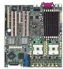
Motherboard NCL-DS Series NCL-DS NCL-D NCL-DR1 - Asus NCL-DS | User Guide - Page 2
OR DATA, INTERRUPTION OF BUSINESS AND THE LIKE), EVEN IF ASUS HAS BEEN ADVISED OF THE POSSIBILITY OF SUCH DAMAGES ARISING FROM ANY DEFECT OR ERROR IN THIS MANUAL OR PRODUCT. SPECIFICATIONS AND INFORMATION CONTAINED IN THIS MANUAL ARE FURNISHED FOR INFORMATIONAL USE ONLY, AND ARE SUBJECT TO CHANGE - Asus NCL-DS | User Guide - Page 3
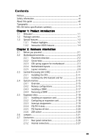
ix NCL-DS Series specifications summary x Chapter 1: Product introduction 1.1 Welcome 1-1 1.2 Package contents 1-1 1.3 Special features 1-2 1.3.1 Product highlights 1-2 1.3.2 Innovative ASUS features 1-4 Chapter 2: Hardware information 2.1 Before you proceed 2-1 2.2 Motherboard overview - Asus NCL-DS | User Guide - Page 4
a bootable floppy disk 4-1 4.1.2 AFUDOS utility 4-2 4.1.3 ASUS CrashFree BIOS 2 utility 4-5 4.1.4 ASUS Update utility 4-7 4.2 BIOS setup program 4-10 4.2.1 BIOS 4.4.6 Onboard Devices Configuration 4-24 4.4.7 PCI PnP 4-25 4.5.1 ACPI APIC Support [Enabled 4-27 4.5.2 APM Configuration 4-27 iv - Asus NCL-DS | User Guide - Page 5
4.5 Power menu 4-27 4.5.3 Hardware Monitor 4-30 4.6.1 Boot Device Priority 4-32 4.6 Boot menu 4-32 4.6.2 Boot Settings Configuration 4-33 4.6.3 Security 4-35 4.7 Exit menu 4-38 Appendix: Block diagrams A.1 NCL-DS block diagram A-1 A.2 NCL-D block diagram A-2 A.3 NCL-DR1 block diagram A-3 v - Asus NCL-DS | User Guide - Page 6
and, if not installed and used in accordance with manufacturer's instructions, may cause harmful interference to radio communications. However, there is reception, which can be determined by turning the equipment off and on, the user is encouraged to try to correct the interference by one or more of - Asus NCL-DS | User Guide - Page 7
signal cables from the motherboard, ensure that all service technician or your retailer. Operation safety • Before installing the motherboard and adding devices on it, carefully read all the manuals screws, and staples away from connectors, slots, sockets and circuitry. • Avoid dust, humidity, and - Asus NCL-DS | User Guide - Page 8
guide This user guide contains the information you need when installing and configuring the motherboard. How this guide is organized This manual contains the following parts: • Chapter 1: Product introduction This chapter describes the features of the motherboard and the new technologies it supports - Asus NCL-DS | User Guide - Page 9
manual. D A N G E R / W A R N I N G : Information to prevent injury to yourself when trying to complete a task. C A U T I O N : Information to prevent damage to the components when trying to complete a task. I M P O R T A N T : Instructions command line: afudos /i[filename] afudos /iNCL-DS.ROM ix - Asus NCL-DS | User Guide - Page 10
NCL-DS Series specifications summary CPU Chipset Front Side Bus Memory Expansion slots Storage Dual 604-pin sockets for Intel® Xeon™ processors with Extended Memory 64-bit Technology (EM64T) Supports Intel® Hyper-Threading Technology Northbridge : Intel® E7520 Memory Controller Hub (MCH) - Asus NCL-DS | User Guide - Page 11
connector SCSI connectors (NCL-DS model only) Backplane SMBus connector System panel connector SSI power supply (with 24-pin and 8-pin 12V plugs) ATX 12V 2.0 compliant E-ATX form factor: 12 in x 13 in (30.5 cm x 33 cm) Device drivers ASUS Live Update Utility Anti-virus software *Specifications are - Asus NCL-DS | User Guide - Page 12
xii - Asus NCL-DS | User Guide - Page 13
This chapter describes the motherboard features and the new technologies it supports. 1Product introduction - Asus NCL-DS | User Guide - Page 14
Chapter summary 1 1.1 Welcome 1-1 1.2 Package contents 1-1 1.3 Special features 1-2 ASUS NCL-DS Series - Asus NCL-DS | User Guide - Page 15
cables 1 x Serial ATA power cable (dual-plug) 2 x SCSI Ultra320 cables (for NCL-DS model only) 80-conductor IDE cable 3-in-1 floppy disk drive cable Accessories Application CDs Documentation 2 x CEK spring (for CPUs) I/O shield ASUS motherboard support CD User guide If any of the above items is - Asus NCL-DS | User Guide - Page 16
only) The Adaptec® AIC-7902 PCI-X SCSI controller is onboard to support two 68-pin Ultra320 SCSI connectors, each can connect up to 15 devices. See page 2-29 for details. Zero-Channel RAID (ZCR) solution (NCL-DS model only) The motherboard comes with a ZCR socket for an optional Zero-Channel RAID - Asus NCL-DS | User Guide - Page 17
details. Serial ATA technology The motherboard supports the Serial ATA technology through the Serial ATA interfaces controlled by the Intel® ICH5R. The SATA specification allows for thinner, more flexible cables of current for critical components. See page 4-31 for details. ASUS NCL-DS Series 1-3 - Asus NCL-DS | User Guide - Page 18
you to restore the original BIOS data from the support CD in case when the BIOS codes and data are corrupted. This protection eliminates the need to buy a replacement ROM chip. See page 4-5 for details. ASUS Smart Fan technology The ASUS Smart Fan technology smartly adjusts the fan speeds according - Asus NCL-DS | User Guide - Page 19
This chapter lists the hardware setup procedures that you have to perform when installing system components. It includes description of the jumpers and connectors on the motherboard. 2 Hardware information - Asus NCL-DS | User Guide - Page 20
Chapter summary 2 2.1 Before you proceed 2-1 2.2 Motherboard overview 2-2 2.3 Central Processing Unit (CPU 2-11 2.4 System memory 2-15 2.5 Expansion slots 2-18 2.6 Jumpers 2-21 2.7 Connectors 2-26 ASUS NCL-DS Series - Asus NCL-DS | User Guide - Page 21
install motherboard components or change any motherboard settings. • Unplug the power cord from the wall socket before motherboard component. The illustration below shows the location of the onboard LED. SB_PWR1 ON Standby Power OFF Powered Off NCL-DS Series Standby power LED ASUS NCL-DS - Asus NCL-DS | User Guide - Page 22
sure to unplug the chassis power cord before installing or removing the motherboard. Failure to do so can cause you physical injury and damage motherboard components. 2.2.1 Placement direction When installing the motherboard, make sure that you place it into the chassis in the correct orientation - Asus NCL-DS | User Guide - Page 23
motherboard. Socket for CPU1 Socket for CPU2 Heatsink hole 2. Position the CEK spring underneath the motherboard, then match the CEK spring hooks to the CPU1 heatsink holes. 3. Press the upper spring hooks inward, then insert to the upper CPU heatsink holes until they snap in place. ASUS NCL-DS - Asus NCL-DS | User Guide - Page 24
steps 2 to 4 to install the CEK spring to the CPU2 heatsink holes. The CEK springs appear as shown when installed. 6. Before installing the motherboard into the chassis, locate the standoffs that should match the eight (8) CEK spring screw holes. CEK spring screw hole Standoffs for CPU1 Standoffs - Asus NCL-DS | User Guide - Page 25
standoffs. Socket for CPU1 Socket for CPU2 Make sure that the standoffs perfectly match the CEK spring screw holes; otherwise, you can not install the CPU heatsinks properly. 8. Secure the motherboard with 9 screws. Refer to section "2.2.2 Screw holes" for illustration. ASUS NCL-DS Series 2-5 - Asus NCL-DS | User Guide - Page 26
30.5cm (12in) ® 2.2.4 Motherboard layouts NCL-DS model mPGA 604 33cm (13in) PS/2 T: Mouse B: Keyboard ATXPWR1 REAR_FAN2 PSUSMB1 1 35 SCSIA1 NCL-DS The NCL-DS model includes Adaptec® AIC-7902W SCSI controller, SCSI connectors, and Intel® PXH chipset to support the SCSI RAID feature. 2-6 - Asus NCL-DS | User Guide - Page 27
133MHz 3V) VGA_EN1 PCIE3 CPU2 J2 Intel PXH CPU_FAN2 FM_CPU2 SEC_IDE PRI_IDE Intel ICH5R mPGA 604 ATI PCIX4 (64-bit, 133MHz 3V) RAGE XL VGA Controller PCIX5 (64-bit, The NCL-D model supports RAID feature through the Intel® ICH5R southbridge and two SATA connectors. ASUS NCL-DS Series - Asus NCL-DS | User Guide - Page 28
) DDR DIMM_A1 (64/72 bit, 240-pin module) ATX12V1 FM_CPU1 VGA1 COM1 mPGA 604 RJ-45 (LAN-1) RJ-45 (LAN-2) REAR_FAN1 Broadcom BCM5721 Intel E7520 MCH RECPVERY1 PANEL1 USBPW34 SATA2 SATA1 FRNT_FAN1 FRNT_FAN2 NCL-DR1 • The NCL-DR1 model supports RAID feature through the Intel® ICH5R - Asus NCL-DS | User Guide - Page 29
Layout contents Slots/Sockets 1. CPU sockets 2. DDR2 DIMM sockets 3. PCI/PCI-X/PCI Express slots 4. Zero-Channel RAID socket Jumpers 1. 7. Gigabit LAN controller setting (3-pin LAN2_EN1) 8. SCSI controller setting (3-pin SCSI_EN1) 9. Force BIOS recovery 2-26 2-26 2-26 2-26 ASUS NCL-DS Series 2-9 - Asus NCL-DS | User Guide - Page 30
disk drive connector (34-1 pin FLOPPY1) 2. Primary IDE connectors (40-1 pin PRI_IDE, SEC_IDE) 3. Serial ATA connectors (7-pin SATA1, SATA2) 4. Ultra320 SCSI connectors (two 68-pin SCSIA1, SCSIB1) 5. Hard disk activity LED connector (4-pin HDLED1) 6. USB connector (10-1 pin USB34) 7. CPU and system - Asus NCL-DS | User Guide - Page 31
cache. The new generation Xeon™ processor supports 800 MHz system bus and Extended Memory 64-bit Technology (EM64T). 2.3.1 Installling the CPU To install a CPU: 1. Locate the CPU sockets on the motherboard. Intel Xeon Gold Arrow Pin A1 NCL-DS Series CPU Socket 604 If installing only one CPU, use - Asus NCL-DS | User Guide - Page 32
it fits in place. The CPU fits only in one correct orientation. DO NOT force the CPU into the socket to prevent bending the pins and damaging the CPU! 5. Carefully push down the socket lever to secure the CPU. The lever clicks on the side tab to indicate that it is locked - Asus NCL-DS | User Guide - Page 33
to the top of the CPU before installing the heatsink and fan. • Refer to the installation manual that came with the CPU package for details on heatsink/fan assembly and installation. CPU heatsink (top four screws on the heatsink align with the nuts on the support plate. ASUS NCL-DS Series 2-13 - Asus NCL-DS | User Guide - Page 34
2. Use a Phillips screwdriver to tighten the four heatsink screws in a diagonal sequence. 3. Connect the fan cable to the 4-pin connector labeled CPU_FAN1. Do not forget to connect the CPU fan connector! Hardware monitoring errors may occur if you fail to plug this connector. CPU_FAN1 connector - Asus NCL-DS | User Guide - Page 35
DDR2 memory modules. • This motherboard does not support memory modules made up of 128 Mb chips or double-rank x16 memory modules. • If you are installing only one memory module, install into the blue socket labeled DIMM_B4. Installing into any other socket would not work. ASUS NCL-DS Series 2-15 - Asus NCL-DS | User Guide - Page 36
Single rank population MCH Single and dual rank mixing MCH Dual rank population MCH Single Rank DIMM B4 Single Rank DIMM A4 Single Rank DIMM B3 Single Rank DIMM A3 Single Rank DIMM B2 Single Rank DIMM A2 Single Rank DIMM B1 Single Rank DIMM A1 Dual Rank DIMM B4 Dual Rank DIMM A4 Single Rank DIMM - Asus NCL-DS | User Guide - Page 37
press the retaining clips outward to unlock the DIMM. Support the DIMM lightly with your fingers when pressing the retaining clips. The DIMM might get damaged when it 1 flips out with extra force. 2. Remove the DIMM from the socket. 2 1 DDR2 DIMM notch ASUS NCL-DS Series 2-17 - Asus NCL-DS | User Guide - Page 38
settings for the card. 2. Remove the system unit cover (if your motherboard is already installed in a chassis). 3. Remove the bracket opposite the page. 3. Install the software drivers for the expansion card. When using PCI cards on shared slots, ensure that the drivers support "Share IRQ" or that - Asus NCL-DS | User Guide - Page 39
PCI steering* PS/2 Compatible Mouse Port* Numeric Data Processor Primary IDE Channel Secondary IDE Channel * These IRQs are usually available for ISA or PCI devices. ASUS NCL-DS Series 2-19 - Asus NCL-DS | User Guide - Page 40
high performance add-on cards like SCSI RAID card, fiber-channel card, etc. 2.5.6 ZCR socket The ZCR socket on the motherboard supports the Adaptec AIC-2015 Zero-Channel RAID card that allows RAID0, RAID1, RAID10, and RAID 5 configurations. 2-20 The NCL-DS and NCL-D models include all slots. The - Asus NCL-DS | User Guide - Page 41
to clear the Real Time Clock (RTC) RAM in CMOS. You can clear the CMOS memory of date, time, and system setup parameters by erasing the CMOS RTC RAM data. The onboard will cause system boot failure! NCL-DS Series Clear RTC RAM CLRTC1 12 23 Normal (Default) Clear CMOS ASUS NCL-DS Series 2-21 - Asus NCL-DS | User Guide - Page 42
NCL-DS Series USB device wake up USBPW34 2 1 +5V (Default) 3 2 +5VSB • The USB device wake-up feature requires a power supply that can provide 500mA on the +5VSB lead for each USB port; otherwise, the system would not power up. • If you are using Windows 2000, you need to install Service - Asus NCL-DS | User Guide - Page 43
and a corresponding setting in the BIOS. KBPWR1 12 23 +5V (Default) +5VSB NCL-DS Series Keyboard power setting 5 . VGA controller setting (3-pin VGA_EN1) These jumpers allow you the VGA feature. NCL-DS Series VGA setting VGA_EN1 1 2 Enable (Default) 2 3 Disable ASUS NCL-DS Series 2-23 - Asus NCL-DS | User Guide - Page 44
disable the onboard Broadcom® BCM5751 Gigabit LAN1 controller. Set to pins 1-2 to activate the Gigabit LAN feature. LAN1_EN1 1 2 Enable (Default) NCL-DS Series LAN1_EN setting 2 3 Disable 7 . Gigabit LAN controller setting (3-pin LAN2_EN1) These jumpers allow you to enable or disable the onboard - Asus NCL-DS | User Guide - Page 45
) This jumper allows you to enable or disable the onboard Adaptec® AIC-7902 SCSI U320 controller. Set to pins 1-2 to activate the SCSI feature, and support RAID configurations. NCL-DS Series SCSI setting SCSI_EN1 12 23 Enable (Default) Disable 9 . Force BIOS recovery setting (3-pin RECOVERY1 - Asus NCL-DS | User Guide - Page 46
is for a PS/2 mouse. 2 . P a r a l l e l p o r t . This 25-pin port connects a parallel printer, a scanner, or other devices. (present in NCL-DS and NCL-D models only) 3 . L A N ( R J - 4 5 ) p o r t s . These ports allow Gigabit connection to a Local Area Network (LAN) through a network hub. Refer - Asus NCL-DS | User Guide - Page 47
. This prevents incorrect insertion when you connect the IDE cable. • Use the 80-conductor IDE cable for Ultra DMA 100/66 IDE devices. NCL-DS Series IDE connectors ASUS NCL-DS Series SEC_IDE PIN 1 PRI_IDE PIN 1 NOTE: Orient the red markings (usually zigzag) on the IDE ribbon cable to PIN 1. 2-27 - Asus NCL-DS | User Guide - Page 48
RSATA_TXN2 RSATA_TXP2 GND GND RSATA_RXP1 RSATA_RXN1 GND RSATA_TXN1 RSATA_TXP1 GND SATA2 SATA1 NCL-DS Series SATA connectors Important notes on Serial ATA • You must install Windows® 2000 Service Pack 4 or the Windows® XP Service Pack 1 before using Serial ATA hard disk drives. The Serial ATA RAID - Asus NCL-DS | User Guide - Page 49
connectors (two 68-pin SCSIA1, SCSIB1) (present in NCL-DS model only) This motherboard comes with the Adaptec® AIC-7902 SCSI U320 controller that support two 68-Pin Ultra320 SCSI connectors, one for each of the two channels. Each channel can support a maximum of 15 devices as specified by Ultra320 - Asus NCL-DS | User Guide - Page 50
the SATA connectors cause this LED to light up. HDLED1 1 NCL-DS Series SCSI/SATA card activity LED connector 6. USB connector (10-1 pin USB34 complies with USB 2.0 specification that supports up to 480 Mbps connection speed. GND USB PortA(+) USB PortA(-) Power NCL-DS Series USB connector 1 - Asus NCL-DS | User Guide - Page 51
GND +12V Rotation 8 . Power supply SMBus connector (5-pin PSUSMB1) This connector is for the power supply SMB cable, if your power supply supports the SMBus function. I2C_7_CLK# I2C_7_DATA# NC GND +3.3V Remote Sense PSUSMB1 NCL-DS Series Power supply SMBus connector ASUS NCL-DS Series 2-31 - Asus NCL-DS | User Guide - Page 52
to connect SMBus (System Management Bus) devices. Devices communicate with an SMBus host and/or other SMBus devices using the SMBus interface. BPSMB1 1 NCL-DS Series SMBus connector 10. Serial port connector (10-1 pin COM2) This connector is for a serial (COM) port. Connect the serial port module - Asus NCL-DS | User Guide - Page 53
until the connectors completely fit. • Use of an SSI 12 V Specification 2.0-compliant power supply unit (PSU) that provides a minimum power of ASUS server management card, if available. +5VSB +5VSB BMC SMBCLK 12CCLK1 PSON# BMC_RST# PWROK PSONEN# BMCCONN1 NCL-DS Series BMC connector ASUS NCL-DS - Asus NCL-DS | User Guide - Page 54
. System panel connector (20-pin PANEL1) This connector supports several chassis-mounted functions. • System power LED (Green GND GND SPKROUT HDLED+ HDLEDNMIBTN# GND POWERBTN# GND NC RESETBTN# GND PANEL1 NCL-DS Series System panel connector The system panel connector is color-coded for easy - Asus NCL-DS | User Guide - Page 55
(6-pin LOCATOR) These leads are for the locator switch and LED on the front panel. AUX_PANEL1 PIN1 NCL-DS Series Auxiliary panel connector NC I2C_4_CLK# GND I2C_4_DATA# +5VSB LAN1_LINKACTLED+ LAN1_LINKACTLEDLAN2_LINKACTLEDLAN2_LINKACTLED+ +5VSB CASEOPEN GND LOCATORLED1+ LOCATORLED1LOCATORBTN# GND - Asus NCL-DS | User Guide - Page 56
2-36 Chapter 2: Hardware information - Asus NCL-DS | User Guide - Page 57
This chapter describes the power up Powerin3g up sequence, the vocal POST messages, and ways of shutting down the system. - Asus NCL-DS | User Guide - Page 58
Chapter summary 3 3.1 Starting up for the first time 3-1 3.2 Powering off the computer 3-2 ASUS NCL-DS Series - Asus NCL-DS | User Guide - Page 59
equipped with a surge protector. 5. Turn on the devices in the following order: a. Monitor b. External SCSI devices (starting with the last device on the chain) c. System power 6. After applying power, the > key to enter the BIOS Setup. Follow the instructions in Chapter 4. ASUS NCL-DS Series 3-1 - Asus NCL-DS | User Guide - Page 60
3.2 Powering off the computer 3.2.1 Using the OS shut down function If you are using Windows® 2000: 1. Click the S t a r t button then click S h u t D o w n . . . 2. Make sure that the S h u t D o w n option button is selected, then click the O K button to shut down the computer. 3. The power supply - Asus NCL-DS | User Guide - Page 61
This chapter tells how to change the system settings through the BIOS Setup menus. Detailed descriptions of the BIOS parameters are also provided. 4 BIOS setup - Asus NCL-DS | User Guide - Page 62
Chapter summary 4 4.1 Managing and updating your BIOS 4-1 4.2 BIOS setup program 4-10 4.3 Main menu 4-13 4.4 Advanced menu 4-18 4.5 Power menu 4-27 4.6 Boot menu 4-32 4.7 Exit menu 4-38 ASUS NCL-DS Series - Asus NCL-DS | User Guide - Page 63
S 2 (Updates the BIOS using a bootable floppy disk or the motherboard support CD when the BIOS file fails or gets corrupted.) 3. A S U W i n d o w s® X P u s e r s : Select C r e a t e a n M S - D O S s t a r t u p d i s k from the format options field, then click S t a r t. ASUS NCL-DS Series 4-1 - Asus NCL-DS | User Guide - Page 64
instructions to continue. 2. Copy the original or the latest motherboard .exe) from the motherboard support CD to the bootable user-assigned filename not more than eight alphanumeric characters for the main filename and three alphanumeric characters for the extension name. A:\>afudos /oOLDBIOS1.rom - Asus NCL-DS | User Guide - Page 65
, then at the prompt type: afudos /i[filename] /pbnc where [filename] is the latest or the original BIOS file on the bootable floppy disk. A:\>afudos /iNCLDS.rom /pbnc Use the appropriate BIOS file depending on your motherboard model (e.g. NCLDS.ROM, NCLD.ROM, or NCLDR1.ROM) ASUS NCL-DS Series 4-3 - Asus NCL-DS | User Guide - Page 66
to the DOS prompt after the BIOS update process is completed. Reboot the system from the hard disk drive. A:\>afudos /iNCLDS.ROM /pbnc AMI Firmware Update Utility - Version 1.19(ASUS V2.07(03.11.24BB)) Copyright (C) 2002 American Megatrends, Inc. All rights reserved. WARNING!! Do not turn off power - Asus NCL-DS | User Guide - Page 67
... Checking for floppy... Floppy found! Reading file "NCLDS.ROM". Completed. Start flashing... DO NOT shut down or reset the system while updating the BIOS! Doing so can cause system boot failure! 4. Restart the system after the utility completes the updating process. ASUS NCL-DS Series 4-5 - Asus NCL-DS | User Guide - Page 68
.ROM". Completed. Start flashing... DO NOT shut down or reset the system while updating the BIOS! Doing so can cause system boot failure! 4. Restart the system after the utility completes the updating process. The recovered BIOS may not be the latest BIOS version for this motherboard. Visit the ASUS - Asus NCL-DS | User Guide - Page 69
. This utility is available in the support CD that comes with the motherboard package. ASUS Update requires an Internet connection either through a network or an Internet Service Provider (ISP). Installing ASUS Update To install ASUS Update: 1. Place the support CD in the optical drive. The - Asus NCL-DS | User Guide - Page 70
utility from the Windows® desktop by clicking S t a r t > P r o g r a m s > A S U S > A S U S U p d a t e > A S U S U p d a t e. The ASUS Update main window appears. 2. Select U p d a t e B I O S f r o m 3. Select the ASUS FTP site t h e I n t e r n e t option from the nearest you to avoid - Asus NCL-DS | User Guide - Page 71
e. The ASUS Update main window appears. 2. Select U p d a t e B I O S f r o m a f i l e option from the drop-down menu, then click N e x t. 3. Locate the BIOS file from the O p e n window, then click S a v e. 4. Follow the screen instructions to complete the update process. ASUS NCL-DS Series 4-9 - Asus NCL-DS | User Guide - Page 72
4.2 BIOS setup program This motherboard supports a programmable firmware chip that you can update using the provided utility described in section "4.1 Managing and updating your BIOS." Use the BIOS Setup program when you are installing a motherboard, reconfiguring your system, or prompted to "Run - Asus NCL-DS | User Guide - Page 73
Fourth IDE Slave IDE Configuration System Information [11:10:19] [Fri 08/06/2004] [1.44M, 3.5 in] : [ST320413A] : [ASUS CD-S520/A] : [Not Detected] : [Not Detected] : [Not Detected] : [Not Detected] Use [ENTER], [TAB] or navigation keys differ from one screen to another. ASUS NCL-DS Series 4-11 - Asus NCL-DS | User Guide - Page 74
bar displays the specific items for [Thu 05/07/2004] [1.44M, 3.5 in] : [ST320413A] : [ASUS CD-S520/A : [Not Detected] : [Not Detected] : [Not Detected You cannot select an item that is not user-configurable. A configurable field is enclosed in brackets Timing by SPD Memory Acceleration Mode DRAM Idle - Asus NCL-DS | User Guide - Page 75
IDE Configuration System Information [11:10:19] [Fri 08/06/2004] [1.44M, 3.5 in] : [ST320413A] : [ASUS CD-S520/A] : [Not Detected] : [Not Detected] : [Not Detected] : [Not Detected] Use [ENTER], [ in.] [1.2M , 5.25 in.] [720K , 3.5 in.] [1.44M, 3.5 in.] [2.88M, 3.5 in.] ASUS NCL-DS Series 4-13 - Asus NCL-DS | User Guide - Page 76
Ultra DMA, and SMART monitoring). These values are not user-configurable. These items show N/A if no IDE device is type. Select [CDROM] if you are specifically configuring a CD-ROM drive. Select [ARMD] (ATAPI Removable sectors at a time if the device supports multi-sector transfer feature. When set to - Asus NCL-DS | User Guide - Page 77
Monitoring, Analysis, and Reporting Technology. Configuration options: [Auto] [Disabled] [Enabled] 32Bit Data Transfer [Disabled] Enables or disables 32-bit data transfer. Configuration options: [Disabled] [Enabled] ASUS NCL-DS Series 4-15 - Asus NCL-DS | User Guide - Page 78
installed in the system. Select an item then press if you wish to configure the item. IDE Configuration Onboard IDE Operate Mode Enhanced Mode Support On Configure S-ATA as RAID IDE Detect Time Out (Sec) [Enhanced Mode] [S-ATA] [No] [35] When in AHCI/RAID mode SATA controller is forced to - Asus NCL-DS | User Guide - Page 79
System Memory Size : 512MB AMI BIOS Displays the auto-detected BIOS information Processor Displays the auto-detected CPU specification System Memory Displays the auto-detected system memory Select Screen Select Item +- Change Option F1 General Help F10 Save and Exit ESC Exit ASUS NCL-DS Series - Asus NCL-DS | User Guide - Page 80
system to malfunction. USB Configuration MPS Configuration Remote Access Configuration CPU Configuration Chipset Onboard Devices Configuration PCI PnP Configure the USB support. 4.4.1 USB Configuration The items in this menu allows you to change the USB-related features. Select an item then press - Asus NCL-DS | User Guide - Page 81
to enable a specific number of USB ports, or disable the USB function. Configuration options: [Disabled] [2 USB Ports] [4 USB Ports] Legacy USB Support [Auto] Allows you to enable or disable support for legacy USB Configuration options: [10 Sec ] [20 Sec] [30 Sec] [40 Sec] ASUS NCL-DS Series 4-19 - Asus NCL-DS | User Guide - Page 82
hard drives. Forced FDD option can be used to force an HDD formatted drive to boot as FDD (for example, ZIP drive). The Device and Emulation Type items appear only when there are installed USB devices. 4.4.2 MPS Configuration The items in this menu allows you to configure the Multi-Processor Table - Asus NCL-DS | User Guide - Page 83
Threading Technology. Configuration options: [Disabled] [Enabled] Max CPUID Value Limit [Disabled] Setting this item to [Enabled] allows legacy operating systems to boot even without support for CPUs with extended CPUID functions. Configuration options: [Disabled] [Enabled] ASUS NCL-DS Series 4-21 - Asus NCL-DS | User Guide - Page 84
in the onboard LAN controller. Configuration options: [Disabled] [Enabled] Onboard SCSI Boot ROM [Enabled] Allows you to enable or disable the option ROM in the onboard SCSI controller. Configuration options: [Disabled] [Enabled] This item appears only in NCL-DS model. 4-22 Chapter 4: BIOS setup - Asus NCL-DS | User Guide - Page 85
and is not configurable. Memory Remap Feature [Enabled] Allows you to remap the overlap PCI memory over the total physical memory. Configuration options: [Disabled] [Enabled] Memory Mirroring/Sparing [Disabled] Configuration options: [Disabled] [Mirroring] [Sparing] ASUS NCL-DS Series 4-23 - Asus NCL-DS | User Guide - Page 86
: [Disabled] [378] [278] [3BC] Parallel Port Mode [IRQ7] Allows you to select the Parallel Port IRQ. [Configuration options: [IRQ5] [IRQ7] This item appears only in NCL-DS and NCL-D models. 4-24 Chapter 4: BIOS setup - Asus NCL-DS | User Guide - Page 87
the IRQ and DMA channel resources for either PCI/PnP or legacy ISA devices, and setting the memory size block for legacy ISA devices. Take caution when changing the settings of the PCI PnP menu the latter can function correctly. Configuration options: [Disabled] [Enabled] ASUS NCL-DS Series 4-25 - Asus NCL-DS | User Guide - Page 88
0 DMA Channel 1 DMA Channel 3 DMA Channel 5 DMA Channel 6 DMA Channel 7 Reserved Memory Size [PCI Device] [PCI Device] [PCI Device] [PCI Device] [PCI Device] DMA Channel X assigned to [PCI Device] When set to [PCI Device], the specific DMA channel is free for use of PCI/PnP devices. When set to [ - Asus NCL-DS | User Guide - Page 89
Allows you to enable or disable the Advanced Configuration and Power Interface (ACPI) support in the Application-Specific Integrated Circuit (ASIC). When set to Enabled, the ACPI APIC table pointer is [Disabled] [50%] [Disabled] [On/Off] [Last State] Enable or disable APM. ASUS NCL-DS Series 4-27 - Asus NCL-DS | User Guide - Page 90
On By PS/2 Mouse [Disabled] [Disabled] [Disabled] [Disabled] [Disabled] [Disabled] Power Management [Enabled] Allows you to enable or disable the motherboard Advance Power Management (APM) feature. Configuration options: [Enabled] [Disabled] Video Power Down Mode [Suspend] Allows you to select the - Asus NCL-DS | User Guide - Page 91
. Configuration options: [Disabled] [Enabled] Power On By PS/2 Keyboard [Disabled] Allows you to use specific keys on the keyboard to turn on the system. This feature requires an ATX power supply that provides on the +5VSB lead. Configuration options: [Disabled] [Enabled] ASUS NCL-DS Series 4-29 - Asus NCL-DS | User Guide - Page 92
[ 3.088V] [11.749V] CPU1/CPU2 Temperature [xxxºC/xxxºF] MB Temperature [xxxºC/xxxºF] The onboard hardware monitor automatically detects and displays the motherboard and CPU temperatures. Select [Disabled] if you do not wish to display the detected temperatures. CPU1/CPU2 Fan Speed [xxxxRPM] or - Asus NCL-DS | User Guide - Page 93
Smart Fan Control [Disabled] Allows you to enable or disable the ASUS Q-Fan feature that smartly adjusts the fan speeds for more efficient system operation. Configuration options: [Disabled] [Enabled] The C P U 1 T e m p e r a t u r e, C P U 2 T onboard voltage regulators. ASUS NCL-DS Series 4-31 - Asus NCL-DS | User Guide - Page 94
Boot Device Priority Boot Device Priority 1st Boot Device 2nd Boot Device 3rd Boot Device 4th Boot Device [1st FLOPPY DRIVE] [PM-ST330620A] [PS-ASUS CD-S360] [MBA v7.5.12 Slot 0] Specifies the boot sequence from the available devices. A device enclosed in parenthesis has been disabled in the - Asus NCL-DS | User Guide - Page 95
] to use the ASUS MyLogo2™ feature. Add On ROM Display Mode [Force BIOS] Sets the display mode for option ROM. Configuration options: [ PS/2 Mouse Support [Auto] Allows you to enable or disable support for PS/2 mouse. Configuration options: [Disabled] [Enabled] [Auto] ASUS NCL-DS Series 4-33 - Asus NCL-DS | User Guide - Page 96
message "Press DEL to run Setup" during POST. Configuration options: [Disabled] [Enabled] Interrupt 19 Capture [Disabled] When set to [Enabled], this function allows the option ROMs to trap Interrupt 19. Configuration options: [Disabled] [Enabled] 4-34 Chapter 4: BIOS setup - Asus NCL-DS | User Guide - Page 97
set your password. To change the supervisor password, follow the same steps as in setting a user password. To clear the supervisor password: Select the Change Supervisor Password then press . The . See section "2.6 Jumpers" for information on how to erase the RTC RAM. ASUS NCL-DS Series 4-35 - Asus NCL-DS | User Guide - Page 98
Access] [Setup] Boot Sector Virus Protection [Disabled] Select Screen Select Item +- Change Option F1 General Help F10 Save and Exit ESC Exit User Access Level [Full Access] This item allows you to select the access restriction to the Setup items. Configuration options: [No Access] [View Only - Asus NCL-DS | User Guide - Page 99
], BIOS checks for user password both when accessing Setup and booting the system. Configuration options: [Setup] [Always] Boot Sector Virus Protection [Disabled] Allows you to enable or disable the boot sector virus protection. Configuration options: [Disabled] [Enabled] ASUS NCL-DS Series 4-37 - Asus NCL-DS | User Guide - Page 100
4.7 Exit menu The Exit menu items allow you to load the optimal or failsafe default values for the BIOS items, and save or discard your changes to the BIOS items. Exit Options Exit & Save Changes Exit & Discard Changes Discard Changes Load Setup Defaults Exit system setup after saving the changes. - Asus NCL-DS | User Guide - Page 101
press to load the default settings. If you wish to cancel the command, select [Cancel] then press to return to the Exit menu. ASUS NCL-DS Series 4-39 - Asus NCL-DS | User Guide - Page 102
4-40 Chapter 4: BIOS setup - Asus NCL-DS | User Guide - Page 103
This appendix includes additional information that you may refer to when configuring the motherboard. Reference A information - Asus NCL-DS | User Guide - Page 104
Appendix summary A A.1 NCL-DS block diagram A-1 A.2 NCL-D block diagram A-2 A.3 NCL-DR1 block diagram A-3 ASUS NCL-DS Series - Asus NCL-DS | User Guide - Page 105
A.1 NCL-DS block diagram Intel Xeon Processor with 800MHz system bus System Bus 64-bit, 800 MHz Intel Xeon Processor with 800MHz system bus Slot 2 Slot 1 Intel Memory Controller Hub (Intel 7520) Eight DDRII 400 DIMM 8 x DDRII 400 DIMM slots (max. 16 GB) Sockets x8 PCI Express PCI Bridge - Asus NCL-DS | User Guide - Page 106
A.2 NCL-D block diagram Intel Xeon Processor with 800MHz system bus System Bus 64bit, 800 MHz Intel Xeon Processor with 800MHz system bus Slot 1 Slot 2 Slot 5 Slot 4 Intel Memory Controller Hub (E7520) Eight DDRII 400 DIMM 8xDDRII 400 DIMM slots (max. 16GB) Sockets X8 PCI Express PCI - Asus NCL-DS | User Guide - Page 107
NCL-DR1 block diagram Intel Xeon Processor with 800MHz system bus System Bus 64bit, 800 MHz Intel Xeon Processor with 800MHz system bus Intel Memory Controller Hub (E7520) Eight DDRII 400 DIMM 8xDDRII 400 DIMM slots (max. 16GB) Sockets Floppy Mouse BIOS Flash 8 Mbit ASUS NCL-DS Series A-3 - Asus NCL-DS | User Guide - Page 108
A-4 Appendix A: Reference information
-
 1
1 -
 2
2 -
 3
3 -
 4
4 -
 5
5 -
 6
6 -
 7
7 -
8
-
9
-
10
-
11
-
12
-
13
-
14
-
15
-
16
-
17
-
18
-
19
-
20
-
21
-
22
-
23
-
24
-
25
-
26
-
27
-
28
-
29
-
30
-
31
-
32
-
33
-
34
-
35
-
36
-
37
-
38
-
39
-
40
-
41
-
42
-
43
-
44
-
45
-
46
-
47
-
48
-
49
-
50
-
51
-
52
-
53
-
54
-
55
-
56
-
57
-
58
-
59
-
60
-
61
-
62
-
63
-
64
-
65
-
66
-
67
-
68
-
69
-
70
-
71
-
72
-
73
-
74
-
75
-
76
-
77
-
78
-
79
-
80
-
81
-
82
-
83
-
84
-
85
-
86
-
87
-
88
-
89
-
90
-
91
-
92
-
93
-
94
-
95
-
96
-
97
-
98
-
99
-
100
-
101
-
102
-
103
-
104
-
105
-
106
-
107
-
108
 |
 |

Motherboard
NCL-DS
Series
NCL-DS
NCL-DS
NCL-DS
NCL-DS
NCL-DS
NCL-D
NCL-D
NCL-D
NCL-D
NCL-D
NCL-DR1
NCL-DR1
NCL-DR1
NCL-DR1
NCL-DR1