Asus P4GE-MX P4GE-MX User Manual E1722 English Edition
Asus P4GE-MX Manual
 |
View all Asus P4GE-MX manuals
Add to My Manuals
Save this manual to your list of manuals |
Asus P4GE-MX manual content summary:
- Asus P4GE-MX | P4GE-MX User Manual E1722 English Edition - Page 1
Motherboard P4GE-MX User Guide - Asus P4GE-MX | P4GE-MX User Manual E1722 English Edition - Page 2
express written permission of ASUSTeK COMPUTER INC. ("ASUS"). Product warranty or service will not be extended if: (1) the ASUS HAS BEEN ADVISED OF THE POSSIBILITY OF SUCH DAMAGES ARISING FROM ANY DEFECT OR ERROR IN THIS MANUAL OR PRODUCT. SPECIFICATIONS AND INFORMATION CONTAINED IN THIS MANUAL - Asus P4GE-MX | P4GE-MX User Manual E1722 English Edition - Page 3
used in this guide vii Typography vii P4GE-MX specifications summary viii Chapter 1: Product introduction 1.1 Welcome 1-2 1.2 Package contents 1-2 1.3 Special features 1-3 1.3.1 Product Highlights 1-3 1.3.2 Unique ASUS features 1-4 1.4 Before you proceed 1-5 1.5 Motherboard overview - Asus P4GE-MX | P4GE-MX User Manual E1722 English Edition - Page 4
2-22 2.6 Boot menu 2-23 2.7 Exit menu 2-24 Chapter 3: Software support 3.1 Install an operating system 3-2 3.2 Support CD information 3-2 3.2.1 Running the support CD 3-2 3.2.2 Drivers menu 3-3 3.2.3 Utilities menu 3-3 3.2.4 ASUS Contact Information 3-4 3.3 Audio configuration 3-5 iv - Asus P4GE-MX | P4GE-MX User Manual E1722 English Edition - Page 5
The use of shielded cables for connection of the monitor to the graphics card is required to assure compliance with FCC regulations. Changes or updates. 1. ASUS Websites The ASUS website provides updated information on ASUS hardware and software products. The ASUS websites are listed in the ASUS - Asus P4GE-MX | P4GE-MX User Manual E1722 English Edition - Page 6
signal cables from the motherboard, ensure that all service technician or your retailer. Operation safety • Before installing the motherboard and adding devices on it, carefully read all the manuals screws, and staples away from connectors, slots, sockets and circuitry. • Avoid dust, humidity, and - Asus P4GE-MX | P4GE-MX User Manual E1722 English Edition - Page 7
Conventions used in this guide To make sure that you perform certain tasks properly, take note of the following symbols used throughout this manual. WARNING: Information to prevent injury to yourself when trying to complete a task. CAUTION: Information to prevent damage to the components when trying - Asus P4GE-MX | P4GE-MX User Manual E1722 English Edition - Page 8
P4GE-MX specifications summary CPU Chipset Front System Bus Memory Expansion slots Storage Audio LAN USB Special features Rear Panel I/O Internal I/O connectors ` Socket 478 for Intel® Pentium® 4 / Celeron® processors Supports Intel® Hyper-Threading Technology Northbridge: Intel® 845GE Southbridge - Asus P4GE-MX | P4GE-MX User Manual E1722 English Edition - Page 9
standard Form Factor Support CD contents 3Mb Flash ROM, Award BIOS, TCAV, PnP, DMI2.0, WfM2.0, SM BIOS 2.3 PCI 2.2, USB 2.0 MicroATX form factor: 9.6 in x 8.6 in Device drivers ASUS PC Probe ASUS Live Update Utility Trend Micro™ PC-cillin™ anti-virus software * Specifications are subject to - Asus P4GE-MX | P4GE-MX User Manual E1722 English Edition - Page 10
x - Asus P4GE-MX | P4GE-MX User Manual E1722 English Edition - Page 11
Chapter 1 This chapter describes the features of the motherboard. It includes brief descriptions of the motherboard components, and illustrations of the layout, jumper settings, and connectors. Product introduction - Asus P4GE-MX | P4GE-MX User Manual E1722 English Edition - Page 12
of power computing! Before you start installing the motherboard, and hardware devices on it, check the items in your package with the list below. 1.2 Package contents Check your motherboard package for the following items. ASUS P4GE-MX motherboard ASUS motherboard support CD 1 x IDE cable 1 x Floppy - Asus P4GE-MX | P4GE-MX User Manual E1722 English Edition - Page 13
audio, S/PDIF out support and connector sensing function without having to buy advanced sound cards. S/PDIF out The motherboard supports S/PDIF-out function turns your computer into a high-end entertainment system with digital connectivity to powerful speaker systems. ASUS P4GE-MX motherboard - Asus P4GE-MX | P4GE-MX User Manual E1722 English Edition - Page 14
the original BIOS data from the motherboard support CD or a bootable floppy disk in case the BIOS codes and data are corrupted. This protection eliminates the need to buy a replacement ROM chip. See page 2-4. ASUS EZ Flash BIOS The ASUS EZ Flash feature works through the Award BIOS Update utility - Asus P4GE-MX | P4GE-MX User Manual E1722 English Edition - Page 15
install motherboard components or change any motherboard settings. 1. Unplug the power cord from the wall socket motherboard component. The illustration below shows the location of the onboard LED. ® P4GE-MX P4GE-MX Onboard LED SB_PWR ON Standby Power OFF Powered Off ASUS P4GE-MX motherboard - Asus P4GE-MX | P4GE-MX User Manual E1722 English Edition - Page 16
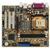
USBPWR_12 KBPWR VGA SEC_IDE PRI_ IDE USB12 Bottom: Top: USB34 RJ-45 USBPWR_34 ATX12V1 Top:Line In Center:Line Out Below:Mic In Intel 82845GE Memory Controller Hub FP_AUDIO Accelerated Graphics Port (AGP) R RTL8100C PCI1 P4GE-MX PCI2 Intel 82801DB ICH4 3Mbit Firmware Hub Audio Codec - Asus P4GE-MX | P4GE-MX User Manual E1722 English Edition - Page 17
1.5.2 Placement direction When installing the motherboard, make sure that you place it into the by circles to secure the motherboard to the chassis. Do not overtighten the screws! Doing so may damage the motherboard. Place this side towards the rear of the chassis ASUS P4GE-MX motherboard 1-7 - Asus P4GE-MX | P4GE-MX User Manual E1722 English Edition - Page 18
match a specific corner on the socket to ensure correct installation. Gold Arrow ® P4GE-MX P4GE-MX CPU Socket 478 Incorrect installation of the CPU into the socket may bend the pins and severely damage the CPU! Notes on Intel® Hyper-Threading Technology 1. This motherboard supports Intel® Pentium - Asus P4GE-MX | P4GE-MX User Manual E1722 English Edition - Page 19
CPU fits only in one correct orientation. DO NOT force the CPU into the socket to prevent bending the pins and damaging the CPU! 5. When the CPU is in place, push down the socket lever to secure the CPU. The lever clicks on the side tab to indicate that it is locked. ASUS P4GE-MX motherboard 1-9 - Asus P4GE-MX | P4GE-MX User Manual E1722 English Edition - Page 20
1.7 System memory 1.7.1 DIMM sockets location You can install 64MB, 256MB, 512MB, and 1GB DDR DIMMs into the DIMM sockets of this motherboard. The following figure illustrates the location of the DDR DIMM sockets. 80 Pins ® P4GE-MX 104 Pins P4GE-MX 184-Pin DDR DIMM Sockets Make sure to unplug - Asus P4GE-MX | P4GE-MX User Manual E1722 English Edition - Page 21
- - Onboard VGA shared When using PCI cards on shared slots, ensure that the drivers support "Share IRQ" or that the cards do not need IRQ assignments. Otherwise, conflicts will arise between the two PCI groups, making the system unstable and the card inoperable. ASUS P4GE-MX motherboard 1-11 - Asus P4GE-MX | P4GE-MX User Manual E1722 English Edition - Page 22
Accelerated Graphics Port (AGP) slot supports AGP 4X (+1.5V) cards. When you buy an AGP card, make sure that you ask for one with +1.5V specification. Note the notches on the card golden fingers to ensure that they fit the AGP slot on the motherboard. Install only +1.5V AGP cards. ® P4GE-MX Keyed - Asus P4GE-MX | P4GE-MX User Manual E1722 English Edition - Page 23
Real Time Clock (RTC) RAM in CMOS. You can clear the CMOS memory of date, time, and system setup parameters by erasing the CMOS RTC RAM CPU Parameter Recall) feature. Shut down and reboot the system so BIOS can automatically reset parameter settings to its previous values. ASUS P4GE-MX motherboard - Asus P4GE-MX | P4GE-MX User Manual E1722 English Edition - Page 24
a corresponding setting in the BIOS. ® P4GE-MX KBPWR 2 1 +5V (Default) 3 2 +5VSB P4GE-MX Keyboard power setting 3. USB CPU, DRAM in slow refresh, power supply in reduced power mode). USBPWR_12 3 2 2 1 +5V (Default) +5VSB USBPWR_34 3 2 2 1 +5V (Default) +5VSB ® P4GE-MX P4GE-MX - Asus P4GE-MX | P4GE-MX User Manual E1722 English Edition - Page 25
(USB) ports are available for connecting USB 2.0 devices. 9. VGA port. This port connects to a VGA monitor. 10. Serial connector. This port connects to your serial mouse and other serial devices. 11. PS/2 keyboard port. This purple connector is for a PS/2 keyboard. ASUS P4GE-MX motherboard 1-15 - Asus P4GE-MX | P4GE-MX User Manual E1722 English Edition - Page 26
(usually zigzag) on the IDE ribbon cable to PIN 1. P4GE-MX IDE connectors PIN 1 2. Floppy disk drive connector (34-1 pin FLOPPY1) This connector supports the provided floppy drive ribbon cable. After connecting one end to the motherboard, connect the other end to the floppy drive. (Pin 5 is - Asus P4GE-MX | P4GE-MX User Manual E1722 English Edition - Page 27
you to receive stereo audio input from sound sources such as a CD-ROM, TV tuner, or MPEG card. Left Audio Channel Ground Ground Right Audio Channel Left Audio Channel Ground Ground Right Audio Channel ® P4GE-MX CD(Black) AUX(White) P4GE-MX Internal audio connectors ASUS P4GE-MX motherboard 1-17 - Asus P4GE-MX | P4GE-MX User Manual E1722 English Edition - Page 28
such as high resolution cameras, scanners, and printers. USB+5V LDM5 LDP5 GND NC ® P4GE-MX P4GE-MX USB 2.0 connector USB56 1 USB+5V LDM6 LDP6 GND • The USB 2.0 module is purchased separately. • Install the USB 2.0 driver before using the USB 2.0 feature. 1-18 Chapter 1: Product introduction - Asus P4GE-MX | P4GE-MX User Manual E1722 English Edition - Page 29
the front panel audio cable. AGND +5VA BLINE_OUT_R BLINE_OUT_L ® P4GE-MX FP_AUDIO MIC2 MICPWR Line out_R NC Line out_L P4GE-MX Front panel audio connector 8. Chassis . CHASSIS +5VSB_MB Chassis Signal GND ® P4GE-MX (Default) P4GE-MX Chassis intrusion connector ASUS P4GE-MX motherboard 1-19 - Asus P4GE-MX | P4GE-MX User Manual E1722 English Edition - Page 30
pin SPDIF_OUT) This connector is for the S/PDIF audio module to allow digital sound output. Connect one end of the S/PDIF audio cable to this connector and the other end to the S/PDIF module. +5V SPDIFOUT GND ® P4GE-MX SPDIF_OUT P4GE-MX Digital audio connector The S/PDIF out module is purchased - Asus P4GE-MX | P4GE-MX User Manual E1722 English Edition - Page 31
cable to this connector and install the bracket on an available slot in the rear panel of the chassis. ® P4GE-MX PIN 1 COM2 P4GE-MX Serial port connector The COM2 up when you turn on the system power. ® P4GE-MX P4GE-MX PLED setting PLED+ NC PLED- PLED1 1 ASUS P4GE-MX motherboard 1-21 - Asus P4GE-MX | P4GE-MX User Manual E1722 English Edition - Page 32
GND IDE_LED+ IDE_LED- Ground Reset NC ® P4GE-MX F_PANEL IDE_LED Reset P4GE-MX Front panel audio connector • System Power LED Lead (2-pin PLED the system between ON and SLEEP, or ON and SOFT OFF, depending on the BIOS or OS settings. Pressing the power switch while in the ON mode for more than - Asus P4GE-MX | P4GE-MX User Manual E1722 English Edition - Page 33
Chapter 2 This chapter tells how to change system settings through the BIOS Setup menus. Detailed descriptions of the BIOS parameters are also provided. BIOS information ASUS P4GE-MX motherboard 2-1 - Asus P4GE-MX | P4GE-MX User Manual E1722 English Edition - Page 34
the original motherboard BIOS using the ASUS Update or AFLASH utilities. • A working BIOS file for this motherboard is in the support CD. Use this file only when you do not have a copy of the original motherboard BIOS file in a floppy disk. • Visit the ASUS website and download the latest BIOS file - Asus P4GE-MX | P4GE-MX User Manual E1722 English Edition - Page 35
the bootable floppy disk you created earlier. 2. Insert the disk that contains the new BIOS file into the floppy drive. 3. Reboot the computer. 4. Press during POST to display the following screen. 5. AWDFLASH checks the new BIOS file from the floppy disk. ASUS P4GE-MX motherboard 2-3 - Asus P4GE-MX | P4GE-MX User Manual E1722 English Edition - Page 36
3. Insert a floppy disk that contains the original or the latest BIOS file for this motherboard. If all the necessary files are found in the floppy disk, the BIOS update process continues. Make sure that the BIOS file in the floppy disk is renamed as "P4GE-MX.ROM". 2-4 Chapter 2: BIOS information - Asus P4GE-MX | P4GE-MX User Manual E1722 English Edition - Page 37
while updating the BIOS! Doing so may cause system boot failure! 2. When the BIOS update process is complete, reboot the system. The recovered BIOS may not be the latest BIOS version for this motherboard. Visit ASUS website (www.asus.com) to download the latest BIOS file. ASUS P4GE-MX motherboard - Asus P4GE-MX | P4GE-MX User Manual E1722 English Edition - Page 38
to update the motherboard BIOS in Windows® environment. This utility is available in the support CD that comes with the motherboard package. ASUS Update requires an Internet connection either through a network or an Internet Service Provider (ISP). To install ASUS Update: 1. Insert the support CD - Asus P4GE-MX | P4GE-MX User Manual E1722 English Edition - Page 39
on the succeeding screens to complete the update process. If you selected the option to update the BIOS from a file, a window pops up prompting you to locate the file. Select the file, click Save, then follow the screen instructions to complete the update process. ASUS P4GE-MX motherboard 2-7 - Asus P4GE-MX | P4GE-MX User Manual E1722 English Edition - Page 40
Setup program This motherboard supports a programmable firmware hub (FHW) chip that you can update using the provided utility described in section "2.1 Managing and updating your BIOS." Use the BIOS Setup program when you are installing a motherboard, reconfiguring your system, or prompted to "Run - Asus P4GE-MX | P4GE-MX User Manual E1722 English Edition - Page 41
the keyboard until the desired item is highlighted. • The BIOS setup screens shown in this chapter are for reference purposes only, and may not exactly match what you see on your screen. • Visit the ASUS website (www.asus.com) to download the latest BIOS information. ASUS P4GE-MX motherboard 2-9 - Asus P4GE-MX | P4GE-MX User Manual E1722 English Edition - Page 42
functions. Navigation Key Function Displays the General Help screen Navigates the Item Specific Help screen Loads previous To display the sub-menu, select the item and press Enter. 2.2.6 Pop-up window Select an item in the menu, then press Enter to display a pop-up window with - Asus P4GE-MX | P4GE-MX User Manual E1722 English Edition - Page 43
field requires users to enter the password before entering the BIOS setup or the system. Select [Setup] to require the password before entering the BIOS Setup. Select [System] to require the password before entering the system. Configuration options: [Setup] [System] ASUS P4GE-MX motherboard 2-11 - Asus P4GE-MX | P4GE-MX User Manual E1722 English Edition - Page 44
BIOS Setup installed. Configuration options: [None] [360K, 5.25 in.] [1.2M , 5.25 in.] [720K , 3.5 in.] [1.44M, 3.5 in.] [2.88M, 3.5 in.] Floppy 3 Mode Support [Disabled] Disables or sets the floppy 3 mode support. Configuration options: [Disabled] [Drive A] Video [EGA/VGA] Selects the type of video - Asus P4GE-MX | P4GE-MX User Manual E1722 English Edition - Page 45
the setup BIOS may detect incorrect parameters. In these cases, select [Manual] to manually enter the IDE hard disk drive parameters. If no drive is installed or if to display a pop-up menu. Type in the value from the drive documentation, then press . ASUS P4GE-MX motherboard 2-13 - Asus P4GE-MX | P4GE-MX User Manual E1722 English Edition - Page 46
the system to fail to recognize the installed hard disk. Capacity [xxxxx MB] This item displays the auto-detected hard disk capacity. The the number of sectors per track. After entering the IDE hard disk drive information into BIOS, use a disk utility, such as FDISK, to partition and format new IDE - Asus P4GE-MX | P4GE-MX User Manual E1722 English Edition - Page 47
SPD] Sets the DRAM Timing configuration. Set to manual if you want to configure each item on your own. Configuration options: [Manual] [By SPD] CAS Latency Time [1.5] Sets the the number of DRAM clocks used for the DRAM parameters. Configuration options: [7] [6] [5] ASUS P4GE-MX motherboard 2-15 - Asus P4GE-MX | P4GE-MX User Manual E1722 English Edition - Page 48
. CPU Clock [100MHz] This item allows you to set the CPU frequency. To do so, highlight the item then press to display a pop-up menu. Enter a value from the specified range, then press Enter. The configuration option values depend on the CPU installed. 2-16 Chapter 2: BIOS information - Asus P4GE-MX | P4GE-MX User Manual E1722 English Edition - Page 49
limit the CPUID maximum value. Set this item to Disabled, if you installed Windows® XP operating system. 2.4.2 Integrated Peripherals IDE DMA Transfer Access [Enabled] Disables or IDE devices. Configuration options: [Auto] [Mode 0] [Mode 1] [Mode 2] [Mode 3] [Mode 4] ASUS P4GE-MX motherboard 2-17 - Asus P4GE-MX | P4GE-MX User Manual E1722 English Edition - Page 50
Support [Enabled] Disables or enables the USB mouse support. Configuration options: [Disabled] [Enabled] AC97 Audio [Auto] Disables or set to auto-detect if there are any AC'97-compliant devices installed. options: [Disabled] [378/IRQ7] [278/IRQ5] [3BC/IRQ7] 2-18 Chapter 2: BIOS information - Asus P4GE-MX | P4GE-MX User Manual E1722 English Edition - Page 51
[Enabled] Allows you to enable or disable the onboard LAN controller. options: [Disabled] [Enabled] Configuration Onboard LAN Boot ROM [Disabled] Allows you to enable or disable the boot ROM of the onboard LAN chip. Configuration options: [Disabled] [Enabled] ASUS P4GE-MX motherboard 2-19 - Asus P4GE-MX | P4GE-MX User Manual E1722 English Edition - Page 52
clear the password, select the KB Power On Password then press password. The message "PASSWORD DISABLED!!! Press any key to continue..." appears. 2-20 Chapter 2: BIOS information - Asus P4GE-MX | P4GE-MX User Manual E1722 English Edition - Page 53
Month) Alarm and Time(hh:mm:ss) Alarm fields are activated for manual setup. Configuration options: [Enabled] [Disabled] Date (of Month) Alarm [0] To press to display a pop-up menu for the hour field. 2. Key-in a value (Min=0, Max=23), then press . ASUS P4GE-MX motherboard 2-21 - Asus P4GE-MX | P4GE-MX User Manual E1722 English Edition - Page 54
[56ºC/133ºF] [60ºC/140ºF] [63ºC/145ºF] [66ºC/151ºF] [70ºC/158ºF] MB Temperature [xxxºC] CPU Temperature [xxxºC] The onboard hardware monitor automatically detects and displays the motherboard and CPU temperatures. CPU Fan Speed [xxxxRPM] or [0RPM] Chassis Fan Speed [xxxxRPM] or [0RPM] The onboard - Asus P4GE-MX | P4GE-MX User Manual E1722 English Edition - Page 55
[USB-CDROM] [USB-HDD] [LAN] [Disabled] Boot Other Device [Enabled When enabled, the BIOS will seek the display feature. Configuration options: [Disabled] [Enabled] Make sure that the Full Screen Logo Show item is set to [Enabled] if you wish to use the ASUS MyLogo™ feature. ASUS P4GE-MX motherboard - Asus P4GE-MX | P4GE-MX User Manual E1722 English Edition - Page 56
for a confirmation before you exit the BIOS Setup. Load Fail-Safe Defaults This option allows you to load the fail-safe values for each of the parameters on the Setup menus. When you select this option or if you press , a confirmation window appears. Press to load fail-safe values. Select - Asus P4GE-MX | P4GE-MX User Manual E1722 English Edition - Page 57
Chapter 3 This chapter describes the contents of the support CD that comes with the motherboard package. Software support - Asus P4GE-MX | P4GE-MX User Manual E1722 English Edition - Page 58
an operating system This motherboard supports Windows® 98SE/ME/2000/XP operating system (OS). Always install the latest OS version and corresponding updates to maximize the features of your hardware. Motherboard settings and hardware options vary, so use the setup procedures presented in this - Asus P4GE-MX | P4GE-MX User Manual E1722 English Edition - Page 59
driver. REALTEK LAN Driver This item installs the Realtek® LAN driver. For Windows® XP users, make sure to install Windows® XP Service Pack 1 to support USB 2.0. 3.2.3 Utilities menu The Utilities menu shows the applications and other software that the motherboard supports. ASUS P4GE-MX motherboard - Asus P4GE-MX | P4GE-MX User Manual E1722 English Edition - Page 60
speed, CPU temperature, and system voltages, and alerts you on any detected problems. This utility helps you keep your computer at a healthy operating condition. Install ASUS Update This program allows you to download the latest version of the BIOS from the ASUS website. Before using the ASUS Update - Asus P4GE-MX | P4GE-MX User Manual E1722 English Edition - Page 61
feature The connector sensing feature allows you to check if your audio devices are connected properly. Click the the Connector Sensing tab to display the details. Click the Option button to change sensing options. Click the Start button to start connection sensing. ASUS P4GE-MX motherboard 3-5 - Asus P4GE-MX | P4GE-MX User Manual E1722 English Edition - Page 62
problems, make sure that your audio cables are connected to the proper audio jack and repeat connector sensing. Click the X button to exit EZ-connection dialog box. Click the Exit (X) button on the upper-right hand corner of the window to exit audio control panel. 3-6 Chapter 3: Software support
-
 1
1 -
 2
2 -
 3
3 -
 4
4 -
 5
5 -
 6
6 -
 7
7 -
8
-
9
-
10
-
11
-
12
-
13
-
14
-
15
-
16
-
17
-
18
-
19
-
20
-
21
-
22
-
23
-
24
-
25
-
26
-
27
-
28
-
29
-
30
-
31
-
32
-
33
-
34
-
35
-
36
-
37
-
38
-
39
-
40
-
41
-
42
-
43
-
44
-
45
-
46
-
47
-
48
-
49
-
50
-
51
-
52
-
53
-
54
-
55
-
56
-
57
-
58
-
59
-
60
-
61
-
62
 |
 |

Motherboard
P4GE-MX
User Guide