Asus P4GE-V P4GE-V User Manual
Asus P4GE-V Manual
 |
View all Asus P4GE-V manuals
Add to My Manuals
Save this manual to your list of manuals |
Asus P4GE-V manual content summary:
- Asus P4GE-V | P4GE-V User Manual - Page 1
Motherboard P4GE-V User Guide - Asus P4GE-V | P4GE-V User Manual - Page 2
Product warranty or service will not be extended if: (1) the product is repaired, modified or altered, unless such repair, modification of alteration is authorized in writing by ASUS; or (2) the serial number of the product is defaced or missing. ASUS PROVIDES THIS MANUAL "AS IS" WITHOUT WARRANTY - Asus P4GE-V | P4GE-V User Manual - Page 3
this guide viii How this guide is organized viii Conventions used in this guide ix Where to find more information ix ASUS contact information x P4GE-V specifications summary xi Chapter 1: Product introduction 1.1 Welcome 1-1 1.2 Package contents 1-1 1.3 Special features 1-2 1.4 Motherboard - Asus P4GE-V | P4GE-V User Manual - Page 4
POST Messages 3-2 3.3 Powering off the computer 3-4 Chapter 4: BIOS setup 4.1 Managing and updating your BIOS 4-1 4.1.1 Using ASUS EZ Flash to update the BIOS 4-1 4.1.2 Using AFLASH to update the BIOS 4-3 4.2 BIOS Setup program 4-7 4.2.1 BIOS menu bar 4-8 4.2.2 Legend bar 4-8 4.3 Main Menu - Asus P4GE-V | P4GE-V User Manual - Page 5
the support CD 5-1 5.2.2 Drivers menu 5-2 5.2.3 Utilities menu 5-5 5.2.4 ASUS Contact Information 5-6 5.2.5 Other information 5-7 5.3 Software information 5-9 5.3.1 ASUS Update 5-9 5.3.2 ASUS MyLogo2 5-10 5.3.3 ASUS PC Probe 5-12 5.3.4 Winbond Voice Editor 5-17 5.3.5 Multi-channel audio - Asus P4GE-V | P4GE-V User Manual - Page 6
and, if not installed and used in accordance with manufacturer's instructions, may cause harmful interference to radio communications. However, there is reception, which can be determined by turning the equipment off and on, the user is encouraged to try to correct the interference by one or more of - Asus P4GE-V | P4GE-V User Manual - Page 7
Contact a qualified service technician or your retailer. Operation safety • Before installing the motherboard and adding devices on it, carefully read all the manuals that came with . • If you encounter technical problems with the product, contact a qualified service technician or your retailer. vii - Asus P4GE-V | P4GE-V User Manual - Page 8
About this guide This user guide contains the information you need when installing the ASUS P4GE-V motherboard. How this guide is organized This manual contains the following parts: • Chapter 1: Product introduction This chapter describes the features of the P4GE-V motherboard. It includes brief - Asus P4GE-V | P4GE-V User Manual - Page 9
this guide To make sure that you perform certain tasks properly, take note of the following symbols used throughout this manual. WARNING updates. 1. ASUS Websites The ASUS websites worldwide provide updated information on ASUS hardware and software products. The ASUS websites are listed in the ASUS - Asus P4GE-V | P4GE-V User Manual - Page 10
CA 94560, USA General Fax: +1-510-608-4555 General Email: [email protected] Technical Support Support Fax: +1-510-608-4555 General Support: +1-502-933-8713 Web Site: www.asus.com Support Email: [email protected] ASUS COMPUTER GmbH (Europe) Address: Harkortstr. 25, 40880 Ratingen, BRD, Germany - Asus P4GE-V | P4GE-V User Manual - Page 11
AD1980 6-channel audio CODEC Broadcom® BCM4401 Fast Ethernet controller ASUS JumperFree™ mode ASUS POST Reporter™ ASUS EZ Plug™ ASUS Q-Fan ASUS EZ Flash C.P.R. (CPU Parameter Recall) CrashFree BIOS Power Loss Restart SFS (Stepless Frequency Selection) CPU throttle Adjustable CPU VCORE, memory, and - Asus P4GE-V | P4GE-V User Manual - Page 12
MIDI connector S/PDIF Out connector CD/AUX/Modem audio connectors Front panel audio connector 4Mb Flash ROM, Award BIOS, TCAV, PnP, DMI2.0, WfM2.0, SM BIOS2.3, Multi-language BIOS, ASUS EZ Flash, CrashFree BIOS, C.P.R. (CPU Parameter Recall) PCI 2.2, USB 2.0 WfM 2.0. DMI 2.0, WOL/WOR by PME, chassis - Asus P4GE-V | P4GE-V User Manual - Page 13
Chapter 1 This chapter describes the features of the P4GE-V motherboard. It includes brief explanations of the special attributes of the motherboard and the new technology it supports. Product introduction - Asus P4GE-V | P4GE-V User Manual - Page 14
Chapter summary 1.1 Welcome 1-1 1.2 Package contents 1-1 1.3 Special features 1-2 1.4 Motherboard overview 1-6 ASUS P4GE-V motherboard - Asus P4GE-V | P4GE-V User Manual - Page 15
. Supporting up to 2GB of system memory with PC2700/2100/1600 DDR SDRAM, high-resolution graphics via an AGP 4X slot, USB 2.0, 3D video, and 6-channel audio features, the P4GE-V is your perfect vehicle to get ahead in the world of power computing! Before you start installing the motherboard, and - Asus P4GE-V | P4GE-V User Manual - Page 16
333MHz memory bus delivers the required bandwidth for the latest 3D graphics, multimedia, and Internet applications. See page 2-10. Onboard LAN solution (on LAN models only) The motherboard mounts the BroadCom® BCM4401 chipset to support 10BASE-T/100BASE-TX networking protocol. USB 2.0 technology - Asus P4GE-V | P4GE-V User Manual - Page 17
Memory Controller Hub (GMCH) has an integrated graphics controller that delivers 3D, 2D, and video capabilities. The GMCH video engines support video conferencing and other video messages, and provides multi-language support. See pages 3-1, 4-25, and 5-17. ASUS P4GE-V motherboard user guide 1-3 - Asus P4GE-V | P4GE-V User Manual - Page 18
menus allow you to configure easier and faster. Visit the ASUS website for information on the supported languages. See page 4-11. ASUS EZ Flash BIOS With the ASUS EZ Flash, you can easily update the system BIOS even before loading the operating system. No need to use a DOS-based utility or boot from - Asus P4GE-V | P4GE-V User Manual - Page 19
systems that support OS Direct Power Management (OSPM). See page 4-30. Chassis intrusion detection The motherboard supports chassis intrusion monitoring through the ASUS ASIC. A chassis intrusion event is retained in CMOS for more protection. See page 2-20. ASUS P4GE-V motherboard user guide 1-5 - Asus P4GE-V | P4GE-V User Manual - Page 20
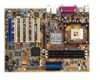
. 1.4.1 Major components The following are the major components of the P4GE-V motherboard as pointed out in the picture on page 1-7. 1. ATX 12V connector 2. CPU socket 3. North Bridge controller 4. DDR DIMM sockets 5. ASUS EZ Plug™ 12V connector 6. ATX power connector 7. Floppy disk connector - Asus P4GE-V | P4GE-V User Manual - Page 21
1 23 4 5 6 7 8 19 18 17 9 16 15 10 20 30 29 14 13 12 11 21 22 23 24 25 28 27 26 ASUS P4GE-V motherboard user guide 1-7 - Asus P4GE-V | P4GE-V User Manual - Page 22
12V plug from the ATX 12V power supply. 2 CPU socket. A 478-pin surface mount, Zero Insertion support up to 2GB system memory using unbuffered non-ECC PC2700/ PC2100/PC1600 DDR DIMMs. 5 ASUS EZ Plug™ +12V connector. This ASUS bus master IDE controller, up to six USB 2.0/1.1 ports, I/O APIC, SMBus 2.0 - Asus P4GE-V | P4GE-V User Manual - Page 23
. 21 Parallel port. This 25-pin port connects a parallel printer, a scanner, or other devices. 22 RJ-45 port. This port allows connection to a Local Area Network (LAN) through a network hub. (on LAN models only) ASUS P4GE-V motherboard user guide 1-9 - Asus P4GE-V | P4GE-V User Manual - Page 24
Line In (light blue) jack connects a tape player or other audio sources. In 6-channel mode, the function of this jack becomes Bass Rear Speaker Out. 26 USB 2.0 ports 3 and 4. These two 4-pin Universal Serial Bus (USB) ports are available for connecting USB 2.0 devices. 27 Video port. This port is - Asus P4GE-V | P4GE-V User Manual - Page 25
Chapter 2 This chapter describes the hardware setup procedures that you have to perform when installing system components. It includes details on the switches, jumpers, and connectors on the motherboard. Hardware information - Asus P4GE-V | P4GE-V User Manual - Page 26
Chapter summary 2.1 Motherboard installation 2-1 2.2 Motherboard layout 2-2 2.3 Before you proceed 2-3 2.4 Central Processing Unit (CPU 2-4 2.5 System memory 2-10 2.6 Expansion slots 2-13 2.7 Jumpers 2-16 2.8 Connectors 2-18 ASUS P4GE-V motherboard - Asus P4GE-V | P4GE-V User Manual - Page 27
in the image below. 2.1.2 Screw holes Place seven (7) screws into the holes indicated by circles to secure the motherboard to the chassis. Do not overtighten the screws! Doing so may damage the motherboard. Place this side towards the rear of the chassis ASUS P4GE-V motherboard user guide 2-1 - Asus P4GE-V | P4GE-V User Manual - Page 28
PCI5 TRPWR1 ASUS ASIC with Hardware Monitor Super I/O IDE_LED1 FP_AUDIO1 PCI6 / BlueMagic PCI Slot WPCI_USB USB_56 SB_PWR1 CHASSIS1 IR_CON1 GAME1 COM2 4Mbit Firmware Hub SMB1 PANEL1 The audio and LAN features are optional. These components are grayed out in the above motherboard layout - Asus P4GE-V | P4GE-V User Manual - Page 29
AGP slot, this LED lights up thus preventing the system to power up. This LED remains off if you plug in a 1.5V AGP card. AGP_WARN1 ® P4GE-V P4GE-V Onboard LED ON Incorrect AGP Card OFF Correct AGP Card SB_PWR1 ON Standby Power OFF Powered Off ASUS P4GE-V motherboard user guide 2-3 - Asus P4GE-V | P4GE-V User Manual - Page 30
execution of integer instructions, and data transfer rates of 3.2GB/s and 4.2GB/s. Note in the illustration that the CPU has a gold on this motherboard: 1. Buy an Intel Pentium 4 CPU that supports Hyper-Threading technology. Install the CPU. 2. Power up the system and enter BIOS Setup (see - Asus P4GE-V | P4GE-V User Manual - Page 31
-pin ZIF socket on the motherboard. 2. Unlock the socket by pressing the lever sideways, then lift it up to a 90°-100° angle. Socket Lever 90 - 100 Make sure that the socket lever is lifted up to 90°-100° angle, otherwise the CPU does not fit in completely. ASUS P4GE-V motherboard user guide 2-5 - Asus P4GE-V | P4GE-V User Manual - Page 32
base of the socket lever. 4. Carefully insert the CPU into the socket until it fits in place. The CPU fits only in one correct orientation. DO NOT force the CPU into the socket to prevent bending the pins and damaging the CPU! Gold Mark 5. When the CPU is in place, push down the socket lever - Asus P4GE-V | P4GE-V User Manual - Page 33
Retention Module Base Your boxed Intel Pentium 4 Processor package should come with installation instructions for the CPU, heatsink, and the retention mechanism. If the instructions in this section do not match the CPU documentation, follow the latter. ASUS P4GE-V motherboard user guide 2-7 - Asus P4GE-V | P4GE-V User Manual - Page 34
2. Position the fan with the retention mechanism on top of the heatsink. Align and snap the four hooks of the retention mechanism to the holes on each corner of the module base. Make sure that the fan and retention mechanism assembly perfectly fits the heatsink and module base, otherwise you cannot - Asus P4GE-V | P4GE-V User Manual - Page 35
mechanism are in place, connect the CPU fan cable to the connector on the motherboard labeled CPU_FAN1. CPU Fan Connector (CPU_FAN1) Don't forget to connect the CPU fan connector! Hardware monitoring errors may occur if you fail to plug this connector. ASUS P4GE-V motherboard user guide 2-9 - Asus P4GE-V | P4GE-V User Manual - Page 36
184-pin unbuffered non-ECC PC2700/PC2100/ PC1600 DDR DIMMs. ® P4GE-V 80 Pins 104 Pins P4GE-V 184-Pin DDR DIMM Sockets This motherboard supports different memory frequencies depending on the CPU FSB (Front Side Bus) and the type of DDR DIMM. CPU FSB 533 MHz 400 MHz DDR DIMM Type PC2700 PC2100 - Asus P4GE-V | P4GE-V User Manual - Page 37
2.5.2 Memory configurations You may install any DDR DIMMs with 64MB, 128MB, 256MB, 512MB, and 1GB densities into the DIMM sockets. at the same time but neither one can be x16 DDR module. 3. Double-sided x16 DDR DIMMs are not supported on this motherboard. ASUS P4GE-V motherboard user guide 2-11 - Asus P4GE-V | P4GE-V User Manual - Page 38
components. Failure to do so may cause severe damage to both the motherboard and the components. Follow these steps to install a DIMM. 1. Unlock 1. Simultaneously press the retaining clips outward to unlock the DIMM. Support the DIMM lightly with your fingers when pressing the retaining clips. - Asus P4GE-V | P4GE-V User Manual - Page 39
software settings. 1. Turn on the system and change the necessary BIOS settings, if any. See Chapter 4 for information on BIOS setup. 2. Assign an IRQ to the card. Refer to the tables on the next page. 3. Install the software drivers for the expansion card. ASUS P4GE-V motherboard user guide 2-13 - Asus P4GE-V | P4GE-V User Manual - Page 40
9* 4 ACPI Mode when for this motherboard AB PCI USB controller HC0 shared - Onboard USB controller HC1 - - Onboard USB controller HC2 - - Onboard USB 2.0 controller - - Onboard LAN When using PCI cards on shared slots, ensure that the drivers support "Share IRQ" or that the cards do not need - Asus P4GE-V | P4GE-V User Manual - Page 41
as this LED is lighted, you cannot turn on the system power even if you press the power button, thus preventing permanent damage to the motherboard. Install only 1.5V AGP cards on this motherboard! ® P4GE-V P4GE-V Accelerated Graphics Port (AGP) ASUS P4GE-V motherboard user guide 2-15 - Asus P4GE-V | P4GE-V User Manual - Page 42
supply at least 1A on the +5VSB lead, and a corresponding setting in the BIOS (see section 4.5.1 Power Up Control). KBPWR1 12 23 P4GE-V +5V +5VSB ® (Default) P4GE-V Keyboard Power Setting 2. Wireless PCI and USB settings (3-pin WPCI_USB) These jumpers are reserved. DO NOT change the default - Asus P4GE-V | P4GE-V User Manual - Page 43
Real Time Clock (RTC) RAM in CMOS. You can clear the CMOS memory of date, time, and system setup parameters by erasing the CMOS RTC CPU Parameter Recall) feature. Shut down and reboot the system so BIOS can automatically reset parameter settings to default values. ASUS P4GE-V motherboard user guide - Asus P4GE-V | P4GE-V User Manual - Page 44
not ® light up, try reversing the 2-pin plug. P4GE-V IDE_LED1 P4GE-V HD Activity LED 2. Floppy disk drive connector (34-1 pin FLOPPY1) This connector supports the provided floppy drive ribbon cable. After connecting one end to the motherboard, connect the other end to the floppy drive. (Pin - Asus P4GE-V | P4GE-V User Manual - Page 45
for the jumper settings. BIOS supports specific device bootup. If you P4GE-V IDE Connectors PIN 1 PIN 1 For UltraDMA/100/66 IDE devices, use an 80-conductor IDE cable. The UltraDMA/66 cable included in the motherboard package also supports UltraDMA/100. ASUS P4GE-V motherboard user guide - Asus P4GE-V | P4GE-V User Manual - Page 46
you wish to use the chassis intrusion detection feature, remove the jumper cap from the pins. CHASSIS1 +5VSB_MB Chassis Signal GND ® P4GE-V P4GE-V Chassis Alarm Lead (Default) 5. SMBus connector (6-1 pin SMB1) This connector allows you to connect SMBus (System Management Bus) devices. Devices - Asus P4GE-V | P4GE-V User Manual - Page 47
P4GE-V ATXPWR1 EZ_PLUG1 Pin 1 +12.0VDC +5VSB PWR_OK GND +5.0VDC GND +5.0VDC GND +3.3VDC +3.3VDC +5.0VDC +5.0VDC -5.0VDC +12V GND GND +5V GND GND GND PS_ON# GND ATX12V1 -12.0VDC +3.3VDC +12V DC +12V DC GND GND P4GE-V ATX & Auxiliary Power Connectors ASUS P4GE-V motherboard user guide - Asus P4GE-V | P4GE-V User Manual - Page 48
7. CPU, Chassis, and Power Fan Connectors (3-pin CPU_FAN1, PWR_FAN1, CHA_FAN1) The fan connectors support cooling fans of 350mA~740mA (8.88W max.) or a total of 1A~2.22A (26.64W max.) at +12V. Connect the fan cables to the fan connectors on the motherboard, making sure that the black wire of each - Asus P4GE-V | P4GE-V User Manual - Page 49
that support the next generation USB peripherals such as high resolution cameras, scanners, and printers. You must install the driver before you can use the USB 2.0 capability. USB+5V LP5LP5+ GND NC ® P4GE-V P4GE-V USB 2.0 Header USB_56 1 USB+5V LP4LP4+ GND ASUS P4GE-V motherboard user guide - Asus P4GE-V | P4GE-V User Manual - Page 50
connector supports a GAME/MIDI module. If your package came with the optional USB 2.0/GAME module, connect the GAME/MIDI cable to this connector. The GAME/MIDI port on the module connects a joystick or a game pad for playing games, and MIDI devices for playing or editing audio files. ® P4GE-V +5V - Asus P4GE-V | P4GE-V User Manual - Page 51
mounts to a small opening on system chassis that support this feature. You must also configure the UART2 Use As parameter in BIOS to set UART2 for use with IR. See section at the back of the system chassis. COM2 PIN 1 ® P4GE-V P4GE-V Serial COM2 Bracket ASUS P4GE-V motherboard user guide 2-25 - Asus P4GE-V | P4GE-V User Manual - Page 52
analog sound output. Connect one end of the audio cable to the S/PDIF Out connector on the motherboard, and the other end to the S/PDIF module. SPDIF_OUT1 ® P4GE-V P4GE-V Digital Audio Connector 15. Front panel audio connector (10-1 pin FP_AUDIO1) (on audio models only) This is an interface for the - Asus P4GE-V | P4GE-V User Manual - Page 53
and warnings. • System Management Interrupt Lead (2-pin SMI) This 2-pin connector allows you to manually place the system into a suspend mode, or "green" mode, where system activity is instantly for rebooting the system without turning off the system power. ASUS P4GE-V motherboard user guide 2-27 - Asus P4GE-V | P4GE-V User Manual - Page 54
2-28 Chapter 2: Hardware information - Asus P4GE-V | P4GE-V User Manual - Page 55
Chapter 3 This chapter describes the power up sequence and gives information on the BIOS beep codes. Powering up - Asus P4GE-V | P4GE-V User Manual - Page 56
Chapter summary 3.1 Starting up for the first time 3-1 3.2 Vocal POST Messages 3-2 3.3 Powering off the computer 3-4 ASUS P4GE-V motherboard - Asus P4GE-V | P4GE-V User Manual - Page 57
; System running at a lower frequency You will not hear the BIOS beeps when the ASUS POST Reporter™ is enabled. You will hear the vocal POST messages instead. 7. At power on, hold down to enter BIOS Setup. Follow the instructions in Chapter 4. ASUS P4GE-V motherboard user guide 3-1 - Asus P4GE-V | P4GE-V User Manual - Page 58
. POST Message No CPU installed System failed CPU test System failed memory test System failed VGA test System failed due to CPU over-clocking Action • Install an Intel Pentium 4 Processor into the CPU socket. • Check the CPU if properly installed. • Call ASUS technical support for assistance. See - Asus P4GE-V | P4GE-V User Manual - Page 59
information" on page x. System completed Power-On Self Test • No action required Computer now booting from operating • No action required system You may disable the ASUS POST Reporter™ in the BIOS setup. See section "4.4.2 I/O Device Configuration". ASUS P4GE-V motherboard user guide 3-3 - Asus P4GE-V | P4GE-V User Manual - Page 60
3.3 Powering off the computer You must first exit the operating system and shut down the system before switching off the power. For ATX power supplies, you can press the ATX power switch after exiting or shutting down the operating system. If you use Windows 2000/XP, click the Start button, click - Asus P4GE-V | P4GE-V User Manual - Page 61
Chapter 4 This chapter tells how to change system settings through the BIOS Setup menus. Detailed descriptions of the BIOS parameters are also provided. BIOS setup - Asus P4GE-V | P4GE-V User Manual - Page 62
Chapter summary 4.1 Managing and updating your BIOS 4-1 4.2 BIOS Setup program 4-7 4.3 Main Menu 4-10 4.4 Advanced Menu 4-17 4.5 Power Menu 4-29 4.6 Boot Menu 4-35 4.7 Exit Menu 4-37 ASUS P4GE-V motherboard - Asus P4GE-V | P4GE-V User Manual - Page 63
you see on your screen may not be exactly the same as shown. 4. Insert the disk that contains the new BIOS file into the floppy drive. You will receive the error message, "WARNING! Device not ready." if you proceed to step 5 without the disk in the drive. ASUS P4GE-V motherboard user guide 4-1 - Asus P4GE-V | P4GE-V User Manual - Page 64
that you downloaded from the ASUS website, then press . EZ Flash will automatically access drive A to look for the file name that you typed. When found, the following message appears on screen. [BIOS Information in File] BIOS Version: P4GE-V Boot Block WARNING! Continue to update the BIOS - Asus P4GE-V | P4GE-V User Manual - Page 65
within Windows, and does not work with certain memory drivers that may be loaded when you boot from the Memory:, the memory chip is either not programmable or is not supported by the ACPI BIOS and therefore, cannot be programmed by the Flash Memory Writer utility. ASUS P4GE-V motherboard user guide - Asus P4GE-V | P4GE-V User Manual - Page 66
5. Select 1. Save Current BIOS to File from the Main menu and press . The Save Current BIOS To File screen appears. 6. Type a filename and the path, for example, A:\XXX-XX.XXX, then press . 4-4 Chapter 4: BIOS Setup - Asus P4GE-V | P4GE-V User Manual - Page 67
Boot Block and ESCD screen appears. 5. Type the filename of your new BIOS and the path, for example, A:\XXX-XX.XXX, then press . To cancel this operation, press . 6. When prompted to confirm the BIOS update, press Y to start the update. ASUS P4GE-V motherboard user guide 4-5 - Asus P4GE-V | P4GE-V User Manual - Page 68
process, and if the problem persists, load the original BIOS file you saved to the boot disk. If the Flash Memory Writer utility is not able to successfully update a complete BIOS file, the system may not boot. If this happens, call the ASUS service center for support. 4-6 Chapter 4: BIOS Setup - Asus P4GE-V | P4GE-V User Manual - Page 69
-menus and make your selections among the predetermined choices. Because the BIOS software is constantly being updated, the following BIOS setup screens and descriptions are for reference purposes only, and may not exactly match what you see on your screen. ASUS P4GE-V motherboard user guide 4-7 - Asus P4GE-V | P4GE-V User Manual - Page 70
in the legend bar with their corresponding functions. Navigation Key(s) Function Description or Displays the General Help screen from anywhere in the BIOS Setup Jumps to the Exit menu or returns to the main menu from a sub-menu Left or Right arrow Selects the menu item - Asus P4GE-V | P4GE-V User Manual - Page 71
General help In addition to the Item Specific Help window, the BIOS setup program also provides a General Help screen. You may launch this screen from any menu by simply each menu. This window displays the help text for the currently highlighted field. ASUS P4GE-V motherboard user guide 4-9 - Asus P4GE-V | P4GE-V User Manual - Page 72
. Configuration options: [None] [360K, 5.25 in.] [1.2M , 5.25 in.] [720K , 3.5 in.] [1.44M, 3.5 in.] [2.88M, 3.5 in.] Floppy 3 Mode Support [Disabled] This is required to support older Japanese floppy drives. The Floppy 3 Mode feature allows reading and writing of 1.2MB (as opposed to 1.44MB) on - Asus P4GE-V | P4GE-V User Manual - Page 73
now set to [Enabled]. This password allows full access to the BIOS Setup menus. To clear the password, highlight this field and press Memory [XXX MB] This field automatically displays the amount of conventional memory detected by the system during the boot process. ASUS P4GE-V motherboard user guide - Asus P4GE-V | P4GE-V User Manual - Page 74
already formatted on an older system, Setup may detect incorrect parameters. In these cases, select [User Type HDD] to manually enter the IDE hard disk drive parameters. Refer to the next section for details. Before attempting fail to recognize the installed hard disk. 4-12 Chapter 4: BIOS Setup - Asus P4GE-V | P4GE-V User Manual - Page 75
User Type HDD] Manually enter the number of cylinders, heads and sectors per track for the drive. Refer to the drive documentation or on the drive label for this information. After entering the IDE hard disk drive information into BIOS that you configured. ASUS P4GE-V motherboard user guide 4-13 - Asus P4GE-V | P4GE-V User Manual - Page 76
correct value. To make changes to this field, set the Type field to [User Type HDD] and the Translation Method field to [Manual]. CHS Capacity This field shows the drive's maximum CHS capacity as calculated by the BIOS based on the drive information you entered. Maximum LBA Capacity This field shows - Asus P4GE-V | P4GE-V User Manual - Page 77
drive supports. Note that when this field is automatically configured, the set value may not always be the fastest value for the drive. You may also manually configure Type field to [User Type HDD]. Configuration options: [0] [1] [2] [3] [4] [5] [Disabled] ASUS P4GE-V motherboard user guide 4-15 - Asus P4GE-V | P4GE-V User Manual - Page 78
4.3.2 Keyboard Features Boot Up NumLock Status [On] This field enables users to activate the Number Lock function upon system boot. Configuration options: [Off] [On] displaying the first and second characters. Configuration options: [1/4 Sec] [1/2 Sec] [3/4 Sec] [1 Sec] 4-16 Chapter 4: BIOS Setup - Asus P4GE-V | P4GE-V User Manual - Page 79
item. CPU External Frequency (MHz) (when CPU Speed is set to [Manual]) This feature tells the clock generator what frequency to send to the system bus and PCI bus. The bus frequency (external frequency) multiplied by the bus multiple equals the CPU speed. ASUS P4GE-V motherboard user guide 4-17 - Asus P4GE-V | P4GE-V User Manual - Page 80
Setting [Auto] The [Manual] setting allows you to manually select the core voltage supplied to the CPU (see next item). However, it is recommended that you keep the default setting [Auto] to allow the system to automatically determine the appropriate CPU core voltage. 4-18 Chapter 4: BIOS Setup - Asus P4GE-V | P4GE-V User Manual - Page 81
is detected, the BIOS assigns IRQ12 to the PS/2 mouse. Otherwise, IRQ12 can be used for expansion cards. When you set this field to [Enabled], BIOS reserves IRQ12, whether or not a PS/2 mouse is detected at startup. Configuration options: [Enabled] [Auto] ASUS P4GE-V motherboard user guide 4-19 - Asus P4GE-V | P4GE-V User Manual - Page 82
USB Legacy Support [Auto] This motherboard supports Universal Serial Bus (USB) devices. The default of [Auto] allows the system to detect a USB device at startup. If detected, the USB controller legacy mode is enabled. If not detected, the USB controller legacy mode is disabled. When you set this - Asus P4GE-V | P4GE-V User Manual - Page 83
[Auto] Configuration options: [Auto] [4] [8] Memory Turbo Mode [Disabled] This item allows you to enable or disable the memory turbo mode. Configuration options: [Disabled] [Enabled] DRAM Refresh Rate [By SPD] Configuration options: [By SPD] [15.6us] [7.8us] ASUS P4GE-V motherboard user guide 4-21 - Asus P4GE-V | P4GE-V User Manual - Page 84
[Auto] When set to Auto, this item allows BIOS to automatically detect the onboard VGA, and the AGP Mode appear. You may configure these items separately. Onboard VGA Shared Memory [8 MB] This item allows you to select the size of memory shared to the onboard VGA. Configuration options: [1 MB] [8 MB - Asus P4GE-V | P4GE-V User Manual - Page 85
channels to [Disabled]. Configuration options: [Both] [Primary] [Secondary] [Disabled] USB 2.0 HS Reference Voltage [Medium] This item controls the USB 2.0 high-speed drive strength reference voltage. Configuration options: [Low] [Medium] [High] [Maximum] ASUS P4GE-V motherboard user guide 4-23 - Asus P4GE-V | P4GE-V User Manual - Page 86
you disable this field, the Parallel Port Mode and ECP DMA Select configurations are not available. Configuration options: [Disabled] [378H/IRQ7] [278H/IRQ5] 4-24 Chapter 4: BIOS Setup - Asus P4GE-V | P4GE-V User Manual - Page 87
] [330H-331H] [300H-301H] Speech POST Reporter [Enabled] This field enables or disables the ASUS POST Reporter™ feature. See section "1.3 Special Features" and "3.2 Vocal POST messages" for more information. Configuration options: [Disabled] [Enabled] ASUS P4GE-V motherboard user guide 4-25 - Asus P4GE-V | P4GE-V User Manual - Page 88
graphics accelerators or MPEG video cards, may not show colors properly. Setting this field to [Enabled] corrects this problem. If you are using for best performance and stability. USB 1.1 Controllers [3 Controllers] This field allows you to select the number of USB 1.1 controllers that you wish - Asus P4GE-V | P4GE-V User Manual - Page 89
or disable the onboard LAN controller. Configuration options: [Disabled] [Enabled] Onboard LAN Boot ROM [Disabled] This field allows you to enable or disable the option ROM in the onboard LAN controller chipset. Configuration options: [Disabled] [Enabled] ASUS P4GE-V motherboard user guide 4-27 - Asus P4GE-V | P4GE-V User Manual - Page 90
to [Yes] if you install a legacy ISA card that requires a unique IRQ and you are NOT using ICU. Configuration options: [No/ICU] [Yes] 4-28 Chapter 4: BIOS Setup - Asus P4GE-V | P4GE-V User Manual - Page 91
turns off the video display and shuts down the hard disk after a period of inactivity. Power Management [User Defined] This Advanced Power Management (APM) utility to keep the system time updated even when the computer enters suspend mode. In Windows 3.x and ASUS P4GE-V motherboard user guide 4-29 - Asus P4GE-V | P4GE-V User Manual - Page 92
management. Configuration options: [Always On] [Suspend -> Off] Video Off Method [DPMS OFF] This field defines the video off features. The Display Power Management System (DPMS) feature allows the BIOS to control the video display card if it supports the DPMS feature. [Blank Screen] only blanks the - Asus P4GE-V | P4GE-V User Manual - Page 93
On PCI Card [Disabled] When set to [Enabled], this parameter allows you to turn on the system through a PCI LAN or modem card. This feature requires an ATX power supply that provides at least 1A on the +5VSB lead. Configuration options: [Disabled] [Enabled] ASUS P4GE-V motherboard user guide 4-31 - Asus P4GE-V | P4GE-V User Manual - Page 94
time of the day by selecting [Everyday] or at a certain time and day by selecting [By Date]. Configuration options: [Disabled] [Everyday] [By Date] 4-32 Chapter 4: BIOS Setup - Asus P4GE-V | P4GE-V User Manual - Page 95
the motherboard and CPU temperatures. If your power supply comes with a two-pin thermal sensor cable, connect this cable to the TRPWR connector on the motherboard to allow BIOS to the corresponding response time. Configuration options: [Disabled] [Enabled] ASUS P4GE-V motherboard user guide 4-33 - Asus P4GE-V | P4GE-V User Manual - Page 96
hardware monitor automatically detects and displays the CPU, chassis, and power fan speeds in rotations per minute (RPM). If any of the fans is not connected to the motherboard, the specific field shows N/A. VCORE Voltage "Press F1 to continue or DEL to enter SETUP". 4-34 Chapter 4: BIOS Setup - Asus P4GE-V | P4GE-V User Manual - Page 97
in the boot sequence. Pressing [Enter] will show the product IDs of all your connected ATAPI CD-ROM drives. Other Boot Device Select [INT18 Device (Network)] Configuration options: [Disabled] [SCSI Boot Device] [INT18 Device (Network)] ASUS P4GE-V motherboard user guide 4-35 - Asus P4GE-V | P4GE-V User Manual - Page 98
and-Play (PnP) operating system to configure the PCI bus slots instead of using the BIOS. When [Yes] is selected, interrupts may be reassigned by the OS. If you installed item is set to [Enabled] if you wish to use the ASUS MyLogo2™ feature. Interrupt Mode [APIC] The Advanced Programmable Interrupt - Asus P4GE-V | P4GE-V User Manual - Page 99
save the changes that you made to the Setup program. If you made changes to fields other than system date, system time, and password, the BIOS asks for a confirmation before exiting. ASUS P4GE-V motherboard user guide 4-37 - Asus P4GE-V | P4GE-V User Manual - Page 100
and make further changes. After you select this option, a confirmation window appears. Select [Yes] to save any changes to the non-volatile RAM. 4-38 Chapter 4: BIOS Setup - Asus P4GE-V | P4GE-V User Manual - Page 101
Chapter 5 This chapter describes the contents of the support CD that comes with the motherboard package. Software support - Asus P4GE-V | P4GE-V User Manual - Page 102
Chapter summary 5.1 Install an operating system 5-1 5.2 Support CD information 5-1 5.3 Software information 5-9 ASUS P4GE-V motherboard - Asus P4GE-V | P4GE-V User Manual - Page 103
. Click an item to install Click an icon to display more information If Autorun is NOT enabled in your computer, browse the contents of the support CD to locate the file ASSETUP.EXE from the BIN folder. Double-click the ASSETUP.EXE to run the CD. ASUS P4GE-V motherboard user guide 5-1 - Asus P4GE-V | P4GE-V User Manual - Page 104
drivers to activate the devices. Intel Chipset Inf Update program This item installs the Intel® Chipset INF Update Program that enables Plug-n-Play INF support interactive, silent, and unattended preload. The interactive mode requires user input during installation. This is not required in the - Asus P4GE-V | P4GE-V User Manual - Page 105
On-LAN settings: 1. Right-click My Computer icon on your desktop, and select Properties to display the System Properties window. 2. On the System Properties window, click on the Hardware tab. Click on the Device Manager button to display the Device Manager window. ASUS P4GE-V motherboard user guide - Asus P4GE-V | P4GE-V User Manual - Page 106
On the Device Manager window, click the plus sign (+) opposite the Network adapters item to show the ASUSTeK/BroadCom 440x 10/100 Integrated Controller. , S3, S4 and S5 sleep modes. If the BCM4401 LAN controller is onboard, the Wake-On-LAN feature does NOT work on DOS mode. 5-4 Chapter 5: Software - Asus P4GE-V | P4GE-V User Manual - Page 107
software that the motherboard supports. ASUS PC Probe V2.18.00 This smart utility monitors the fan speed, CPU temperature, and system voltages, and alerts you on any detected problems. This utility helps you keep your computer at a healthy operating condition. Install ASUS Update V3.32.01 This - Asus P4GE-V | P4GE-V User Manual - Page 108
multi-player skirmishes. This application removes dark washed-out graphics to deliver true vibrant colors. 5.2.4 ASUS Contact Information Clicking the ASUS Contact Information tab displays as stated. You may also find this information on page x of this user guide. 5-6 Chapter 5: Software support - Asus P4GE-V | P4GE-V User Manual - Page 109
and the contents of the support CD. Click an icon to display the specified information. Motherboard Info The window displays the general specifications of the P4GE-V motherboard. Browse this CD The window displays the support CD contents in graphical format. ASUS P4GE-V motherboard user guide 5-7 - Asus P4GE-V | P4GE-V User Manual - Page 110
Technical Support Form The window displays the ASUS Technical Support Request Form that you have to fill up when requesting technical support. Filelist The window displays the contents of the support CD and a brief description of each in text format. 5-8 Chapter 5: Software support - Asus P4GE-V | P4GE-V User Manual - Page 111
on the software applications that the motherboard supports. 5.3.1 ASUS Update The ASUS Update is a utility that allows you to update the motherboard BIOS and drivers. This utility requires an Internet connection either through a network or an Internet Service Provider (ISP). Follow these steps to - Asus P4GE-V | P4GE-V User Manual - Page 112
4. From the FTP site, select the BIOS version that you wish to download. Click Next. 5. Follow the instructions on the succeeding screens to complete the update process. If you selected the option to update the BIOS from a file, a window pops up prompting you to locate the file. Select the file, - Asus P4GE-V | P4GE-V User Manual - Page 113
logo. Instead of starting from ASUS Update, you may also launch ASUS MyLogo2 directly from the Windows Start menu to change your BIOS boot logo. After you have modified the BIOS file with the new logo, use the ASUS Update utility to upload the new BIOS. ASUS P4GE-V motherboard user guide 5-11 - Asus P4GE-V | P4GE-V User Manual - Page 114
review useful information about your computer, such as hard disk space, memory usage, and CPU type, CPU speed, and internal/external frequencies through the DMI Explorer. Starting ASUS PC Probe When ASUS launch ASUS PC Probe, click the Windows Start button, point to Programs, and then ASUS Utility, - Asus P4GE-V | P4GE-V User Manual - Page 115
Using ASUS PC Probe Monitoring Monitor Summary Shows a summary of the items being monitored. Temperature Monitor Shows the PC temperature (for supported processors only). Temperature Warning threshold the threshold level) Voltage Monitor Shows the PC voltages. ASUS P4GE-V motherboard user guide 5-13 - Asus P4GE-V | P4GE-V User Manual - Page 116
CPU Cooling System Setup Lets you select when to enable software CPU cooling. When When CPU Overheated is selected, the CPU cooling system is enabled whenever the CPU Control adjusts the fan speed automatically based on the current CPU temperature and predefined threshold. Hard Drives Shows the used - Asus P4GE-V | P4GE-V User Manual - Page 117
pertinent to the PC, such as CPU type, CPU speed, and internal/external frequencies, and memory size. Utility Lets you run programs outside of the ASUS Probe modules. To run a program, click Execute Program. NOTE: This feature is currently unavailable. ASUS P4GE-V motherboard user guide 5-15 - Asus P4GE-V | P4GE-V User Manual - Page 118
Probe icon brings up a menu to open or exit ASUS PC Probe and pause or resume all system monitoring. When the ASUS PC Probe senses a problem with your PC, portions of the ASUS PC Probe icon change to red, the PC speaker beeps, and the ASUS PC Probe monitor appears. 5-16 Chapter 5: Software support - Asus P4GE-V | P4GE-V User Manual - Page 119
from the software menu in the support CD. See section "5.2.3 Software menu". To avoid conflicts, do not run the Winbond Voice Editor while running the ASUS PC Probe. Follow these steps to click the Play button. The default language setting is English. ASUS P4GE-V motherboard user guide 5-17 - Asus P4GE-V | P4GE-V User Manual - Page 120
the Voice Editor screen. For some languages, not all events have a corresponding message due to file size constraints. 3. Click on the Write button to update the EEPROM. 4. Click Yes on the confirmation window that appears. The next time you boot your computer, the POST messages are announced in the - Asus P4GE-V | P4GE-V User Manual - Page 121
the Add button to display the Add Wave File window. 6. Copy the wave files that you recorded to the database. Close the window when done. ASUS P4GE-V motherboard user guide 5-19 - Asus P4GE-V | P4GE-V User Manual - Page 122
to make them shorter • Save the wave files at a lower quality • Skip lesser used events like FDD Detection, IDE HDD Detection, etc. 5-20 Chapter 5: Software support - Asus P4GE-V | P4GE-V User Manual - Page 123
audio CODEC provides 6-channel audio capability. Install the SoundMAX Audio Driver and Application from the support CD that came with the motherboard package to activate the 6-channel audio Audio Path to display a list of options. Choose your desired setting. ASUS P4GE-V motherboard user guide 5-21 - Asus P4GE-V | P4GE-V User Manual - Page 124
Play Test Noise button becomes Stop Playing button. Click this button at any time to stop playing. Audio path indicator 9. Click the Close button when done. 10. The MIDI Music Synthesizer screen allows you setting. 12. Click Apply, then click OK when done. 5-22 Chapter 5: Software support - Asus P4GE-V | P4GE-V User Manual - Page 125
panel. The Advanced Controls for Volume Control window appears. To achieve 6-channel audio capability when playing DVDs, check the boxes opposite AC3 SPDIF and PCM SPDIF. Click Close. You do not need to do step 2 if you did not install an S/PDIF module. ASUS P4GE-V motherboard user guide 5-23 - Asus P4GE-V | P4GE-V User Manual - Page 126
Mic2 Select to enable the front panel microphone, if you installed a front panel audio device such as the ASUS iPanel. 3. Click Close to effect the new setting. The rear panel microphone Speaker Out Rear Speaker Out Windows 98SE only supports 4.1 channel speaker setting. 5-24 Chapter 5: Software - Asus P4GE-V | P4GE-V User Manual - Page 127
Index This part contains an alphabetical list of the topics found in this document. - Asus P4GE-V | P4GE-V User Manual - Page 128
ASUS P4GE-V motherboard - Asus P4GE-V | P4GE-V User Manual - Page 129
2-18 infrared 2-27 internal audio 2-26 panel 2-29 power supply thermal 2-24 S/PDIF 2-28 SMBus 2-22 USB header 2-25 D DDR SDRAM technology 2-10 Digital audio interface 1-3 DIMM installing 2-12 removing 2-12 DIMM sockets 1-10 Double Data Rate (DDR) memory 1-2 ASUS P4GE-V motherboard user guide I-1 - Asus P4GE-V | P4GE-V User Manual - Page 130
16 Jumpers Clear RTC 2-17 keyboard power 2-16 wireless PCI / USB 2-16 K Keyboard Auto-Repeat Delay 4-16 Auto-Repeat Rate 4-16 L LEDs AGP warning 1-10, 2-3 standby power 1-10, 2-3 Legacy Diskette 4-10 M Motherboard major components 1-6 IRQ Table 2-14 layout 2-2 placement 2-1 screws 2-1 Multi-sector - Asus P4GE-V | P4GE-V User Manual - Page 131
Mode 4-29 System Controller North Bridge 1-8 South Bridge 1-9 System Date 4-10 System memory configurations 2-11 System Time 4-10 U UART2 4-24 Ultra DMA Mode 4-15 USB Legacy Support 4-20 USB ports 1-10 V Video memory cache USWC 4-22 UC 4-22 Z ZIF socket 2-5 ASUS P4GE-V motherboard user guide I-3 - Asus P4GE-V | P4GE-V User Manual - Page 132
I-4 Index
-
 1
1 -
 2
2 -
 3
3 -
 4
4 -
 5
5 -
 6
6 -
 7
7 -
8
-
9
-
10
-
11
-
12
-
13
-
14
-
15
-
16
-
17
-
18
-
19
-
20
-
21
-
22
-
23
-
24
-
25
-
26
-
27
-
28
-
29
-
30
-
31
-
32
-
33
-
34
-
35
-
36
-
37
-
38
-
39
-
40
-
41
-
42
-
43
-
44
-
45
-
46
-
47
-
48
-
49
-
50
-
51
-
52
-
53
-
54
-
55
-
56
-
57
-
58
-
59
-
60
-
61
-
62
-
63
-
64
-
65
-
66
-
67
-
68
-
69
-
70
-
71
-
72
-
73
-
74
-
75
-
76
-
77
-
78
-
79
-
80
-
81
-
82
-
83
-
84
-
85
-
86
-
87
-
88
-
89
-
90
-
91
-
92
-
93
-
94
-
95
-
96
-
97
-
98
-
99
-
100
-
101
-
102
-
103
-
104
-
105
-
106
-
107
-
108
-
109
-
110
-
111
-
112
-
113
-
114
-
115
-
116
-
117
-
118
-
119
-
120
-
121
-
122
-
123
-
124
-
125
-
126
-
127
-
128
-
129
-
130
-
131
-
132
 |
 |

Motherboard
P4GE-V
User Guide