Asus P4P800-MX Motherboard DIY Troubleshooting Guide
Asus P4P800-MX Manual
 |
View all Asus P4P800-MX manuals
Add to My Manuals
Save this manual to your list of manuals |
Asus P4P800-MX manual content summary:
- Asus P4P800-MX | Motherboard DIY Troubleshooting Guide - Page 1
Motherboard P4P800-MX User Guide - Asus P4P800-MX | Motherboard DIY Troubleshooting Guide - Page 2
express written permission of ASUSTeK COMPUTER INC. ("ASUS"). Product warranty or service will not be extended if: (1) the ASUS HAS BEEN ADVISED OF THE POSSIBILITY OF SUCH DAMAGES ARISING FROM ANY DEFECT OR ERROR IN THIS MANUAL OR PRODUCT. SPECIFICATIONS AND INFORMATION CONTAINED IN THIS MANUAL - Asus P4P800-MX | Motherboard DIY Troubleshooting Guide - Page 3
v Safety information vi About this guide vii ASUS contact information viii P4P800-MX specifications summary ix Chapter 1: Product introduction 1.1 Welcome 1-2 1.2 Package contents 1-2 1.3 Special features 1-2 1.4 Motherboard components 1-4 1.5 Motherboard layout 1-8 1.6 Before you proceed - Asus P4P800-MX | Motherboard DIY Troubleshooting Guide - Page 4
Boot Settings Configuration 2-26 2.6.3 Security 2-27 2.7 Exit menu 2-29 Chapter 3: Software support 3.1 Install an operating system 3-2 3.2 Support CD information 3-2 3.2.1 Running the support CD 3-2 3.2.2 Drivers menu 3-3 3.2.3 Utilities menu 3-3 3.2.4 ASUS Contact Information 3-4 iv - Asus P4P800-MX | Motherboard DIY Troubleshooting Guide - Page 5
installation. This equipment generates, uses and can radiate radio frequency energy and, if not installed and used in accordance with manufacturer's instructions, may cause harmful interference to radio communications. However, there is no guarantee that interference will not occur in a particular - Asus P4P800-MX | Motherboard DIY Troubleshooting Guide - Page 6
signal cables from the motherboard, ensure that all service technician or your retailer. Operation safety • Before installing the motherboard and adding devices on it, carefully read all the manuals screws, and staples away from connectors, slots, sockets and circuitry. • Avoid dust, humidity, and - Asus P4P800-MX | Motherboard DIY Troubleshooting Guide - Page 7
this guide To make sure that you perform certain tasks properly, take note of the following symbols used throughout this manual. WARNING updates. 1. ASUS Websites The ASUS websites worldwide provide updated information on ASUS hardware and software products. The ASUS websites are listed in the ASUS - Asus P4P800-MX | Motherboard DIY Troubleshooting Guide - Page 8
, CA 94538, USA Fax +1-510-608-4555 E-mail [email protected] Web site usa.asus.com Technical Support Telephone (General) +1-502-995-0883 (Notebook) +1-510-739-3777 Support fax +1-502-933-8713 Support e-mail [email protected] ASUS COMPUTER GmbH (Germany and Austria) Address Harkort Str. 25 - Asus P4P800-MX | Motherboard DIY Troubleshooting Guide - Page 9
-MX specifications summary CPU Support the Intel® Pentium® 4 processor in the 478-pin package on 90 nm process Supports Intel® Hyper-Threading technology Chipset Intel 865GV Intel ICH5 Front Side Bus (FSB) 800/533/400 MHz Memory Dual-channel memory architecture 4 x 184-pin DDR DIMM sockets - Asus P4P800-MX | Motherboard DIY Troubleshooting Guide - Page 10
P4P800-MX specifications summary Internal I/O BIOS features Industry standard Manageability Power Requirement Form Factor Support CD contents 2 x USB 2.0 connector for 4 additional USB ports CPU/Chassis fan connectors 20-pin/4-pin ATX 12V power connectors GAME/MIDI connector S/PDIF Out connector - Asus P4P800-MX | Motherboard DIY Troubleshooting Guide - Page 11
Chapter 1 This chapter describes the features of the P4P800-MX motherboard. It includes brief descriptions of the motherboard components, and illustrations of the layout, jumper settings, and connectors. Product introduction - Asus P4P800-MX | Motherboard DIY Troubleshooting Guide - Page 12
in the long line of ASUS quality motherboards! The P4P800-MX incorporates the Intel® Pentium® 4 Processor in 478-pin package coupled with the Intel® 865GV chipset to set a new benchmark for an effective desktop platform solution. Supporting up to 4GB of system memory with PC3200/2700/2100 DDR - Asus P4P800-MX | Motherboard DIY Troubleshooting Guide - Page 13
new feature present in the motherboard allows you to personalize and add style to your system with customizable boot logos. The ASUS MyLogo™ is automatically installed when you install the ASUS Update utility from Utilities menu in the support CD. ASUS EZ Flash BIOS With the ASUS EZ Flash, you can - Asus P4P800-MX | Motherboard DIY Troubleshooting Guide - Page 14
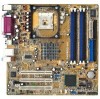
audio CODEC is onboard to provide 6-channel audio playback for 5.1 surround sound and over 90dB dynamic range. A digital audio connector is onboard to accommodate an optional S/PDIF (Sony/Philips Digital Interface) Out module. 1.4 Motherboard CPU socket 3. North Bridge controller 4. DDR DIMM sockets - Asus P4P800-MX | Motherboard DIY Troubleshooting Guide - Page 15
1 23 4 5 6 7 8 15 14 13 16 26 12 17 25 24 11 10 18 23 22 9 19 20 21 ASUS P4P800-MX motherboard 1-5 - Asus P4P800-MX | Motherboard DIY Troubleshooting Guide - Page 16
power supply. 2 CPU socket. A 478-pin surface mount, Zero Insertion Force (ZIF) socket for the Intel® Pentium® 4 Processor, with 800/533/400 MHz system bus that allows 6.4GB/s, 4.3GB/s, and 3.2GB/s data transfer rates, respectively. 3 North bridge controller. The Intel® 865GV Memory Controller Hub - Asus P4P800-MX | Motherboard DIY Troubleshooting Guide - Page 17
Serial port. This 9-pin COM1 port is for pointing devices or other serial devices. 26 PS/2 keyboard port. This purple connector is for a PS/2 keyboard. ASUS P4P800-MX motherboard 1-7 - Asus P4P800-MX | Motherboard DIY Troubleshooting Guide - Page 18
FLOPPY1 1.5 Motherboard layout PS/2KBMS T: Mouse B: Keyboard COM1 KBPWR1 24.5cm (9.6in) Socket 478 CHA_FAN1 CPU_FAN Super I/O ATX Power Connector DDR DIMM_B1 (64 bit,184-pin module) DDR DIMM_B2 (64 bit,184-pin module) P4P800-MX DDR DIMM_A1 (64 bit,184-pin module) DDR DIMM_A2 (64 bit,184- - Asus P4P800-MX | Motherboard DIY Troubleshooting Guide - Page 19
before you install motherboard components or change any motherboard settings. 1. Unplug the power cord from the wall socket before touching any component any motherboard component. P4P800-MX ® P4P800-MX Onboard LED SB_PWR1 ON Standby Power OFF Powered Off ASUS P4P800-MX motherboard 1-9 - Asus P4P800-MX | Motherboard DIY Troubleshooting Guide - Page 20
cm). Make sure to unplug the power cord before installing or removing the motherboard. Failure to do so may cause you physical injury and damage motherboard components. 1.7.1 Placement direction When installing the motherboard, make sure that you place it into the chassis in the correct orientation - Asus P4P800-MX | Motherboard DIY Troubleshooting Guide - Page 21
CPU. 2. Power up the system and enter BIOS Setup (see Chapter 2). Under the Advanced Menu, make sure that the item Hyper-Threading Technology is set to Enabled. The item appears only if you installed a CPU that supports HyperThreading Techonology. 3. Reboot the computer. ASUS P4P800-MX motherboard - Asus P4P800-MX | Motherboard DIY Troubleshooting Guide - Page 22
CPU is in place, push down the socket lever to secure the CPU. The lever clicks on the side tab to indicate that it is locked. 6. Install a CPU heatsink and fan following the instructions that came with the heatsink package. 7. Connect the CPU fan cable to the CPU_FAN1 connector on the motherboard - Asus P4P800-MX | Motherboard DIY Troubleshooting Guide - Page 23
Side Bus). Refer to Table 2. 5. DIMMs installed into any three sockets will function in single-channel mode. 6. When all four sockets are populated with 1GB DIMMs (total 4GB), the system may detect only 3+GB (a little less than 4GB) due to ICH5 resource allocation. ASUS P4P800-MX motherboard 1-13 - Asus P4P800-MX | Motherboard DIY Troubleshooting Guide - Page 24
, or • install identical DIMMs in DIMM_A1 and DIMM_B1 (blue sockets) and identical DIMMs in DIMM_A2 and DIMM_B2 (black sockets) Table 2 Memory frequency/CPU FSB synchronization This motherboard supports different memory frequencies depending on the CPU FSB (Front Side Bus) and the type of DDR DIMM - Asus P4P800-MX | Motherboard DIY Troubleshooting Guide - Page 25
retaining clips outward. 2. Align a DIMM on the socket such that the notch on the DIMM matches the break on the socket. 3. Firmly insert the DIMM into the socket until the retaining clips snap back in place and the DIMM is properly Unlocked Retaining Clip seated. ASUS P4P800-MX motherboard 1-15 - Asus P4P800-MX | Motherboard DIY Troubleshooting Guide - Page 26
for ISA or PCI devices. 1.10.2 IRQ assignments for this motherboard PCI slot 1 PCI slot 2 PCI slot 3 Onboard LAN A B C D E F GH shared shared shared shared When using PCI cards on shared slots, ensure that the drivers support "Share IRQ" or that the cards do not need IRQ assignments - Asus P4P800-MX | Motherboard DIY Troubleshooting Guide - Page 27
1.10.3 PCI slots There are three 32-bit PCI slots on this motherboard. The slots support PCI cards such as a LAN card, SCSI card, USB card, and other cards that comply with PCI specifications. ASUS P4P800-MX motherboard 1-17 - Asus P4P800-MX | Motherboard DIY Troubleshooting Guide - Page 28
(RTC) RAM in CMOS. You can clear the CMOS memory of date, time, and system setup parameters by erasing the BIOS setup to re-enter data. Except when clearing the RTC RAM, never remove the cap on CLRTC1 jumper default position. Removing the cap will cause system boot failure! P4P800-MX ® P4P800-MX - Asus P4P800-MX | Motherboard DIY Troubleshooting Guide - Page 29
to +5VSB to wake up from S3 and S4 sleep modes (no power to CPU, DRAM in slow refresh, power supply in reduced power mode). The USBPWR12 and corresponding setting in the BIOS. KBPWR1 12 23 +5V (Default) +5VSB P4P800-MX ® P4P800-MX Keyboard Power Setting ASUS P4P800-MX motherboard 1-19 - Asus P4P800-MX | Motherboard DIY Troubleshooting Guide - Page 30
-1 pin FLOPPY1) This connector supports the provided floppy drive ribbon cable. After connecting one end to the motherboard, connect the other end to the floppy drive. (Pin 5 is removed to prevent incorrect insertion when using ribbon cables with pin 5 plug). FLOPPY1 P4P800-MX NOTE: Orient the red - Asus P4P800-MX | Motherboard DIY Troubleshooting Guide - Page 31
Refer to the hard disk documentation for the jumper settings. BIOS supports specific device bootup. If you have more than two UltraATA100/66/33 (e.g. MS-DOS, Windows® 98/Me/NT4.0®). Refer to the Parallel ATA and Serial ATA device configurations on the next page. ASUS P4P800-MX motherboard 1-21 - Asus P4P800-MX | Motherboard DIY Troubleshooting Guide - Page 32
GND RSATA_RXP1 RSATA_RXN1 GND P4P800-MX SATA Connectors Parallel ATA and Serial ATA device configurations Following are the Parallel ATA and Serial ATA device configurations supported by Intel ICH5 specifications. Native operating systems (OS) are Windows® 2000/XP. ICH5 supports a maximum of six - Asus P4P800-MX | Motherboard DIY Troubleshooting Guide - Page 33
IDE Configuration" for details on the related BIOS items. BIOS item Windows 2000/XP Onboard IDE Operate Mode Enhanced Mode Enhanced Mode Support On S-ATA IDE Port Settings - Windows 98/Me/NT4.0 A B C Compatible Mode - Compatible Mode - Compatible Mode - Primary P-ATA+S-ATA Sec. P-ATA - Asus P4P800-MX | Motherboard DIY Troubleshooting Guide - Page 34
connectors (4-pin CD1, AUX1) These connectors allow you to receive stereo audio input from sound sources such as a CD-ROM, TV tuner, or MPEG card. CD1(Black) AUX1(White) ® P4P800-MX Internal Audio Connectors 6. Front panel audio connector (10-1 pin FP_AUDIO1) This is an interface for the Intel front - Asus P4P800-MX | Motherboard DIY Troubleshooting Guide - Page 35
or a game pad for playing games, and MIDI devices for playing or editing audio files. P4P800-MX +5V J1B2 J1CY GND GND J1CX J1B1 +5V ® P4P800-MX Game Connector GAME1 The USB 2.0/GAME module is purchased separately. ASUS P4P800-MX motherboard MIDI_IN J2B2 J2CY MIDI_OUT J2CX J2B1 +5V 1-25 - Asus P4P800-MX | Motherboard DIY Troubleshooting Guide - Page 36
allows digital instead of analog sound output. Connect one end of the audio cable to the S/PDIF Out connector on the motherboard, and the other end to the S/PDIF module. SPDIF1 ® P4P800-MX Digital Audio Connector The S/PDIF module is purchased separately. P4P800-MX +5V SPDIFOUT GND 1-26 Chapter - Asus P4P800-MX | Motherboard DIY Troubleshooting Guide - Page 37
driver before you can use the USB 2.0 capability. P4P800-MX USB+8V USB_P8USB_P8+ GND NC GND USB_P5+ USB_P5USB+5V USB+7V USB_P7USB_P7+ GND ® USB56 P4P800-MX USB 2.0 Connectors 1 USB78 1 NC GND USB_P6+ USB_P6USB+6V The USB 2.0/GAME module is purchased separately. ASUS P4P800-MX motherboard - Asus P4P800-MX | Motherboard DIY Troubleshooting Guide - Page 38
Ground Ground Speaker P4P800-MX IDE_LED+ IDE_LED- ON and SOFT OFF, depending on the BIOS or OS settings. Pressing the power switch SMI) This 2-pin connector allows you to manually place the system into a suspend mode, specific connector colors as described. 1-28 Chapter 1: Product introduction - Asus P4P800-MX | Motherboard DIY Troubleshooting Guide - Page 39
Chapter 2 This chapter tells how to change system settings through the BIOS Setup menus. Detailed descriptions of the BIOS parameters are also provided. BIOS information - Asus P4P800-MX | Motherboard DIY Troubleshooting Guide - Page 40
succeeding screen instructions to complete the process. 2. Copy the original (or the latest) motherboard BIOS to the bootable floppy disk. 2.1.2 Using AFUDOS to update the BIOS Update the BIOS using the AFUDOS.EXE utility in DOS environment. 1. Visit the ASUS website to download the latest BIOS file - Asus P4P800-MX | Motherboard DIY Troubleshooting Guide - Page 41
pressing during the Power-On Self Tests (POST). To update the BIOS using ASUS EZ Flash: 1. Visit the ASUS website to download the latest BIOS file for your motherboard and rename it to P4P8MXAS.ROM. Save the BIOS file to a floppy disk. 2. Reboot the system. ASUS P4P800-MX motherboard 2-3 - Asus P4P800-MX | Motherboard DIY Troubleshooting Guide - Page 42
support CD, or from a floppy disk that contains the BIOS file, in case the current BIOS on the motherboard fails or gets corrupted. 1. Prepare the support CD that came with the motherboard or a floppy disk that contains the motherboard BIOS (P4P8MXAS.ROM) before proceeding with the BIOS update - Asus P4P800-MX | Motherboard DIY Troubleshooting Guide - Page 43
found! Checking for CD-ROM... CD-ROM found. Reading file "p4p8mxas.rom". Completed. Start flashing... DO NOT shutdown or reset the system while updating the BIOS! Doing so may cause system boot failure! 4. When the BIOS update process is complete, reboot the system. ASUS P4P800-MX motherboard 2-5 - Asus P4P800-MX | Motherboard DIY Troubleshooting Guide - Page 44
Setup program This motherboard supports a programmable firmware hub (FWH) that you can update using the provided utility described in section "2.1 Managing and updating your BIOS." Use the BIOS Setup program when you are installing a motherboard, reconfiguring your system, or prompted to "Run Setup - Asus P4P800-MX | Motherboard DIY Troubleshooting Guide - Page 45
Secondary IDE Slave Third IDE Driver Fourth IDE Master IDE Configuration System Information [11:10:19] [Thu 03/27/2003] [1.44M, 3.5 in] [Disabled] [English] :[ST320413A] :[ASUS CD-S340] :[Not Detected] :[ Some of the navigation keys differ from one screen to another. ASUS P4P800-MX motherboard 2-7 - Asus P4P800-MX | Motherboard DIY Troubleshooting Guide - Page 46
specific Driver Fourth IDE Master IDE Configuration System Information [11:10:19] [Thu 03/27/2003] [1.44M, 3.5 in] [Disabled] [English] :[ST320413A] :[ASUS CD window." 2.2.7 Pop-up window Select a menu item then press Enter to display a pop-up window -up window Scroll bar 2.2.9 General help At - Asus P4P800-MX | Motherboard DIY Troubleshooting Guide - Page 47
Driver Fourth IDE Master IDE Configuration System Information [11:10:19] [Thu 03/27/2003] [1.44M, 3.5 in] [Disabled] [English] :[ST320413A] :[ASUS CD in.] 2.3.4 Language [English] This field allows you to choose the BIOS language version from the available options. ASUS P4P800-MX motherboard 2-9 - Asus P4P800-MX | Motherboard DIY Troubleshooting Guide - Page 48
, PIO Mode, Async DMA, Ultra DMA, and SMART monitoring) are autodetected by BIOS and are not user-configurable. These items show N/A if no IDE device is to the device occurs multiple sectors at a time if the device supports multisector transfer feature. When set to Disabled, the data transfer from - Asus P4P800-MX | Motherboard DIY Troubleshooting Guide - Page 49
Onboard IDE Operate Mode Enhanced Mode Support On IDE Detect Time Out (Sec such as Windows® 2000/XP. Configuration options: [Compatible Mode] compatibility. In this setting, you may use legacy OS on the Parallel ATA ports only if you did not install any Serial ATA device. ASUS P4P800-MX motherboard - Asus P4P800-MX | Motherboard DIY Troubleshooting Guide - Page 50
Information This menu gives you an overview of the general system specifications. The items in this menu are auto-detected by BIOS. AMI BIOS This item displays the auto-detected BIOS information. Processor This item displays the auto-detected CPU specification. 2-12 Chapter 2: BIOS information - Asus P4P800-MX | Motherboard DIY Troubleshooting Guide - Page 51
item displays the auto-detected system memory. 2.4 Advanced menu The Advanced menu items allow you to change the settings for the CPU and other system devices. Take caution when changing the settings of the values. If no USB device is detected, the item shows None. ASUS P4P800-MX motherboard 2-13 - Asus P4P800-MX | Motherboard DIY Troubleshooting Guide - Page 52
USB Ports] [4 USB Ports] [6 USB Ports] [8 USB Ports] Legacy USB Support [Auto] Allows you to enable or disable support for legacy USB devices. Setting to Auto allows the system to detect the presence of Device items appear only when there are installed USB devices. 2-14 Chapter 2: BIOS information - Asus P4P800-MX | Motherboard DIY Troubleshooting Guide - Page 53
as FDD (for example, ZIP drive). 2.4.2 CPU Configuration The items in this menu show the CPU-related information auto-detected by BIOS. Hyper-Threading Technology [Enabled] This item appears only if you installed an Intel Pentium 4 CPU that supports this feature. ASUS P4P800-MX motherboard 2-15 - Asus P4P800-MX | Motherboard DIY Troubleshooting Guide - Page 54
CPU External Frequency (MHz) DDR Reference Voltage DRAM Frequency Configure DRAM Timing by SPD [Auto] [Auto] [Auto] [Enabled] Graphic Adapter Priority Onboard Video Memory multiplied by the bus multiple equals the CPU speed. Configuration options: [Auto] [133 disabled, you can manually set the DRAM - Asus P4P800-MX | Motherboard DIY Troubleshooting Guide - Page 55
memory for AGP graphic data. Configuration options: [4MB] [8MB] [16MB] [32MB] [64MB] [128MB] [256MB] Spread Spectrum [Enabled] Enabled this item to conduce reduction of EMI. Configuration options: [Disabled] [Enabled] MPS Revision [1.1] Configuration options: [1.1] [1.4] ASUS P4P800-MX motherboard - Asus P4P800-MX | Motherboard DIY Troubleshooting Guide - Page 56
[Auto] [Auto] allows the BIOS to detect whether you are using any audio device. If an audio device is detected, the onboard audio controller is enabled; if no audio device is detected, the controller is disabled. Configuration options: [Disabled] [Auto] OnBoard LAN [Enabled] Allows you to enable - Asus P4P800-MX | Motherboard DIY Troubleshooting Guide - Page 57
for either PCI/PnP or legacy ISA devices, and setting the memory size block for legacy ISA devices. Take caution when changing Exit ESC Exit Plug and Play O/S [No] When set to [No], BIOS configures all the devices in the system. When set to [Yes] and if [224] [248] ASUS P4P800-MX motherboard 2-19 - Asus P4P800-MX | Motherboard DIY Troubleshooting Guide - Page 58
BIOS to use PCI bus mastering when reading/writing to IDE devices. Configuration options: [Disabled] [Enabled] IRQ xx [Available] When set to [Available], the specific options: [Available] [Reserved] Reserved Memory Size [Disabled] Sets the size of memory block reserved for legacy ISA devices. - Asus P4P800-MX | Motherboard DIY Troubleshooting Guide - Page 59
2.0 specifications. Configuration options: [No] [Yes] 2.5.4 ACPI APIC Support [Enabled] Allows you to enable or disable the ACPI support in the ASIC. When set to Enabled, the ACPI APIC table pointer is included in the RSDT pointer list. Configuration options: [Disabled] [Enabled] ASUS P4P800-MX - Asus P4P800-MX | Motherboard DIY Troubleshooting Guide - Page 60
Power Management (APM) feature. Configuration options: [Disbaled] [Enabled] Video Power Down Mode [Disabled] Allows you to select the video power down mode. Configuration options: [Disabled] [Standby] [Suspend options: [Power Off] [Power On] [Last State] 2-22 Chapter 2: BIOS information - Asus P4P800-MX | Motherboard DIY Troubleshooting Guide - Page 61
this parameter allows you to turn on the system through a PCI LAN or modem card. This feature requires an ATX power supply that CPU Temperature [xxxC/xxxF] The onboard hardware monitor automatically detects and displays the motherboard, CPU, and power supply temperatures. ASUS P4P800-MX motherboard - Asus P4P800-MX | Motherboard DIY Troubleshooting Guide - Page 62
monitor automatically detects and displays the CPU, chassis, and power fan speeds in rotations per minute (RPM). If any of the fans is not connected to the motherboard, the specific field shows N/A. VCORE Voltage, +3. "Press F1 to continue or DEL to enter SETUP". 2-24 Chapter 2: BIOS information - Asus P4P800-MX | Motherboard DIY Troubleshooting Guide - Page 63
number of device items that appear on the screen depends on the the number of devices installed in the system. Configuration options: [xxxxx Drive] [Disabled] ASUS P4P800-MX motherboard 2-25 - Asus P4P800-MX | Motherboard DIY Troubleshooting Guide - Page 64
mode for option ROM. Configuration options: [Force BIOS] [Keep Current] Bootup Num-Lock [On] Allows you to select the power-on state for the NumLock. Configuration options: [Off] [On] PS/2 Mouse Support [Auto] Allows you to enable or disable support fr PS/2 mouse. Configuration options: [Disabled - Asus P4P800-MX | Motherboard DIY Troubleshooting Guide - Page 65
Boot to OS/2 [No] Allows you to specify the OS/2 compatibility mode. Configuration options: [No] [Yes] Wait for 'F1' If Error [Enabled] When set to Enabled composed of letters and/ or numbers, then press Enter. Your password should have at least six characters. ASUS P4P800-MX motherboard 2-27 - Asus P4P800-MX | Motherboard DIY Troubleshooting Guide - Page 66
password box that appears, type a password composed of letters and/ or numbers, then press Enter. Your password should have at least six characters. 2-28 Chapter 2: BIOS information - Asus P4P800-MX | Motherboard DIY Troubleshooting Guide - Page 67
allow you to load the optimal or failsafe default values for the BIOS items, and save or discard your changes to the BIOS items. Pressing does not immediately exit this menu. Select option, a confirmation window appears. Select [Yes] to save changes and exit. ASUS P4P800-MX motherboard 2-29 - Asus P4P800-MX | Motherboard DIY Troubleshooting Guide - Page 68
to fields other than system date, system time, and password, the BIOS asks for a confirmation before exiting. Discard Changes This option allows menus. When you select this option or if you press , a confirmation window appears. Select [Yes] to load default values. Select Exit Saving Changes or - Asus P4P800-MX | Motherboard DIY Troubleshooting Guide - Page 69
Chapter 3 This chapter describes the contents of the support CD that comes with the motherboard package. Software support - Asus P4P800-MX | Motherboard DIY Troubleshooting Guide - Page 70
utility drivers that enhance the motherboard features. The contents of the support CD are subject to change at any time without notice. Visit the ASUS website for updates. 3.2.1 Running the support CD To begin using the support CD, simply insert the CD into your CD-ROM drive. The CD automatically - Asus P4P800-MX | Motherboard DIY Troubleshooting Guide - Page 71
2.0 Driver This item installs the USB 2.0 driver. REALTEK 10/100 LAN Driver This item installs the Realtek LAN driver to support 10/100 Mbps networking. 3.2.3 Utilities menu The Utilities menu shows the applications and other software that the motherboard supports. ASUS P4P800-MX motherboard 3-3 - Asus P4P800-MX | Motherboard DIY Troubleshooting Guide - Page 72
speed, CPU temperature, and system voltages, and alerts you on any detected problems. This utility helps you keep your computer at a healthy operating condition. ASUS Update This program allows you to download the latest version of the BIOS from the ASUS website. Before using the ASUS Update, make
-
 1
1 -
 2
2 -
 3
3 -
 4
4 -
 5
5 -
 6
6 -
 7
7 -
8
-
9
-
10
-
11
-
12
-
13
-
14
-
15
-
16
-
17
-
18
-
19
-
20
-
21
-
22
-
23
-
24
-
25
-
26
-
27
-
28
-
29
-
30
-
31
-
32
-
33
-
34
-
35
-
36
-
37
-
38
-
39
-
40
-
41
-
42
-
43
-
44
-
45
-
46
-
47
-
48
-
49
-
50
-
51
-
52
-
53
-
54
-
55
-
56
-
57
-
58
-
59
-
60
-
61
-
62
-
63
-
64
-
65
-
66
-
67
-
68
-
69
-
70
-
71
-
72
 |
 |

Motherboard
P4P800-MX
User Guide