Asus P4P800-X P4P800-X user's manual English version E1718
Asus P4P800-X Manual
 |
View all Asus P4P800-X manuals
Add to My Manuals
Save this manual to your list of manuals |
Asus P4P800-X manual content summary:
- Asus P4P800-X | P4P800-X user's manual English version E1718 - Page 1
Motherboard P4P800-X User Guide - Asus P4P800-X | P4P800-X user's manual English version E1718 - Page 2
express written permission of ASUSTeK COMPUTER INC. ("ASUS"). Product warranty or service will not be extended if: (1) the ASUS HAS BEEN ADVISED OF THE POSSIBILITY OF SUCH DAMAGES ARISING FROM ANY DEFECT OR ERROR IN THIS MANUAL OR PRODUCT. SPECIFICATIONS AND INFORMATION CONTAINED IN THIS MANUAL - Asus P4P800-X | P4P800-X user's manual English version E1718 - Page 3
guide viii Conventions used in this guide viii Where to find more information viii P4P800-X specification summary ix Chapter 1: Product introduction 1.1 Welcome 1-2 1.2 Package contents 1-2 1.3 Special features 1-2 1.4 Before you proceed 1-4 1.5 Motherboard overview 1-5 1.5.1 Motherboard - Asus P4P800-X | P4P800-X user's manual English version E1718 - Page 4
2-2 Using AFUDOS to copy the current BIOS 2-3 Using AFUDOS to update the BIOS 2-3 Using ASUS EZ Flash to update the BIOS 2-5 Recovering the BIOS with CrashFree BIOS 2 ....... 2-6 2.2 BIOS Setup program 2-8 2.2.1 2.2.2 2.2.3 2.2.4 2.2.5 2.2.6 2.2.7 2.2.8 2.2.9 BIOS menu screen 2-9 Menu bar - Asus P4P800-X | P4P800-X user's manual English version E1718 - Page 5
2-28 2.6.2 Boot Settings Configuration 2-28 2.6.3 Security 2-30 2.7 Exit menu 2-32 Chapter 3: Software support 3.1 Install an operating system 3-2 3.2 Support CD information 3-2 3.2.1 Running the support CD 3-2 3.2.2 Drivers menu 3-3 3.2.3 Utilities menu 3-3 3.2.4 ASUS Contact Information - Asus P4P800-X | P4P800-X user's manual English version E1718 - Page 6
energy and, if not installed and used in accordance with manufacturer's instructions, may cause harmful interference to radio communications. However, there is Class B limits for radio noise emissions from digital apparatus set out in the Radio Interference Regulations of the Canadian Department of - Asus P4P800-X | P4P800-X user's manual English version E1718 - Page 7
sure that your power supply is set to the correct voltage in your service technician or your retailer. Operation safety • Before installing the motherboard and adding devices on it, carefully read all the manuals , and staples away from connectors, slots, sockets and circuitry. • Avoid dust, humidity, - Asus P4P800-X | P4P800-X user's manual English version E1718 - Page 8
this guide To make sure that you perform certain tasks properly, take note of the following symbols used throughout this manual. WARNING updates. 1. ASUS Websites The ASUS websites worldwide provide updated information on ASUS hardware and software products. The ASUS websites are listed in the ASUS - Asus P4P800-X | P4P800-X user's manual English version E1718 - Page 9
P4P800-X specification summary CPU Chipset Front Side Bus (FSB) Memory Expansion slots Storage Audio LAN Special features AI Overclocking Rear panel I/O Socket 478 for Intel® Pentium® 4 / Celeron® processors Supports Intel® Hyper-Threading technology Intel® 865PE Intel® ICH5 800/533/400 MHz Dual- - Asus P4P800-X | P4P800-X user's manual English version E1718 - Page 10
P4P800-X specification summary Internal I/O BIOS features Industry standard Manageability Power Requirement Form Factor Support CD contents 2 x USB 2.0 connector for 4 additional USB ports CPU/Chassis fan connectors 20-pin/4-pin ATX 12V power connectors CD/AUX connectors Game/MIDI port connector - Asus P4P800-X | P4P800-X user's manual English version E1718 - Page 11
Chapter 1 This chapter describes the features of the P4P800-X motherboard. It includes brief descriptions of the motherboard components, and illustrations of the layout, jumper settings, and connectors. Product introduction - Asus P4P800-X | P4P800-X user's manual English version E1718 - Page 12
the list below. 1.2 Package contents Check your P4P800-X package for the following items. ASUS P4P800-X motherboard ASUS motherboard support CD 2 x Serial ATA cable 1 x UltraDMA 100/66 cable 1 x Floppy disk cable I/O shield Bag of extra jumper caps User Guide If any of the above items is damaged or - Asus P4P800-X | P4P800-X user's manual English version E1718 - Page 13
to set the BIOS items for overclocking. CrashFree BIOS 2 This feature allows you to restore the original BIOS data from a floppy disk or support CD in case when the BIOS codes and data are corrupted. This protection eliminates the need to buy a replacement ROM chip. ASUS P4P800-X motherboard 1-3 - Asus P4P800-X | P4P800-X user's manual English version E1718 - Page 14
before you install motherboard components or change any motherboard settings. 1. Unplug the power cord from the wall socket before touching any component plugging in any motherboard component. The illustration below shows the location of the onboard LED. P4P800-X ® P4P800-X Onboard LED SB_PWR - Asus P4P800-X | P4P800-X user's manual English version E1718 - Page 15
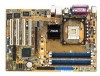
I/O 3Mb FWH Intel 865PE MCH SEC_IDE Accelerated Graphics Port (AGP) CLRTC CHASSIS PCI1 PCI2 P4P800-X PCI3 ® PCI4 COM2 GAME Intel ICH5 FLOPPY CR2032 3V Lithium Cell CMOS Power SATA2 SATA1 SB_PWR CHA_FAN USBPW56 USBPW78 USB56 USB78 PANEL 30.5cm (12.0in) ASUS P4P800-X motherboard 1-5 - Asus P4P800-X | P4P800-X user's manual English version E1718 - Page 16
in the image below. 1.5.3 Screw holes Place seven (7) screws into the holes indicated by circles to secure the motherboard to the chassis. Do not overtighten the screws! Doing so may damage the motherboard. Place this side towards the rear of the chassis 1-6 Chapter 1: Product introduction - Asus P4P800-X | P4P800-X user's manual English version E1718 - Page 17
1 that should match a specific corner of the CPU socket. P4P800-X ® P4P800-X CPU Socket 478 Gold Arrow Incorrect installation of the CPU into the socket may bend the pins and severely damage the CPU! Notes on Intel® Hyper-Threading Technology • This motherboard supports Intel® Pentium® 4 CPUs - Asus P4P800-X | P4P800-X user's manual English version E1718 - Page 18
Follow these steps to install a CPU. 1. Locate the 478-pin ZIF socket on the motherboard. 2. Unlock the socket by pressing the lever sideways, then lift it up to a 90°- 100° angle. Socket Lever Make sure that the socket lever is lifted up to 90°-100° angle, otherwise the CPU does not fit in - Asus P4P800-X | P4P800-X user's manual English version E1718 - Page 19
3+ GB (a little less than 4 GB) due to the SouthBridge resource allocation. • Three DDR DIMMs installed into any three memory sockets will function in single channel mode. • Make sure that the memory frequency matches the CPU FSB. Refer to Table 2 for configurations. ASUS P4P800-X motherboard 1-9 - Asus P4P800-X | P4P800-X user's manual English version E1718 - Page 20
) and another same size pair in DIMM_A2 and DIMM_B2 (black sockets) Table 2 Memory frequency/CPU FSB synchronization This motherboard supports different memory frequencies depending on the CPU FSB (Front Side Bus) and the type of DDR DIMM. CPU FSB 800 MHz 533 MHz 400 MHz DDR DIMM Type PC3200 - Asus P4P800-X | P4P800-X user's manual English version E1718 - Page 21
as one pair of Dual-channel memory configuration. C - support for 4 modules inserted into all the slots as two pairs of Dual-channel memory configuration. Obtain DDR DIMMs only from ASUS qualified vendors. Visit the ASUS website (www.asus.com) for the latest QVL. ASUS P4P800-X motherboard 1-11 - Asus P4P800-X | P4P800-X user's manual English version E1718 - Page 22
a DIMM Follow these steps to install a DIMM. 1. Unlock a DIMM socket by pressing the retaining clips outward. 2. Align a DIMM on the socket such that the notch on the DIMM matches the break on the socket. 3. Firmly insert the DIMM into the socket until the retaining clips snap back in place and the - Asus P4P800-X | P4P800-X user's manual English version E1718 - Page 23
- - - shared - - - - -- When using PCI cards on shared slots, ensure that the drivers support "Share IRQ" or that the cards do not need IRQ assignments. Otherwise, conflicts will arise between the two PCI groups, making the system unstable and the card inoperable. ASUS P4P800-X motherboard 1-13 - Asus P4P800-X | P4P800-X user's manual English version E1718 - Page 24
one with +1.5V specification. Note the notches on the card golden fingers to ensure that they fit the AGP slot on the motherboard. This motherboard does not support 3.3V AGP cards. Install only +1.5V or 0.8V AGP cards on this motherboard. P4P800-X ® Keyed for 1.5v P4P800-X Accelerated Graphics - Asus P4P800-X | P4P800-X user's manual English version E1718 - Page 25
CMOS You do not need to clear the RTC when the system hangs due to overclocking. For system failure due to overclocking, use the C.P.R. (CPU Parameter Recall) feature. Shut down and reboot the system so BIOS can automatically reset parameter settings to default values. ASUS P4P800-X motherboard - Asus P4P800-X | P4P800-X user's manual English version E1718 - Page 26
(CPU stopped, DRAM refreshed, system running in low power mode) using the connected USB devices. Set to +5VSB to wake up from S3 and S4 sleep modes (no power to CPU, or in sleep mode. P4P800-X ® USBPW12 USBPW34 2 1 +5V 3 2 +5VSB (Default) USBPW56 USBPW78 12 23 P4P800-X USB device wake up +5V - Asus P4P800-X | P4P800-X user's manual English version E1718 - Page 27
(USB) ports are available for connecting USB 2.0 devices. 9. Serial connector. This 9-pin COM1 port is for serial devices. 10. S/PDIF out jack. This jack connects to external audio output devices. 11. PS/2 keyboard port. This purple connector is for a PS/2 keyboard. ASUS P4P800-X motherboard 1-17 - Asus P4P800-X | P4P800-X user's manual English version E1718 - Page 28
supports the provided floppy drive ribbon cable. After connecting one end to the motherboard, P4P800-X Floppy disk drive connector 2. IDE connectors (40-1 pin PRI_IDE, SEC_IDE) This connector supports 1. Follow the hard disk drive documentation when setting the device in master or slave mode. 2. - Asus P4P800-X | P4P800-X user's manual English version E1718 - Page 29
will disable the ICH5 chipset support to one of the IDE channels (either primary or secondary channel). • Hot plug support for Serial ATA drive and connections are not available in this motherboard. • Install Windows® XP Service Pack 1 when using Serial ATA. ASUS P4P800-X motherboard 1-19 - Asus P4P800-X | P4P800-X user's manual English version E1718 - Page 30
configurations. See section "2.3.5 IDE Configuration" for details on the related BIOS items. BIOS item Windows 2000/XP Onboard IDE Operate Mode Enhanced Mode Enhanced Mode Support On S-ATA IDE Port Settings - Windows 98/Me/NT4.0 A B C Compatible Mode - Compatible Mode - Compatible Mode - Asus P4P800-X | P4P800-X user's manual English version E1718 - Page 31
receive stereo audio input from sound sources such as a CD-ROM, TV tuner, or MPEG card. CD (Black) P4P800-X ® AUX (White) P4P800-X Internal audio connectors Right Audio Channel Ground Ground Left Audio Channel Right Audio Channel Ground Ground Left Audio Channel ASUS P4P800-X motherboard 1-21 - Asus P4P800-X | P4P800-X user's manual English version E1718 - Page 32
+12V Rotation USB+5V USB_P8USB_P8+ GND NC USB+5V USB_P6USB_P6+ GND NC USB+5V USB_P7USB_P7+ GND P4P800-X R USB56 1 P4P800-X USB 2.0 connectors USB+5V USB_P5USB_P5+ GND USB78 1 • The USB 2.0 module is purchased separately. • Install the USB 2.0 driver before using the USB 2.0 feature. 1-22 - Asus P4P800-X | P4P800-X user's manual English version E1718 - Page 33
the front panel cable that allows convenient connection and control of audio devices. Be default, the pins labeled LINE OUT_R/BLINE_OUT_R and the cap from the pins. P4P800-X ® CHASSIS GND Chassis Signal (Default) +5VSB_MB P4P800-X Chassis intrusion connector ASUS P4P800-X motherboard 1-23 - Asus P4P800-X | P4P800-X user's manual English version E1718 - Page 34
) This connector is for the S/PDIF audio module to allow digital sound output. Connect one end of the S/PDIF audio cable to this connector and the other end to the S/PDIF module. P4P800-X R SPDIF_OUT GND SPDIFOUT +5V P4P800-X Digital audio connector The S/PDIF module is purchased separately - Asus P4P800-X | P4P800-X user's manual English version E1718 - Page 35
V PLED +5V Ground Ground Speaker PANEL HD_LED+ HD_LEDPWRBIN Ground Reset Ground P4P800-X R P4P800-X System panel connector IDELED Reset SW ATX Power Switch* * Requires an ATX power supply the case-mounted speaker and allows you to hear system beeps and warnings. ASUS P4P800-X motherboard 1-25 - Asus P4P800-X | P4P800-X user's manual English version E1718 - Page 36
to the case-mounted reset switch for rebooting the ON and SLEEP, or ON and SOFT OFF, depending on the BIOS or OS settings. Pressing the power switch while in the ON mode for more than color-coded for easy and foolproof connection. Take note of the specific connector colors as described. 1- - Asus P4P800-X | P4P800-X user's manual English version E1718 - Page 37
Chapter 2 This chapter tells how to change system settings through the BIOS Setup menus. Detailed descriptions of the BIOS parameters are also provided. BIOS information - Asus P4P800-X | P4P800-X user's manual English version E1718 - Page 38
Basic Input/Output System (BIOS) setup. 1. ASUS AFUDOS - Updates the BIOS using a bootable floppy disk in DOS mode. 2. ASUS EZ Flash - Updates the BIOS using a floppy disk during POST. 3. ASUS CrashFree BIOS 2 - Updates the BIOS using a bootable floppy disk or the motherboard support CD. Refer to - Asus P4P800-X | P4P800-X user's manual English version E1718 - Page 39
screen instructions. 2. Copy the original (or the latest) motherboard BIOS to the bootable floppy disk. 2.1.2 Using AFUDOS to update the BIOS To update the BIOS using the AFUDOS.EXE utility: 1. Visit the ASUS website (www.asus.com) to download the latest BIOS file for your motherboard. Save the BIOS - Asus P4P800-X | P4P800-X user's manual English version E1718 - Page 40
When the BIOS update process is complete, the utility returns to the DOS prompt. A:\>afudos /iP4P800X.ROM AMI Firmware Update Utility - Version 1.10 Copyright (C) 2002 American Megatrends, Inc. All rights reserved. Reading file ..... done Erasing flash .... done Writing flash .... 0x0008CC00 (9%) - Asus P4P800-X | P4P800-X user's manual English version E1718 - Page 41
. Make sure to rename the downloaded BIOS file as "P4P800X.ROM". 4. Insert the floppy disk that contains the BIOS file. If all the necessary files are found in the floppy disk, EZ Flash performs the BIOS update process and automatically reboots the system when done. ASUS P4P800-X motherboard 2-5 - Asus P4P800-X | P4P800-X user's manual English version E1718 - Page 42
from a floppy disk that contains the BIOS file, in case the current BIOS on the motherboard fails or gets corrupted. • Prepare the support CD that came with the motherboard or a floppy disk that contains the motherboard BIOS before proceeding with the BIOS update process. • If you have saved a copy - Asus P4P800-X | P4P800-X user's manual English version E1718 - Page 43
while updating the BIOS! Doing so may cause system boot failure! 2. When the BIOS update process is complete, reboot the system. The recovered BIOS may not be the latest BIOS version for this motherboard. Visit ASUS website (www.asus.com) to download the latest BIOS file. ASUS P4P800-X motherboard - Asus P4P800-X | P4P800-X user's manual English version E1718 - Page 44
feature or change the power management settings. This requires you to reconfigure your system using the BIOS Setup program so that the computer can recognize these changes and record them in the CMOS RAM of the firmware hub. The firmware hub on the motherboard stores the Setup utility. When you - Asus P4P800-X | P4P800-X user's manual English version E1718 - Page 45
2.2.1 BIOS menu screen Menu items Menu bar Configuration fields General help System Time System Date Legacy Diskette A [ . Use the navigation keys to select items in the menu and change the settings. Some of the navigation keys differ from one screen to another. ASUS P4P800-X motherboard 2-9 - Asus P4P800-X | P4P800-X user's manual English version E1718 - Page 46
ASUS window with the configuration options for that item. 2.2.8 Scroll bar A scroll bar appears on the right side of a menu screen when there are items that do not fit on the screen. Press Up/Down arrow keys or PageUp/PageDown keys to display the other items on the screen. Advanced Chipset settings - Asus P4P800-X | P4P800-X user's manual English version E1718 - Page 47
Refer to section "2.2.1 BIOS menu screen" for set the system date. 2.3.3 Legacy Diskette A [1.44M, 3.5 in.] Sets the type of floppy drive installed. Configuration options: [Disabled] [360K, 5.25 in.] [1.2M , 5.25 in.] [720K , 3.5 in.] [1.44M, 3.5 in.] [2.88M, 3.5 in.] ASUS P4P800-X motherboard - Asus P4P800-X | P4P800-X user's manual English version E1718 - Page 48
) are autodetected by BIOS and are not user-configurable. These items show N/A if no IDE device is installed in the system. Type [Auto] Selects the type of IDE drive. Setting to Auto allows automatic selection of the appropriate IDE device type. Select CDROM if you are specifically configuring a CD - Asus P4P800-X | P4P800-X user's manual English version E1718 - Page 49
system (OS) that you installed. Set to Enhanced Mode if you are using native OS, such as Windows 2000/XP. Set to Compatible Mode if you are using legacy OS including MS-DOS, Linux, Windows ME/98/NT4.0. Configuration options: [Compatible Mode] [Enhanced Mode] ASUS P4P800-X motherboard 2-13 - Asus P4P800-X | P4P800-X user's manual English version E1718 - Page 50
Enhanced Mode Support On [S-ATA] The default setting S-ATA allows you to use native OS (Windows 2000/XP) on Serial ATA and Parallel ATA ports. We recommend that you do not change the default setting for better OS compatibility. In this setting, you may use legacy OS (Windows ME/98/98SE/NT4.0) on the - Asus P4P800-X | P4P800-X user's manual English version E1718 - Page 51
of the preset overclocking options. Configuration options: [Manual] [Standard] [Overclock 5%] [Overclock 10%] [Overclock 20%] [Overclock 30%] Selecting a very high CPU frequency may cause the system to become unstable! If this happens, revert to the default setting. ASUS P4P800-X motherboard 2-15 - Asus P4P800-X | P4P800-X user's manual English version E1718 - Page 52
a specific CPU VCore voltage. The configurations depends on the type of CPU installed. Refer to the CPU documentation before setting the CPU VCore voltage. A very high Vcore voltage may severely damage the CPU! When you set the AI Overclocking Tuner item to [Manual], the related overclocking items - Asus P4P800-X | P4P800-X user's manual English version E1718 - Page 53
enable or disable the processor Hyper-Threading Technology. Configuration options: [Disabled] [Enabled] The item Hyper-Threading Technology appears only if you installed an Intel Pentium 4 CPU that supports this feature. See page1-7 for details. ASUS P4P800-X motherboard 2-17 - Asus P4P800-X | P4P800-X user's manual English version E1718 - Page 54
item is enabled, the DRAM timing parameters are set according to the DRAM SPD (Serial Presence Detect). When disabled, you can manually set the DRAM timing parameters through the DRAM sub-items /write command. Configuration options: [4 Clocks] [3 Clocks] [2 Clocks] 2-18 Chapter 2: BIOS information - Asus P4P800-X | P4P800-X user's manual English version E1718 - Page 55
Memory Acceleration Mode [Auto] This field when [Enabled] minimize latencies from CPU to memory to boost system performance. Configuration options: [Auto] [Enabled] [1.4] Sets the Multi-Processor Specification (MPS) version. Configuration options: [1.1] [1.4] ASUS P4P800-X motherboard 2-19 - Asus P4P800-X | P4P800-X user's manual English version E1718 - Page 56
[Auto] [Auto] allows the BIOS to detect whether you are using any audio device. If an audio device is detected, the onboard audio controller is enabled; if no audio device is detected, the controller is disabled. Configuration options: [Disabled] [Auto] OnBoard LAN [Enabled] Allows you to enable - Asus P4P800-X | P4P800-X user's manual English version E1718 - Page 57
and Play O/S [No] When set to [No], BIOS configures all the devices in the system. When set to [Yes] and if you installed a Plug & Play operating system, the operating system configures the Plug & Play devices not required for boot. Configuration options: [No] [Yes] ASUS P4P800-X Motherboard 2-21 - Asus P4P800-X | P4P800-X user's manual English version E1718 - Page 58
[Enabled] PCI IDE BusMaster [Enabled] Allows BIOS to use PCI bus mastering when reading/writing to IDE devices. Configuration options: [Disabled] [Enabled] IRQ xx [Available] When set to [Available], the specific IRQ is free for use of PCI/PnP devices. When set to [Reserved], the IRQ is reserved for - Asus P4P800-X | P4P800-X user's manual English version E1718 - Page 59
you to select the number of seconds POST waits for the USB mass storage device after the start unit command. The message "No USB mass storage device detected" appears if none is installed in the system. Configuration options: [10 Sec ] [20 Sec] [30 Sec] [40 Sec] ASUS P4P800-X Motherboard 2-23 - Asus P4P800-X | P4P800-X user's manual English version E1718 - Page 60
to invoke VGA BIOS POST on S3/STR resume. Configuration options: [No] [Yes] 2.5.3 ACPI 2.0 Support [No] Allows you to add more tables for ACPI 2.0 specifications. Configuration options: [No] [Yes] 2.5.4 ACPI APIC Support [Enabled] Enables or disables the ACPI support in the ASIC. When set to Enabled - Asus P4P800-X | P4P800-X user's manual English version E1718 - Page 61
[On/Off] Allows the system to go into On/Off mode or suspend mode when the power button is pressed. Configuration options: [On/Off] [Suspend] ASUS P4P800-X motherboard 2-25 - Asus P4P800-X | P4P800-X user's manual English version E1718 - Page 62
off causes an initialization string that turns the system power on. Power On By PCI Devices [Disabled] When set to [Enabled], this parameter allows you to turn on the system through a PCI LAN or modem card. This feature requires an ATX power supply that provides at least 2A on the +5VSB lead - Asus P4P800-X | P4P800-X user's manual English version E1718 - Page 63
monitor automatically detects and displays the CPU, chassis, and power fan speeds in rotations per minute (RPM). If any of the fans is not connected to the motherboard, the specific field shows N/A. VCORE Voltage, +3. to "Press F1 to continue or DEL to enter SETUP". ASUS P4P800-X motherboard 2-27 - Asus P4P800-X | P4P800-X user's manual English version E1718 - Page 64
Configuration Boot Settings Configuration Quick Boot Full Screen Logo AddOn ROM Display Mode Bootup Num-Lock PS/2 Mouse Support Typematic Rate Boot to OS/2 Wait for 'F1' If Error Hit 'DEL' Message Display Interrupt 19 Capture [Enabled] [Enabled] [Force BIOS] [On] [Auto] [Fast] [No] [Enabled - Asus P4P800-X | P4P800-X user's manual English version E1718 - Page 65
system displays the message "Press DEL to run Setup" during POST. Configuration options: [Disabled] [Enabled] Interrupt 19 Capture [Disabled] When set to [Enabled], this function allows the option ROMs to trap Interrupt 19. Configuration options: [Disabled] [Enabled] ASUS P4P800-X motherboard 2-29 - Asus P4P800-X | P4P800-X user's manual English version E1718 - Page 66
same steps as in setting a user password. To clear the supervisor password, select the Change Supervisor Password then press Enter. The message "Password Uninstalled" appears. If you forget your BIOS password, you can clear it by erasing the CMOS Real Time Clock (RTC) RAM. See section "1.9 Jumpers - Asus P4P800-X | P4P800-X user's manual English version E1718 - Page 67
user password. Password Check [Setup] When set to [Setup], BIOS checks for user password when accessing the Setup utility. When set to [Always], BIOS checks for user password both when accessing Setup and booting the system. Configuration options: [Setup] [Always] ASUS P4P800-X motherboard 2-31 - Asus P4P800-X | P4P800-X user's manual English version E1718 - Page 68
RAM. The CMOS RAM is sustained by an onboard backup battery and stays on even when the PC is turned off. When you select this option, a confirmation window to fields other than system date, system time, and password, the BIOS asks for a confirmation before exiting. Discard Changes Allows you to - Asus P4P800-X | P4P800-X user's manual English version E1718 - Page 69
Chapter 3 This chapter describes the contents of the support CD that comes with the motherboard package. Software support - Asus P4P800-X | P4P800-X user's manual English version E1718 - Page 70
3.1 Install an operating system ® This motherboard supports Windows® 98SE/ME/2000/XP/2003 Server operating system (OS). Always install the latest OS version and corresponding updates so you can maximize the features of your hardware. Because motherboard settings and hardware options vary, use the - Asus P4P800-X | P4P800-X user's manual English version E1718 - Page 71
audio feature. USB 2.0 Driver This item installs the USB 2.0 driver. REALTEK RTL8100C 10/100M LAN Driver This item installs the Realtek LAN driver to support 10/100 Mbps networking. 3.2.3 Utilities menu The Utilities menu shows the applications and other software that the motherboard supports. ASUS - Asus P4P800-X | P4P800-X user's manual English version E1718 - Page 72
allows you to download the latest version of the BIOS from the ASUS website. Before using the ASUS Update, make sure that you have an Internet connection so you can connect to the ASUS website. Installing ASUS Update also installs ASUS Mylogo™. To use the MyLogo™ feature, set the BIOS "Quick Boot
-
 1
1 -
 2
2 -
 3
3 -
 4
4 -
 5
5 -
 6
6 -
 7
7 -
8
-
9
-
10
-
11
-
12
-
13
-
14
-
15
-
16
-
17
-
18
-
19
-
20
-
21
-
22
-
23
-
24
-
25
-
26
-
27
-
28
-
29
-
30
-
31
-
32
-
33
-
34
-
35
-
36
-
37
-
38
-
39
-
40
-
41
-
42
-
43
-
44
-
45
-
46
-
47
-
48
-
49
-
50
-
51
-
52
-
53
-
54
-
55
-
56
-
57
-
58
-
59
-
60
-
61
-
62
-
63
-
64
-
65
-
66
-
67
-
68
-
69
-
70
-
71
-
72
 |
 |

Motherboard
P4P800-X
User Guide