Asus P4PE-X SE P4PE-X User Manual
Asus P4PE-X SE Manual
 |
View all Asus P4PE-X SE manuals
Add to My Manuals
Save this manual to your list of manuals |
Asus P4PE-X SE manual content summary:
- Asus P4PE-X SE | P4PE-X User Manual - Page 1
Motherboard P4PE-X User Guide - Asus P4PE-X SE | P4PE-X User Manual - Page 2
Product warranty or service will not be extended if: (1) the product is repaired, modified or altered, unless such repair, modification of alteration is authorized in writing by ASUS; or (2) the serial number of the product is defaced or missing. ASUS PROVIDES THIS MANUAL "AS IS" WITHOUT WARRANTY - Asus P4PE-X SE | P4PE-X User Manual - Page 3
assignments for this motherboard 1-14 1.11 Jumpers 1-15 1.12 Connectors 1-16 Chapter 2: BIOS information 2.1 Managing and updating your BIOS 2-2 2.1.1 Using ASUS EZ Flash to update the BIOS 2-2 2.1.2 Using AFLASH to update the BIOS 2-4 2.1.3 CrashFree BIOS feature 2-7 2.1.4 BIOS beep codes - Asus P4PE-X SE | P4PE-X User Manual - Page 4
Safeguards Contents 2.2 BIOS Setup program 2-8 2.2.1 BIOS menu bar 2-8 2.2.2 Legend bar 2-9 2.3 Main Menu 2-10 2.3.1 Primary support 3.1 Install an operating system 3-2 3.2 Support CD information 3-2 3.2.1 Running the support CD 3-2 3.2.2 Drivers menu 3-3 3.2.3 Utilities menu 3-4 3.2.4 ASUS - Asus P4PE-X SE | P4PE-X User Manual - Page 5
and used in accordance with manufacturer's instructions, may cause harmful interference to radio determined by turning the equipment off and on, the user is encouraged to try to correct the interference by one radio noise emissions from digital apparatus set out in the Radio Interference Regulations - Asus P4PE-X SE | P4PE-X User Manual - Page 6
sure that your power supply is set to the correct voltage in your service technician or your retailer. Operation safety • Before installing the motherboard and adding devices on it, carefully read all the manuals problems with the product, contact a qualified service technician or your retailer. vi - Asus P4PE-X SE | P4PE-X User Manual - Page 7
in this guide To make sure that you perform certain tasks properly, take note of the following symbols used throughout this manual. WARNING: ASUS Websites The ASUS websites worldwide provide updated information on ASUS hardware and software products. The ASUS websites are listed in the ASUS - Asus P4PE-X SE | P4PE-X User Manual - Page 8
150 Li-Te Road, Peitou, Taipei, Taiwan 112 General Tel: +886-2-2894-3447 General Fax: +886-2-2894-3449 General Email: [email protected] Technical Support MB/Others (Tel): +886-2-2890-7121 (English) Notebook (Tel): +886-2-2890-7122 (English) Desktop/Server (Tel): +886-2-2890-7123 (English - Asus P4PE-X SE | P4PE-X User Manual - Page 9
P4PE-X specifications summary CPU Chipset Front Side Bus (FSB) Memory Expansion slots IDE Audio (optional) LAN (optional) Special features Rear panel I/O Internal I/O Socket 478 for Intel® Pentium® 4 On-die 512KB/256KB L2 cache with full speed Intel® Hyper-Threading technology ready New power - Asus P4PE-X SE | P4PE-X User Manual - Page 10
Form Factor Support CD contents 2Mb Flash ROM, Award BIOS, TCAV, PnP, DMI2.0, SM BIOS2.3, CrashFree BIOS, ASUS EZ Flash PCI 2.2, USB 2.0 WfM 2.0. DMI 2.0, WOL/WOR by PME, chassis intrusion, SMBus ATX form factor: 12 in x 9.0 in (30.5 cm x 22.9 cm) Device drivers ASUS PC Probe ASUS LiveUpdate Trend - Asus P4PE-X SE | P4PE-X User Manual - Page 11
Chapter 1 This chapter describes the features of the P4PE-X motherboard. It includes brief descriptions of the motherboard components, and illustrations of the layout, jumper settings, and connectors. Product introduction - Asus P4PE-X SE | P4PE-X User Manual - Page 12
for the following items. ASUS P4PE-X motherboard ATX form factor: 12 in x 9 in (30.5 cm x 22.9 cm) ASUS P4PE-X series support CD 80-conductor ribbon cables for UltraDMA/66/100/133 IDE drives Ribbon cable for a 3.5-inch floppy drive I/O shield Bag of extra jumper caps User Guide If any of the above - Asus P4PE-X SE | P4PE-X User Manual - Page 13
the CPU default setting for each parameter. CrashFree BIOS This feature allows you to restore the original BIOS data from a floppy disk in cases when the BIOS codes and data are corrupted. This protection eliminates the need to buy a replacement ROM chip. ASUS P4PE-X motherboard user guide 1-3 - Asus P4PE-X SE | P4PE-X User Manual - Page 14
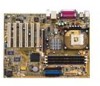
components Before you install the motherboard, learn about its major components and available features to facilitate the installation and future upgrades. Refer to the succeeding pages for the component descriptions. 1 23 4 5 6 7 16 15 8 14 13 17 26 25 1-4 12 11 10 9 18 19 20 - Asus P4PE-X SE | P4PE-X User Manual - Page 15
3 North bridge controller. The Intel® 845PE Memory Controller Hub (MCH) BIOS program. 10 Standby power LED. This LED lights up if there is a standby power on the motherboard support bus master PCI cards like SCSI or LAN cards with 133MB/s maximum throughput. ASUS P4PE-X motherboard user guide 1-5 - Asus P4PE-X SE | P4PE-X User Manual - Page 16
an AC'97 CODEC that allows 6-channel audio playback. The audio CODEC provides six DAC channels for 5.1 surround sound, S/PDIF output, AUX and Line In stereo inputs, integrated headphone amplifier, greater than 90dB dynamic range, and stereo Mic PREAMP support. 15 LAN controller. The BroadCom BCM4401 - Asus P4PE-X SE | P4PE-X User Manual - Page 17
PCI1 P4PE-X PCI2 PCI3 PCI4 PCI5 PCI6 01 23 45 Intel I/O Controller Hub (ICH4) ® CR2032 3V Lithium Cell CMOS Power CLRTC ASUS ASIC with Hardware Monitor SB_PWR1 CHASSIS1 4Mbit Firmware Hub Super I/O IDE_LED1 FP_AUDIO1 USB_56 GAME1 PANEL1 30.5cm (12.0in) ASUS P4PE-X motherboard user guide - Asus P4PE-X SE | P4PE-X User Manual - Page 18
Take note of the following precautions before you install motherboard components or change any motherboard settings. 1. Unplug the power cord from the wall removing or plugging in any motherboard component. ® P4PE-X P4PE-X Onboard LED SB_PWR1 ON Standby Power OFF Powered Off 1-8 Chapter - Asus P4PE-X SE | P4PE-X User Manual - Page 19
in the image below. 1.7.2 Screw holes Place seven (7) screws into the holes indicated by circles to secure the motherboard to the chassis. Do not overtighten the screws! Doing so may damage the motherboard. Place this side towards the rear of the chassis ASUS P4PE-X motherboard user guide 1-9 - Asus P4PE-X SE | P4PE-X User Manual - Page 20
www.intel.com/ info/hyperthreading. To use the Hyper-Threading Technology on this motherboard: 1. Install a Pentium 4 CPU that supports Hyper-Threading Technology. 2. Power up the system and enter BIOS Setup. Under the Boot Menu, make sure that the item Hyper-Threading Technology is set to Enabled - Asus P4PE-X SE | P4PE-X User Manual - Page 21
to secure the CPU. The lever clicks on the side tab to indicate that it is locked. 6. Install a CPU heatsink and fan following the instructions that came with the heatsink package. 7. Connect the CPU fan cable to the CPU_FAN1 connector on the motherboard. ASUS P4PE-X motherboard user guide 1-11 - Asus P4PE-X SE | P4PE-X User Manual - Page 22
a PC3200 (400MHz) DDR module, you need to install a CPU with 800MHz FSB. ® P4PE-X 80 Pins 104 Pins P4PE-X 184-Pin DDR DIMM Sockets 1.9.1 Memory configurations You may install any DDR DIMMs with 64MB, 16-bit DDR DIMMs are not supported on this motherboard. 1-12 Chapter 1: Product introduction - Asus P4PE-X SE | P4PE-X User Manual - Page 23
socket. 3. Firmly insert the DIMM into the socket until the retaining clips snap back in place and the DIMM is properly seated. Unlocked Retaining Clip ASUS P4PE-X motherboard user guide 1-13 - Asus P4PE-X SE | P4PE-X User Manual - Page 24
instructions that came with the chassis. NOTE: The AGP slot supports only 1.5V AGP cards. 2. Turn on the system and change the necessary BIOS settings, if any. See Chapter 2 for BIOS information. 3. Assign an IRQ to the card. Refer to the tables below. 4. Install the drivers motherboard Onboard LAN ( - Asus P4PE-X SE | P4PE-X User Manual - Page 25
erase the RTC RAM: 1. Turn OFF the computer and unplug the power cord. 2. Move the jumper cap from pins 1-2 (default) to pins 2-3. Keep the cap on pins 2-3 for about 5~10 reboot the system so BIOS can automatically reset parameter settings to default values. ASUS P4PE-X motherboard user guide 1-15 - Asus P4PE-X SE | P4PE-X User Manual - Page 26
section describes and illustrates the internal connectors on the motherboard. 1. Hard disk activity LED (2-pin IDE_LED1) This a jumper cap. If you wish to use the chassis intrusion detection feature, remove the jumper cap from the pins. CHASSIS1 +5VSB_MB Chassis Signal GND ® P4PE-X P4PE-X - Asus P4PE-X SE | P4PE-X User Manual - Page 27
slave device by setting its jumper accordingly. Refer to the hard disk documentation for the jumper settings. BIOS supports specific device bootup. P4PE-X NOTE: Orient the red markings on the floppy ribbon cable to PIN 1. PIN 1 P4PE-X Floppy Disk Drive Connector ASUS P4PE-X motherboard user guide - Asus P4PE-X SE | P4PE-X User Manual - Page 28
digital instead of analog sound output. Connect one end of the audio cable to the S/PDIF Out connector on the motherboard, and the other end to the S/PDIF module. The S/PDIF module is purchased separately. ® P4PE-X +5V SPDIFOUT GND SPDIF1 P4PE-X Digital Audio Connector 1-18 Chapter 1: Product - Asus P4PE-X SE | P4PE-X User Manual - Page 29
(4-pin CD1, AUX1) These connectors allow you to receive stereo audio input from sound sources such as a CD-ROM, TV tuner, or MPEG card. ® P4PE-X CD1(Black) AUX1 (White) Left Audio Channel Ground Ground Right Audio Channel P4PE-X Internal Audio Connectors ASUS P4PE-X motherboard user guide 1-19 - Asus P4PE-X SE | P4PE-X User Manual - Page 30
audio connector (10-1 pin FP_AUDIO1) This is an interface for the Intel front panel audio cable that allow convenient connection and control of audio jumper caps. Remove the caps only when you are connecting the front panel audio cable. ® P4PE-X FP_AUDIO1 P4PE-X Front Panel Audio that support the - Asus P4PE-X SE | P4PE-X User Manual - Page 31
. Keyboard Lock Speaker Power LED Connector +5 V PLED Keylock Ground +5V Ground Ground Speaker ExtSMI# Ground PWRBIN Ground Reset Ground ® P4PE-X Reset SW SMI Lead ATX Power Switch* * Requires an ATX power supply. P4PE-X System Panel Connectors ASUS P4PE-X motherboard user guide 1-21 - Asus P4PE-X SE | P4PE-X User Manual - Page 32
System Management Interrupt Lead (2-pin SMI) This 2-pin connector allows you to manually place the system into a suspend mode, or "green" mode, where system between ON and SLEEP, or ON and SOFT OFF, depending on the BIOS or OS settings. Pressing the power switch while in the ON mode for more than 4 - Asus P4PE-X SE | P4PE-X User Manual - Page 33
Chapter 2 This chapter tells how to change system settings through the BIOS Setup menus. Detailed descriptions of the BIOS parameters are also provided. BIOS information - Asus P4PE-X SE | P4PE-X User Manual - Page 34
EZ Flash, press + during POST to display the following screen. ASUS EZ Flash V1.00 Copyright (C) 2002, ASUSTeK COMPUTER INC. [Onboard BIOS Information] BIOS Version : ASUS P4PE-X ACPI BIOS Revision 1002 BIOS Model : P4PE-X BIOS Built Date : 04/16/02 Please Enter File Name for NEW - Asus P4PE-X SE | P4PE-X User Manual - Page 35
main BIOS area. DO NOT shutdown or reset the system while updating the BIOS area! Doing so may cause system boot failure. 8. When the update process is done, the message, "Press a key to reboot" appears. Press any key to reboot the system with the new BIOS. ASUS P4PE-X motherboard user guide 2-3 - Asus P4PE-X SE | P4PE-X User Manual - Page 36
BIOS by uploading a new BIOS file to the programmable flash ROM on the motherboard. This file works only in DOS mode. To determine the BIOS version of your motherboard work with certain memory drivers that may be loaded when supported by the ACPI BIOS and therefore, cannot be programmed by the Flash - Asus P4PE-X SE | P4PE-X User Manual - Page 37
Enter>. 4. At the Main Menu, type 2 then press . The Update BIOS Including Boot Block and ESCD screen appears. 5. Type the filename of your new BIOS and the path, for example, A:\XXX- XX.XXX, then press . To cancel this operation, press . ASUS P4PE-X motherboard user guide 2-5 - Asus P4PE-X SE | P4PE-X User Manual - Page 38
, and if the problem persists, load the original BIOS file you saved to the boot disk. If the Flash Memory Writer utility is not able to successfully update a complete BIOS file, the system may not boot. If this happens, call the ASUS service center for support. 2-6 Chapter 2: BIOS information - Asus P4PE-X SE | P4PE-X User Manual - Page 39
so that the computer boots from the floppy disk. 2. Follow the BIOS update procedure in section "2.1.2 Using AFLASH to update the BIOS." 2.1.4 BIOS beep codes When you turn the power on and the system runs CPU overheated; System running at a lower frequency ASUS P4PE-X motherboard user guide 2-7 - Asus P4PE-X SE | P4PE-X User Manual - Page 40
motherboard supports a programmable Flash ROM that you can update using the provided utility described in section "2.1 Managing and updating your BIOS." Use the BIOS Setup program when you are installing a motherboard management settings. This requires you to reconfigure your system using the BIOS - Asus P4PE-X SE | P4PE-X User Manual - Page 41
> or Function Description Displays the General Help screen from anywhere in the BIOS Setup Jumps to the Exit menu or returns to the main menu from a sub-menu Selects the menu item to . To exit the help window, press or . ASUS P4PE-X motherboard user guide 2-9 - Asus P4PE-X SE | P4PE-X User Manual - Page 42
> + keys to move between the hour, minute, and second fields. System Date [XX/XX/XXXX] Sets the system to the date that you specify (usually the current date). The format is month, day, year. Valid keys to move between the month, day, and year fields. 2-10 Chapter 2: BIOS information - Asus P4PE-X SE | P4PE-X User Manual - Page 43
and press . The password is now set to [Enabled]. This password allows full access to the BIOS Setup menus. To clear the password, XXX MB] This field automatically displays the amount of conventional memory detected by the system during the boot process. ASUS P4PE-X motherboard user guide - Asus P4PE-X SE | P4PE-X User Manual - Page 44
, Setup may detect incorrect parameters. In these cases, select [User Type HDD] to manually enter the IDE hard disk drive parameters. Refer to the next drive manufacturer. Incorrect settings may cause the system to fail to recognize the installed hard disk. [User Type HDD] Manually enter the number - Asus P4PE-X SE | P4PE-X User Manual - Page 45
value. To make changes to this field, set the Type field to [User Type HDD] and the Translation Method field to [Manual]. CHS Capacity This field shows the drive's maximum CHS capacity as calculated by the BIOS based on the drive information you entered. ASUS P4PE-X motherboard user guide 2-13 - Asus P4PE-X SE | P4PE-X User Manual - Page 46
BIOS based on the drive information you entered. Multi-Sector Transfers [Maximum] This option automatically sets the number of sectors per block to the highest number that the drive supports optimum value and set it manually. To make changes to this field, set the Type field to [User Type HDD]. - Asus P4PE-X SE | P4PE-X User Manual - Page 47
Set this field in conjunction with CPU Frequency (MHz) to match the speed of the CPU. The item CPU Frequency Multiple is accessible only if you have an unlocked processor. If your processor frequency multiple is locked, you cannot change the setting of this item. ASUS P4PE-X motherboard user guide - Asus P4PE-X SE | P4PE-X User Manual - Page 48
frequency may cause the system to be unstable! CPU VCore Setting [Auto] The [Manual] setting allows you to manually select the core voltage supplied to the CPU (see next Technology appears only if you installed an Intel Pentium 4 CPU that supports this feature. 2-16 Chapter 2: BIOS information - Asus P4PE-X SE | P4PE-X User Manual - Page 49
[Auto] OS/2 Onboard Memory > 64M [Disabled] When using OS/2 operating systems with installed DRAM of greater than 64MB, you need to set this option to [Enabled]. Otherwise, leave to the default setting [Disabled]. Configuration options: [Disabled] [Enabled] ASUS P4PE-X motherboard user guide 2-17 - Asus P4PE-X SE | P4PE-X User Manual - Page 50
and module banks. Configuration options: [User Defined] [By SPD] The SDRAM parameters (items 2~5) become configurable only when you set the SDRAM Configuration to [User Defined]. SDRAM CAS Latency (value depends parameters. Configuration options: [8T] [7T] [6T] [5T] 2-18 Chapter 2: BIOS information - Asus P4PE-X SE | P4PE-X User Manual - Page 51
[4X Mode] This motherboard supports the AGP 4X interface Setting the address space to a particular setting makes that memory space unavailable to other system components. Expansion cards can only access memory up to 16MB. Configuration options: [Disabled] [Enabled] ASUS P4PE-X motherboard user guide - Asus P4PE-X SE | P4PE-X User Manual - Page 52
set to [Enabled], this feature frees the PCI bus when the CPU is accessing 8-bit ISA cards. This process normally consumes about 50-60 PCI clocks without PCI delayed transaction. Set can also set both channels to set The default setting [R/W] allows you to set the addresses you to set the address - Asus P4PE-X SE | P4PE-X User Manual - Page 53
6 IRQ [Auto] These fields automatically assign the IRQ for each PCI slot. The default setting for each field is [Auto], which utilizes auto-routing to determine IRQ assignments. Configuration options: [Auto] [NA] [3] [4] [5] [7] [9] [10] [11] [12] [14] [15] ASUS P4PE-X motherboard user guide 2-21 - Asus P4PE-X SE | P4PE-X User Manual - Page 54
like graphics accelerators or MPEG video cards, may not show colors properly. Setting this field to [Enabled] corrects this problem. If you are using standard VGA cards, leave this field to the default setting [Disabled]. Configuration options: [Disabled] [Enabled] PCI Latency Timer [32] Leave this - Asus P4PE-X SE | P4PE-X User Manual - Page 55
using the ISA Configuration Utility (ICU), and that this particular IRQ is NOT required by a legacy ISA card. Set the IRQ field to [Yes] if you install a legacy ISA card that requires a unique IRQ and you shuts down the hard disk after a period of inactivity. ASUS P4PE-X motherboard user guide 2-23 - Asus P4PE-X SE | P4PE-X User Manual - Page 56
Management System (DPMS) feature allows the BIOS to control the video display card if it supports the DPMS feature. [Blank Screen] hard disk drives in the system after a period of inactivity as set in this user-configurable field. This feature does not affect SCSI hard drives. Configuration options - Asus P4PE-X SE | P4PE-X User Manual - Page 57
] [8~9 Min] [20 Min] [30 Min] [40 Min] [1 hour] PWR Button < 4 Secs [Soft Off] When set to [Soft off], the ATX switch can be used as a normal system power-off button when pressed for less than 4 seconds initialization string that turns the system power on. ASUS P4PE-X motherboard user guide 2-25 - Asus P4PE-X SE | P4PE-X User Manual - Page 58
Power Up On PCI Device [Disabled] When set to [Enabled], this parameter allows you to turn on the system through a PCI LAN or modem card. This feature requires an ATX power supply that provides [By Date]. Configuration options: [Disabled] [Everyday] [By Date] 2-26 Chapter 2: BIOS information - Asus P4PE-X SE | P4PE-X User Manual - Page 59
2.5.2 Hardware Monitor MB Temperature [xxxC/xxxF] CPU Temperature [xxxC/xxxF] The onboard hardware monitor automatically detects and displays the motherboard and CPU temperatures. CPU Fan Speed [ prompted to "Press F1 to continue or DEL to enter SETUP". ASUS P4PE-X motherboard user guide 2-27 - Asus P4PE-X SE | P4PE-X User Manual - Page 60
)] Plug & Play O/S [No] This field allows you to use a Plug-and-Play (PnP) operating system to configure the PCI bus slots instead of using the BIOS. When [Yes] is selected, interrupts may be reassigned by the OS. If you installed a non-PnP OS or if you want to prevent reassigning of - Asus P4PE-X SE | P4PE-X User Manual - Page 61
use a virus-free bootable floppy enabled, the BIOS will seek the setting allows you to distribute interrupt routings other than the 16 IRQs. The Programmable Interrupt Controller (PIC) setting allows you to use the 16 IRQs only. Configuration options: [PIC] [APIC] ASUS P4PE-X motherboard user guide - Asus P4PE-X SE | P4PE-X User Manual - Page 62
save the changes that you made to the Setup program. If you made changes to fields other than system date, system time, and password, the BIOS asks for a confirmation before exiting. Load Setup Defaults This option allows you to load the default values for each of the parameters on the Setup - Asus P4PE-X SE | P4PE-X User Manual - Page 63
Chapter 3 This chapter describes the contents of the support CD that comes with the motherboard package. Software support - Asus P4PE-X SE | P4PE-X User Manual - Page 64
contains useful software and several utility drivers that enhance the motherboard features. The contents of the support CD are subject to change at any time without notice. Visit the ASUS website for updates. 3.2.1 Running the support CD To begin using the support CD, simply insert the CD into - Asus P4PE-X SE | P4PE-X User Manual - Page 65
audio driver and application to activate the 6-channel audio features. BroadCom 4401 LAN Drivers This item installs the BroadCom® BCM4401 drivers to support 10BASE-T/ 100BASE-TX networking. Important note on BCM4401 LAN controller If you installed the BCM4401 controller drivers, the default setting - Asus P4PE-X SE | P4PE-X User Manual - Page 66
the motherboard supports. ASUS PC Probe This smart utility monitors the fan speed, CPU temperature, and system voltages, and alerts you on any detected problems. This utility helps you keep your computer at a healthy operating condition. Install ASUS Update This program allows you to download the - Asus P4PE-X SE | P4PE-X User Manual - Page 67
skirmishes. This application removes dark washed-out graphics to deliver true vibrant colors. 3.2.4 ASUS Contact Information Clicking the ASUS Contact Information tab displays as stated. You may also find this information on page viii of this user guide. ASUS P4PE-X motherboard user guide 3-5 - Asus P4PE-X SE | P4PE-X User Manual - Page 68
3-6 Chapter 3: Software support
-
 1
1 -
 2
2 -
 3
3 -
 4
4 -
 5
5 -
 6
6 -
 7
7 -
8
-
9
-
10
-
11
-
12
-
13
-
14
-
15
-
16
-
17
-
18
-
19
-
20
-
21
-
22
-
23
-
24
-
25
-
26
-
27
-
28
-
29
-
30
-
31
-
32
-
33
-
34
-
35
-
36
-
37
-
38
-
39
-
40
-
41
-
42
-
43
-
44
-
45
-
46
-
47
-
48
-
49
-
50
-
51
-
52
-
53
-
54
-
55
-
56
-
57
-
58
-
59
-
60
-
61
-
62
-
63
-
64
-
65
-
66
-
67
-
68
 |
 |

Motherboard
P4PE-X
User Guide