Asus P4PE-X TE P4PE-X/TE User Manual
Asus P4PE-X TE Manual
 |
View all Asus P4PE-X TE manuals
Add to My Manuals
Save this manual to your list of manuals |
Asus P4PE-X TE manual content summary:
- Asus P4PE-X TE | P4PE-X/TE User Manual - Page 1
Motherboard P4PE-X/TE User Guide - Asus P4PE-X TE | P4PE-X/TE User Manual - Page 2
express written permission of ASUSTeK COMPUTER INC. ("ASUS"). Product warranty or service will not be extended if: (1) the ASUS HAS BEEN ADVISED OF THE POSSIBILITY OF SUCH DAMAGES ARISING FROM ANY DEFECT OR ERROR IN THIS MANUAL OR PRODUCT. SPECIFICATIONS AND INFORMATION CONTAINED IN THIS MANUAL - Asus P4PE-X TE | P4PE-X/TE User Manual - Page 3
in this guide vii Where to find more information vii ASUS contact information viii P4PE-X/TE specifications summary ix Chapter 1: Product introduction 1-1 1.1 Welcome 1-2 1.2 Package contents 1-2 1.3 Special features 1-2 1.4 Motherboard components 1-4 1.5 Motherboard layout 1-7 1.6 Before - Asus P4PE-X TE | P4PE-X/TE User Manual - Page 4
2-26 2.5.2 Hardware Monitor 2-28 2.6 Boot Menu 2-29 2.7 Exit Menu 2-31 Chapter 3: Software support 3-1 3.1 Install an operating system 3-2 3.2 Support CD information 3-2 3.2.1 Running the support CD 3-2 3.2.2 Drivers menu 3-3 3.2.3 Utilities menu 3-4 3.2.4 ASUS Contact Information 3-5 iv - Asus P4PE-X TE | P4PE-X/TE User Manual - Page 5
and used in accordance with manufacturer's instructions, may cause harmful interference to radio by turning the equipment off and on, the user is encouraged to try to correct the interference by connection of the monitor to the graphics card is required to assure compliance with FCC regulations - Asus P4PE-X TE | P4PE-X/TE User Manual - Page 6
signal cables from the motherboard, ensure that all service technician or your retailer. Operation safety • Before installing the motherboard and adding devices on it, carefully read all the manuals screws, and staples away from connectors, slots, sockets and circuitry. • Avoid dust, humidity, and - Asus P4PE-X TE | P4PE-X/TE User Manual - Page 7
this guide To make sure that you perform certain tasks properly, take note of the following symbols used throughout this manual. WARNING updates. 1. ASUS Websites The ASUS websites worldwide provide updated information on ASUS hardware and software products. The ASUS websites are listed in the ASUS - Asus P4PE-X TE | P4PE-X/TE User Manual - Page 8
contact information ASUSTeK COMPUTER INC. (Asia-Pacific) Address: 150 Li-Te Road, Peitou, Taipei, Taiwan 112 General Tel: +886-2-2894-3447 General Fax: +886-2-2894-3449 Web Site: www.asus.com.tw Technical Support MB/Others (Tel): +886-2-2890-7121 (English) Notebook (Tel): +886-2-2890 - Asus P4PE-X TE | P4PE-X/TE User Manual - Page 9
P4PE-X/TE specifications summary CPU Chipset Front Side Bus (FSB) Memory Expansion slots IDE Audio LAN Special features Rear panel I/O Internal I/O Socket 478 for Intel® Pentium® 4 / Celeron processors with speeds of up to 3.06+ GHz Intel® Hyper-Threading technology ready Intel 82845PE MCH Intel - Asus P4PE-X TE | P4PE-X/TE User Manual - Page 10
P4PE-X/TE specifications summary BIOS features 2Mb Flash ROM, Award BIOS, TCAV, PnP, DMI2.0, SM BIOS2.3, ASUS C.P.R., ASUS EZ Flash, ASUS CrashFree BIOS2 Industry standard PCI 2.2, USB 2.0 Manageability WfM 2.0. DMI 2.0, WOL/WOR by PME, chassis intrusion, SMBus Form Factor ATX form factor: - Asus P4PE-X TE | P4PE-X/TE User Manual - Page 11
Chapter 1 This chapter describes the features of the P4PE-X/TE motherboard. It includes brief descriptions of the motherboard components, and illustrations of the layout, jumper settings, and connectors. Product introduction - Asus P4PE-X TE | P4PE-X/TE User Manual - Page 12
shield Bag of extra jumper caps User Guide If any of the above items is damaged or missing, contact your retailer. 1.3 Special features Latest processor technology The P4PE-X/TE motherboard supports the latest Intel® Pentium® 4 Processor via a 478-pin surface mount ZIF socket. See page 1-10 for more - Asus P4PE-X TE | P4PE-X/TE User Manual - Page 13
parameter. See page 1-15. CrashFree BIOS This feature allows you to restore the original BIOS data from a floppy disk in cases when the BIOS codes and data are corrupted. This protection eliminates the need to buy a replacement ROM chip. See page 2-7. ASUS P4PE-X/TE motherboard user guide 1-3 - Asus P4PE-X TE | P4PE-X/TE User Manual - Page 14
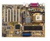
components Before you install the motherboard, learn about its major components and available features to facilitate the installation and future upgrades. Refer to the succeeding pages for the component descriptions. 1 23 4 5 6 7 - Asus P4PE-X TE | P4PE-X/TE User Manual - Page 15
floppy disk drive, a multi-mode parallel port, two standard compatible UARTs, and a Flash ROM interface. 13 PCI slots. These six 32-bit PCI 2.2 expansion slots support bus master PCI cards like SCSI or LAN cards with 133MB/s maximum throughput. ASUS P4PE-X/TE motherboard user guide 1-5 - Asus P4PE-X TE | P4PE-X/TE User Manual - Page 16
AC'97 CODEC that allows 6-channel audio playback. The audio CODEC provides six DAC channels for 5.1 surround sound, S/PDIF output, AUX and Line In stereo inputs, integrated headphone amplifier, greater than 90dB dynamic range, and stereo Mic PREAMP support. 15 LAN controller. The Realtek® RTC8100C - Asus P4PE-X TE | P4PE-X/TE User Manual - Page 17
AUX1 PCI3 PCI4 PCI5 PCI6 01 23 45 Intel I/O Controller Hub (ICH4) ® CR2032 3V Lithium Cell CMOS Power CLRTC ASUS ASIC with Hardware Monitor SB_PWR1 CHASSIS1 2Mbit Firmware Hub Super I/O IDE_LED1 FP_AUDIO1 USB_56 GAME1 PANEL1 30.5cm (12.0in) ASUS P4PE-X/TE motherboard user guide 1-7 - Asus P4PE-X TE | P4PE-X/TE User Manual - Page 18
before you install motherboard components or change any motherboard settings. 1. Unplug the power cord from the wall socket before touching any component or plugging in any motherboard component. ® P4PE-X/TE P4PE-X/TE Onboard LED SB_PWR1 ON Standby Power OFF Powered Off 1-8 - Asus P4PE-X TE | P4PE-X/TE User Manual - Page 19
in the image below. 1.7.2 Screw holes Place seven (7) screws into the holes indicated by circles to secure the motherboard to the chassis. Do not overtighten the screws! Doing so may damage the motherboard. Place this side towards the rear of the chassis ASUS P4PE-X/TE motherboard user guide 1-9 - Asus P4PE-X TE | P4PE-X/TE User Manual - Page 20
.intel.com/ info/hyperthreading. To use the Hyper-Threading Technology on this motherboard: 1. Install a Pentium 4 CPU that supports Hyper-Threading Technology. 2. Power up the system and enter BIOS Setup. Under the Boot Menu, make sure that the item Hyper-Threading Technology is set to Enabled. The - Asus P4PE-X TE | P4PE-X/TE User Manual - Page 21
socket lever to secure the CPU. The lever clicks on the side tab to indicate that it is locked. 6. Install a CPU heatsink and fan following the instructions that came with the heatsink package. 7. Connect the CPU fan cable to the CPU_FAN1 connector on the motherboard. ASUS P4PE-X/TE motherboard user - Asus P4PE-X TE | P4PE-X/TE User Manual - Page 22
to use a PC3200 (400MHz) DDR module, you need to install a CPU with 800MHz FSB. Without an 800MHz FSB CPU, the DDR module can only run at 333MHz or lower frequency. ® P4PE-X/TE 80 Pins 104 Pins P4PE-X/TE 184-Pin DDR DIMM Sockets 1.9.1 Memory configurations You may install any DDR DIMMs with 64MB - Asus P4PE-X TE | P4PE-X/TE User Manual - Page 23
DIMM notch 2. Align a DIMM on the socket such that the notch on the DIMM matches the break on the socket. 3. Firmly insert the DIMM into the socket until the retaining clips snap back in place and the DIMM is properly seated. Unlocked Retaining Clip ASUS P4PE-X/TE motherboard user guide 1-13 - Asus P4PE-X TE | P4PE-X/TE User Manual - Page 24
card following the instructions that came with the chassis. NOTE: The AGP slot supports only 1.5V AGP cards. 2. Turn on the system and change the necessary BIOS settings, if any. See Chapter 2 for BIOS information. 3. Assign an IRQ to the card. Refer to the tables below. 4. Install the drivers - Asus P4PE-X TE | P4PE-X/TE User Manual - Page 25
need to clear the RTC when the system hangs due to overclocking. For system failure due to overclocking, use the C.P.R. (CPU Parameter Recall) feature. Shut down and reboot the system so BIOS can automatically reset parameter settings to default values. ASUS P4PE-X/TE motherboard user guide 1-15 - Asus P4PE-X TE | P4PE-X/TE User Manual - Page 26
or in sleep mode. USBPW12 12 23 ® P4PE-X/TE +5V (Default) +5VSB USBPW34 USBPW56 12 23 +5V P4PE-X/TE USB Device Wake Up (Default) +5VSB 1.12 Connectors This section describes and illustrates the internal connectors on the motherboard. 1. Hard disk activity LED (2-pin IDE_LED1) This - Asus P4PE-X TE | P4PE-X/TE User Manual - Page 27
end to the floppy drive. (Pin 5 is removed to prevent incorrect insertion when using ribbon cables with pin 5 plug). FLOPPY1 ® P4PE-X/TE NOTE: Orient the red markings on the floppy ribbon cable to PIN 1. PIN 1 P4PE-X/TE Floppy Disk Drive Connector ASUS P4PE-X/TE motherboard user guide 1-17 - Asus P4PE-X TE | P4PE-X/TE User Manual - Page 28
settings. BIOS supports specific device bootup sound output. Connect one end of the audio cable to the S/PDIF Out connector on the motherboard, and the other end to the S/PDIF module. The S/PDIF module is purchased separately. SPDIF1 +5V SPDIFOUT GND ® P4PE-X/TE 1-18 P4PE-X/TE Digital Audio - Asus P4PE-X TE | P4PE-X/TE User Manual - Page 29
, AUX1) These connectors allow you to receive stereo audio input from sound sources such as a CD-ROM, TV tuner, or MPEG card. ® P4PE-X/TE CD1(Black) AUX1 (White) Left Audio Channel Ground Ground Right Audio Channel P4PE-X/TE Internal Audio Connectors ASUS P4PE-X/TE motherboard user guide 1-19 - Asus P4PE-X TE | P4PE-X/TE User Manual - Page 30
CPU_FAN1 CHA_FAN1 Rotation +12V GND P4PE-X/TE 12-Volt Fan Connectors 9. USB header (10-1 pin USB_56) If the USB ports on the rear panel are inadequate, a USB header is available for additional USB ports. The USB header complies with USB 2.0 specification that supports up to 480 Mbps connection - Asus P4PE-X TE | P4PE-X/TE User Manual - Page 31
game pad for playing games, and MIDI devices for playing or editing audio files. The USB2.0/GAME module is purchased separately. ® P4PE-X/TE P4PE-X/TE Game Connector +5V J1B2 J1CY GND GND J1CX J1B1 +5V GAME1 1 MIDI_IN J2B2 J2CY MIDI_OUT J2CX J2B1 +5V ASUS P4PE-X/TE motherboard user guide 1-21 - Asus P4PE-X TE | P4PE-X/TE User Manual - Page 32
P4PE-X/TE Reset SW SMI Lead ATX Power Switch* * Requires an ATX power supply. P4PE-X/TE (2-pin SMI) This 2-pin connector allows you to manually place the system into a suspend mode, or and SLEEP, or ON and SOFT OFF, depending on the BIOS or OS settings. Pressing the power switch while in the - Asus P4PE-X TE | P4PE-X/TE User Manual - Page 33
Chapter 2 This chapter tells how to change system settings through the BIOS Setup menus. Detailed descriptions of the BIOS parameters are also provided. BIOS information - Asus P4PE-X TE | P4PE-X/TE User Manual - Page 34
EZ Flash V1.00 Copyright (C) 2003, ASUSTeK COMPUTER INC. [Onboard BIOS Information] BIOS Version : ASUS P4PE-X/TE ACPI BIOS Revision 1002 BIOS Model : P4PE-X/TE BIOS Built Date : 10/06/03 Please Enter File Name for NEW BIOS: _ *Note: EZ Flash will copy file from A:\, Press [ESC] to reboot The - Asus P4PE-X TE | P4PE-X/TE User Manual - Page 35
BIOS area. DO NOT shutdown or reset the system while updating the BIOS area! Doing so may cause system boot failure. 8. When the update process is done, the message, "Press a key to reboot" appears. Press any key to reboot the system with the new BIOS. ASUS P4PE-X/TE motherboard user guide 2-3 - Asus P4PE-X TE | P4PE-X/TE User Manual - Page 36
must specify "Floppy" as the first item in the boot sequence. 4. In DOS mode, type A:\AFLASH to run AFLASH. If the word "unknown" appears after Flash Memory:, the memory chip is either not programmable or is not supported by the ACPI BIOS and therefore, cannot be programmed by the Flash - Asus P4PE-X TE | P4PE-X/TE User Manual - Page 37
>. 4. At the Main Menu, type 2 then press . The Update BIOS Including Boot Block and ESCD screen appears. 5. Type the filename of your new BIOS and the path, for example, A:\XXX- XX.XXX, then press . To cancel this operation, press . ASUS P4PE-X/TE motherboard user guide 2-5 - Asus P4PE-X TE | P4PE-X/TE User Manual - Page 38
boot problems. Just repeat the process, and if the problem persists, load the original BIOS file you saved to the boot disk. If the Flash Memory Writer utility is not able to successfully update a complete BIOS file, the system may not boot. If this happens, call the ASUS service center for support - Asus P4PE-X TE | P4PE-X/TE User Manual - Page 39
the BIOS! Doing so may cause system boot failure! 4. When the BIOS update process is complete, reboot the system. The recovered BIOS may not be the latest BIOS version for this motherboard. Visit the ASUS website (www.asus.com) to download the latest BIOS file. ASUS P4PE-X/TE motherboard user guide - Asus P4PE-X TE | P4PE-X/TE User Manual - Page 40
long beep followed by three short beeps High frequency beeps when system is working Meaning No error during POST No DRAM installed or detected Video card not found or video card memory bad CPU overheated; System running at a lower frequency 2-8 Chapter 2: BIOS information - Asus P4PE-X TE | P4PE-X/TE User Manual - Page 41
default system device used to locate and load the Operating System. Use this menu to exit the current menu or to exit the Setup program. To access the menu bar items, press the right or left arrow key on the keyboard until the desired item is highlighted. ASUS P4PE-X/TE motherboard user guide 2-9 - Asus P4PE-X TE | P4PE-X/TE User Manual - Page 42
its Setup Defaults Saves changes and exits Setup General help In addition to the Item Specific Help window, the BIOS setup program also provides a General Help screen. You may launch this screen from any menu by simply pressing or the + combination. The General Help screen lists the - Asus P4PE-X TE | P4PE-X/TE User Manual - Page 43
appear in the Item Specific Help window located to the right of each menu. This window displays the help text for the currently highlighted field. 2.3 Main Menu When you enter the > or + keys to move between the month, day, and year fields. ASUS P4PE-X/TE motherboard user guide 2-11 - Asus P4PE-X TE | P4PE-X/TE User Manual - Page 44
on how to update the BIOS. Halt On [All Errors] This field specifies the types of errors that will cause the system to halt. Configuration options: [All Errors] [No Error] [All but Keyboard] [All but Disk] [All but Disk/Keyboard] Installed Memory [XXX MB] This field automatically displays the amount - Asus P4PE-X TE | P4PE-X/TE User Manual - Page 45
for the remaining fields on this sub-menu. If automatic detection fails, this may be User Type HDD] Manually enter the number of cylinders, heads and sectors per track for the drive. Refer to the drive documentation or on the drive label for this information. ASUS P4PE-X/TE motherboard user guide - Asus P4PE-X TE | P4PE-X/TE User Manual - Page 46
After making your selections on this sub-menu, press the key to return to the Main menu. When the Main menu appears, the hard disk drive field [User Type HDD] and the Translation Method field to [Manual]. CHS Capacity This field shows the drive's maximum CHS capacity as calculated by the BIOS - Asus P4PE-X TE | P4PE-X/TE User Manual - Page 47
data integrity for compatible IDE devices. Set to [Disabled] to suppress Ultra DMA capability. To make changes to this field, set the Type field to [User Type HDD]. Configuration options: [0] [1] [2] [3] [4] [5] [Disabled] 2.3.2 Keyboard Features ASUS P4PE-X/TE motherboard user guide 2-15 - Asus P4PE-X TE | P4PE-X/TE User Manual - Page 48
] 2.4 Advanced Menu CPU Speed [Manual] This field allows you to select the internal frequency of the CPU. If you use an 800FSB CPU and 400MHz DDR CPU Frequency (MHz) to match the speed of the CPU. The item CPU Frequency Multiple is accessible only if you have an unlocked processor. If your processor - Asus P4PE-X TE | P4PE-X/TE User Manual - Page 49
[Enabled] This item allows you to enable or disable the processor Hyper-Threading Technology. Configuration options: [Disabled] [Enabled] The item Hyper-Threading Technology appears only if you installed an Intel Pentium 4 CPU that supports this feature. ASUS P4PE-X/TE motherboard user guide 2-17 - Asus P4PE-X TE | P4PE-X/TE User Manual - Page 50
, IRQ12 can be used for expansion cards. When you set this field to [Enabled], BIOS reserves IRQ12, whether or not a PS/2 mouse is detected at startup. Configuration options: [Enabled] [Auto] USB Legacy Support [Auto] This motherboard supports Universal Serial Bus (USB) devices. The default of [Auto - Asus P4PE-X TE | P4PE-X/TE User Manual - Page 51
SPD] This parameter allows you to set the optimal timings for items 2-5, depending on the memory modules that you are using. The default setting is [By SPD], which configures items 2-5 for DDR SDRAM parameters. Configuration options: [8T] [7T] [6T] [5T] ASUS P4PE-X/TE motherboard user guide 2-19 - Asus P4PE-X TE | P4PE-X/TE User Manual - Page 52
encounter any problems with the Turbo memory of the processor. It can greatly improve the display speed by caching the display data. You must set this to UC (uncacheable) if your display card does not support this feature, otherwise the system may not boot. Configuration options: [UC] [USWC] Memory - Asus P4PE-X TE | P4PE-X/TE User Manual - Page 53
frees the PCI bus when the CPU is accessing 8-bit ISA cards. This process normally consumes about 50-60 PCI clocks without PCI delayed transaction. Set this field to [Disabled] when using ISA cards Configuration options: [Disabled] [378H/IRQ7] [278H/IRQ5] ASUS P4PE-X/TE motherboard user guide 2-21 - Asus P4PE-X TE | P4PE-X/TE User Manual - Page 54
Parallel Port Mode above. Configuration options: [1] [3] Onboard AC97 Audio Controller [Auto] [Auto] allows the BIOS to detect whether you are using any audio device. If an audio device is detected, the onboard audio controller is enabled; if no audio device is detected, the controller is disabled - Asus P4PE-X TE | P4PE-X/TE User Manual - Page 55
LAN controller. Configuration options: [Disabled] [Enabled] Onboard LAN Boot ROM [Disabled] (appears on LAN models only) This field allows you to enable or disable the option ROM in the onboard LAN controller chipset. Configuration options: [Disabled] [Enabled] ASUS P4PE-X/TE motherboard user guide - Asus P4PE-X TE | P4PE-X/TE User Manual - Page 56
legacy ISA card that requires a unique IRQ and you are NOT using ICU. Configuration options: [No/ICU] [Yes] 2.5 Power Menu The Power menu allows you to reduce power consumption. This feature turns off the video display and shuts down the hard disk after a period of inactivity. 2-24 Chapter 2: BIOS - Asus P4PE-X TE | P4PE-X/TE User Manual - Page 57
menu. The [User BIOS to control the video display card if it supports ACPI Suspend-to-RAM feature. To support this feature, the +5VSB of the power supply should have the capacity to provide more than 720mA current. Configuration options: [Disabled] [Enabled] ASUS P4PE-X/TE motherboard user guide - Asus P4PE-X TE | P4PE-X/TE User Manual - Page 58
an external modem off and then back on while the computer is off causes an initialization string that turns the system power on. 2-26 Chapter 2: BIOS information - Asus P4PE-X TE | P4PE-X/TE User Manual - Page 59
LAN or modem card. This feature requires an ATX power supply that provides at least 1A on the +5VSB lead. Configuration options: [Disabled] [Enabled] Power On By PS/2 Keyboard [Space Bar] This parameter allows you to use specific ] [Everyday] [By Date] ASUS P4PE-X/TE motherboard user guide 2-27 - Asus P4PE-X TE | P4PE-X/TE User Manual - Page 60
CPU Temperature [xxxC/xxxF] The onboard hardware monitor automatically detects and displays the motherboard and CPU temperatures. CPU CPU and chassis fan speeds in rotations per minute (RPM). If any of the fans is not connected to the motherboard, the specific menu for details". You will then - Asus P4PE-X TE | P4PE-X/TE User Manual - Page 61
slots instead of using the BIOS. When [Yes] is selected, interrupts may be reassigned by the OS. If you installed a non-PnP OS or if you want to prevent reassigning of interrupt settings, keep the default setting [No]. Configuration options: [No] [Yes] ASUS P4PE-X/TE motherboard user guide 2-29 - Asus P4PE-X TE | P4PE-X/TE User Manual - Page 62
[No] [Yes] Boot Virus Detection [Enabled] This field allows you to set boot virus detection, ensuring a virus-free boot sector. The system halts time. Configuration options: [Disabled] [Enabled] Boot Up Floppy Seek [Enabled] When enabled, the BIOS will seek the floppy disk drive to determine - Asus P4PE-X TE | P4PE-X/TE User Manual - Page 63
finished making your selections, choose this option from the Exit menu to ensure the values you selected are saved to the other than system date, system time, and password, the BIOS asks for a confirmation before exiting. Load Setup Defaults This option ASUS P4PE-X/TE motherboard user guide 2-31 - Asus P4PE-X TE | P4PE-X/TE User Manual - Page 64
2-32 Chapter 2: BIOS information - Asus P4PE-X TE | P4PE-X/TE User Manual - Page 65
Chapter 3 This chapter describes the contents of the support CD that comes with the motherboard package. Software support - Asus P4PE-X TE | P4PE-X/TE User Manual - Page 66
the motherboard features. The contents of the support CD are subject to change at any time without notice. Visit the ASUS website for updates. 3.2.1 Running the support CD To begin using the support CD, simply insert the CD into your CD-ROM drive. The CD automatically displays the Drivers menu if - Asus P4PE-X TE | P4PE-X/TE User Manual - Page 67
to activate the 6-channel audio features. USB 2.0 Driver This item installs the USB 2.0 driver to support your USB devices. Realtek RTL8001C 10/100M LAN Drivers This item installs the Realtek® RTL8001C drivers to support 10BASE-T/100BASETX networking. ASUS P4PE-X/TE motherboard user guide 3-3 - Asus P4PE-X TE | P4PE-X/TE User Manual - Page 68
the motherboard supports. ASUS PC Probe This smart utility monitors the fan speed, CPU temperature, and system voltages, and alerts you on any detected problems. This utility helps you keep your computer at a healthy operating condition. Install ASUS Update This program allows you to download the - Asus P4PE-X TE | P4PE-X/TE User Manual - Page 69
3.2.4 ASUS Contact Information Clicking the ASUS Contact Information tab displays as stated. You may also find this information on page viii of this user guide. ASUS P4PE-X/TE motherboard user guide 3-5 - Asus P4PE-X TE | P4PE-X/TE User Manual - Page 70
3-6 Chapter 3: Software support
-
 1
1 -
 2
2 -
 3
3 -
 4
4 -
 5
5 -
 6
6 -
 7
7 -
8
-
9
-
10
-
11
-
12
-
13
-
14
-
15
-
16
-
17
-
18
-
19
-
20
-
21
-
22
-
23
-
24
-
25
-
26
-
27
-
28
-
29
-
30
-
31
-
32
-
33
-
34
-
35
-
36
-
37
-
38
-
39
-
40
-
41
-
42
-
43
-
44
-
45
-
46
-
47
-
48
-
49
-
50
-
51
-
52
-
53
-
54
-
55
-
56
-
57
-
58
-
59
-
60
-
61
-
62
-
63
-
64
-
65
-
66
-
67
-
68
-
69
-
70
 |
 |

Motherboard
P4PE-X/TE
User Guide