Asus P4SP-MX SE P4SP-MX SE English User Manual E1676a
Asus P4SP-MX SE Manual
 |
View all Asus P4SP-MX SE manuals
Add to My Manuals
Save this manual to your list of manuals |
Asus P4SP-MX SE manual content summary:
- Asus P4SP-MX SE | P4SP-MX SE English User Manual E1676a - Page 1
Motherboard P4SP-MX SE User Guide - Asus P4SP-MX SE | P4SP-MX SE English User Manual E1676a - Page 2
INC. ("ASUS"). Product warranty or service will not be extended if: (1) the product is repaired, modified or altered, unless such repair, modification of alteration is authorized in writing by ASUS; or (2) the serial number of the product is defaced or missing. ASUS PROVIDES THIS MANUAL "AS IS - Asus P4SP-MX SE | P4SP-MX SE English User Manual E1676a - Page 3
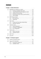
information vi P4SP-MX SE specification summary vii About this guide viii Chapter 1: Product introduction 1.1 Welcome 1-2 1.2 Package contents 1-2 1.3 Special features 1-2 1.3.1 Product highlights 1-2 1.3.2 ASUS unique features 1-4 1.4 Before you proceed 1-5 1.5 Motherboard overview - Asus P4SP-MX SE | P4SP-MX SE English User Manual E1676a - Page 4
Chapter 2: BIOS information 2.1 Managing and updating your BIOS 2-2 2.1.1 2.1.2 2.1.3 2.1.4 2.1.5 Creating a bootable floppy disk 2-2 Using ASUS EZ Flash to update the BIOS 2-3 Using the AFLASH utility 2-4 Recovering the BIOS with CrashFree BIOS .......... 2-6 ASUS Update 2-7 2.2 BIOS Setup - Asus P4SP-MX SE | P4SP-MX SE English User Manual E1676a - Page 5
and, if not installed and used in accordance with manufacturer's instructions, may cause harmful interference to radio communications. However, there is reception, which can be determined by turning the equipment off and on, the user is encouraged to try to correct the interference by one or more of - Asus P4SP-MX SE | P4SP-MX SE English User Manual E1676a - Page 6
supply is broken, do not try to fix it by yourself. Contact a qualified service technician or your retailer. Operation safety • Before installing the motherboard and adding devices on it, carefully read all the manuals that came with the package. • Before using the product, make sure all cables - Asus P4SP-MX SE | P4SP-MX SE English User Manual E1676a - Page 7
P4SP-MX SE specification summary* CPU Chipset Front Side Bus (FSB) Memory Expansion slots VGA Storage Audio LAN Special features Rear panel I/O Internal I/O BIOS features Socket 478 for Intel® Pentium® 4/Celeron processor Intel® Hyper-Threading technology ready New power design for next generation - Asus P4SP-MX SE | P4SP-MX SE English User Manual E1676a - Page 8
P4SP-MX SE specification summary Industry standard Manageability Form Factor Support CD contents PCI 2.2, USB 2.0/1.1 WOL/WOR by PME, DMI 2.0, WfM 2.0 Micro-ATX form factor: 9.6 in x 9.6 in (24.5 cm x 24.5 cm) Device drivers ASUS PC Probe ASUS LiveUpdate ASUS Screensaver Adobe Acrobat Reader Trend - Asus P4SP-MX SE | P4SP-MX SE English User Manual E1676a - Page 9
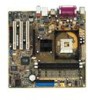
Chapter 1 This chapter describes the features of the motherboard. It includes brief descriptions of the motherboard components, and illustrations of the layout, jumper settings, and connectors. Product introduction - Asus P4SP-MX SE | P4SP-MX SE English User Manual E1676a - Page 10
P4SP-MX SE package for the following items. ASUS P4SP-MX SE motherboard Micro-ATX form factor: 9.6 in x 9.6 in (24.5 cm x 24.5 cm) ASUS P4SP-MX SE series support CD 9-pin COM cable 80-conductor UltraDMA cable Ribbon cable for a 3.5-inch floppy drive I/O shield Bag of extra jumper caps User Guide - Asus P4SP-MX SE | P4SP-MX SE English User Manual E1676a - Page 11
Mbps) allows faster Internet connection, interactive gaming, and simultaneous running of high-speed peripherals. USB 2.0 is backward compatible with USB 1.1. See pages 1-17 and 1-20. ASUS P4SP-MX SE motherboard user guide 1-3 - Asus P4SP-MX SE | P4SP-MX SE English User Manual E1676a - Page 12
a virus. Unlike other competing vendors' products, ASUS motherboards now enable users to enjoy this protection feature without the need to pay for an optional ROM. See page 2-6. ASUS EZ Flash BIOS With the ASUS EZ Flash, you can easily update the system BIOS even before loading the operating system - Asus P4SP-MX SE | P4SP-MX SE English User Manual E1676a - Page 13
should shut down the system and unplug the power cable before removing or plugging in any motherboard component. The illustration below shows the location of the onboard LED. ® P4SP-MX SE P4SP-MX SE Onboard LED SB_PWR1 ON Standby Power OFF Powered Off ASUS P4SP-MX SE motherboard user guide 1-5 - Asus P4SP-MX SE | P4SP-MX SE English User Manual E1676a - Page 14
, 184-pin module) SEC_IDE1 PRI_IDE1 24.4cm (9.6in) 1.5 Motherboard overview 1.5.1 Motherboard layout 24.4cm (9.6in) PS/2KBMS T: Mouse B: Keyboard PCI Slot 1 ® PCI Slot 2 P4SP-MX SE PCI Slot 3 FLOPPY1 USB_56 SiS962L MuTLOL Media I/0 USBPWR_56 Super I/O CLRTC1 2Mbit Flash BIOS GAME1 - Asus P4SP-MX SE | P4SP-MX SE English User Manual E1676a - Page 15
in the image below. 1.5.3 Screw holes Place eight (8) screws into the holes indicated by circles to secure the motherboard to the chassis. Do not overtighten the screws! Doing so may damage the motherboard. Place this side towards the rear of the chassis ASUS P4SP-MX SE motherboard user guide 1-7 - Asus P4SP-MX SE | P4SP-MX SE English User Manual E1676a - Page 16
a specific corner of the CPU socket. ® P4SP-MX SE Gold Arrow P4SP-MX SE CPU Socket 478 Incorrect installation of the CPU into the socket may bend the pins and severely damage the CPU! Notes on Intel® Hyper-Threading Technology • Hyper-Threading Technology is supported under Windows XP and Linux - Asus P4SP-MX SE | P4SP-MX SE English User Manual E1676a - Page 17
the CPU. The lever clicks on the side tab to indicate that it is locked. 6. Install a CPU heatsink and fan following the instructions that came with the heatsink package. 7. Connect the CPU fan cable to the CPU_FAN1 connector on the motherboard. Gold Mark ASUS P4SP-MX SE motherboard user guide - Asus P4SP-MX SE | P4SP-MX SE English User Manual E1676a - Page 18
the DDR DIMM sockets. 104 Pins ® P4SP-MX SE P4SP-MX SE 184-pin DDR DIMM sockets 80 Pins • Make sure to unplug the power supply before adding or removing DIMMs or other system components. Failure to do so may cause severe damage to both the motherboard and the components. • When installing long - Asus P4SP-MX SE | P4SP-MX SE English User Manual E1676a - Page 19
DIMM. 1. Simultaneously press the retaining clips outward to unlock the DIMM. Support the DIMM lightly with your fingers when pressing the retaining clips. The DIMM might get damaged when it flips out with extra force. 2. Remove the DIMM from the socket. ASUS P4SP-MX SE motherboard user guide 1-11 - Asus P4SP-MX SE | P4SP-MX SE English User Manual E1676a - Page 20
slots and the expansion cards that they support. Make sure to unplug the power cord before adding or removing expansion cards. Failure to do so may cause you physical injury and damage motherboard and change the necessary BIOS settings, if any. See Chapter 2 for information on BIOS setup. 2. Assign - Asus P4SP-MX SE | P4SP-MX SE English User Manual E1676a - Page 21
-- -- -- When using PCI cards on shared slots, ensure that the drivers support "Share IRQ" or that the cards do not need IRQ assignments. Otherwise, conflicts will arise between the two PCI groups, making the system unstable and the card inoperable. ASUS P4SP-MX SE motherboard user guide 1-13 - Asus P4SP-MX SE | P4SP-MX SE English User Manual E1676a - Page 22
+1.5V specification. Note the notches on the card golden fingers to ensure that they fit the AGP slot on the motherboard. This motherboard does not support 3.3V AGP cards. Install only +1.5V AGP cards. ® P4SP-MX SE P4SP-MX SE Accelerated Graphics Port (AGP ) 1-14 Chapter 1: Product introduction - Asus P4SP-MX SE | P4SP-MX SE English User Manual E1676a - Page 23
to re-enter data. Except when clearing the RTC RAM, never remove the cap on CLRTC1 jumper default position. Removing the cap will cause system boot failure! ® P4SP-MX SE CLRTC1 12 23 Normal (Default) Clear CMOS P4SP-MX SE Clear RTC RAM setting ASUS P4SP-MX SE motherboard user guide 1-15 - Asus P4SP-MX SE | P4SP-MX SE English User Manual E1676a - Page 24
wake up from S3 sleep mode (no power to CPU, DRAM in slow refresh, power supply in reduced power not all computers have the appropriate power supply to support this feature. The USBPW_12 and USBPW_34 jumpers are for mode. USBPWR_34 USBPWR_12 12 23 ® P4SP-MX SE P4SP-MX SE USB device wake up +5V - Asus P4SP-MX SE | P4SP-MX SE English User Manual E1676a - Page 25
USB 2.0 devices. 9. VGA port. This port connects a VGA compatible monitor. 10. S/PDIF port. This port connects S/PDIF devices that provide 6-channel surround sound and 3D audio. 11. PS/2 keyboard port. This purple connector is for a PS/2 keyboard. ASUS P4SP-MX SE motherboard user guide 1-17 - Asus P4SP-MX SE | P4SP-MX SE English User Manual E1676a - Page 26
on the IDE ribbon cable to PIN 1 SEC_IDE1 PRI_IDE1 ® P4SP-MX SE P4SP-MX SE IDE connectors PIN 1 PIN 1 2. Floppy disk drive connector (34-1 pin FLOPPY1) This connector supports the provided floppy drive ribbon cable. After connecting one end to the motherboard, connect the other end to the floppy - Asus P4SP-MX SE | P4SP-MX SE English User Manual E1676a - Page 27
ATXPWR connector, this motherboard requires that you connect the 4-pin ATX +12V power plug to provide sufficient power to the CPU. Make sure that audio cable. AGND +5VA BLINE_OUT_R BLINE_OUT_L ® P4SP-MX SE FP_AUDIO1 P4SP-MX SE Front panel audio connector ASUS P4SP-MX SE motherboard user guide - Asus P4SP-MX SE | P4SP-MX SE English User Manual E1676a - Page 28
. Lack of sufficient air flow within the system may damage the motherboard components. These are not jumpers! DO NOT place jumper caps on the fan connectors! CPU_FAN1 GND +12V Rotation ® P4SP-MX SE GND +12V Rotation CHA_FAN1 P4SP-MX SE Fan connectors 6. USB header (10-1 pin USB56) If the USB - Asus P4SP-MX SE | P4SP-MX SE English User Manual E1676a - Page 29
or a game pad for playing games, and MIDI devices for playing or editing audio files. +5V J1B2 J1CY GND GND J1CX J1B1 +5V MIDI_IN J2B2 J2CY MIDI_OUT J2CX J2B1 +5V ® P4SP-MX SE P4SP-MX SE Game connector GAME1 The GAME module is purchased separately. ASUS P4SP-MX SE motherboard user guide 1-21 - Asus P4SP-MX SE | P4SP-MX SE English User Manual E1676a - Page 30
serial port module to this connector, then install the module into a slot opening at the front or back of the system chassis. COM1 PIN 1 ® P4SP-MX SE P4SP-MX SE Serial Interrupt Lead (2-pin SMI) This 2-pin connector allows you to manually place the system into a suspend mode, or "green" mode, - Asus P4SP-MX SE | P4SP-MX SE English User Manual E1676a - Page 31
Pressing the power switch turns the system between ON and SLEEP, or ON and SOFT OFF, depending on the BIOS or OS settings. Pressing the power switch while in the ON mode for more than 4 seconds turns the secondary IDE connector cause this LED to light up. ASUS P4SP-MX SE motherboard user guide 1-23 - Asus P4SP-MX SE | P4SP-MX SE English User Manual E1676a - Page 32
1-24 Chapter 1: Product introduction - Asus P4SP-MX SE | P4SP-MX SE English User Manual E1676a - Page 33
Chapter 2 This chapter tells how to change system settings through the BIOS Setup menus. Detailed descriptions of the BIOS parameters are also provided. BIOS information - Asus P4SP-MX SE | P4SP-MX SE English User Manual E1676a - Page 34
utilities. • Visit the ASUS website and download the latest BIOS file for this motherboard using the ASUS Update utility. 2.1.1 Creating a bootable floppy disk 1. Do either one of the following to create a bootable floppy disk. DOS environment Insert a 1.44 MB floppy disk into the drive. At the DOS - Asus P4SP-MX SE | P4SP-MX SE English User Manual E1676a - Page 35
the system while updating the BIOS! Doing so may cause system boot failure! User recovery requested. Starting BIOS recovery... Checking for floppy... Floppy found! Reading file "P4SPMXSE.BIN". Completed. Start flashing... Flashed successfully. Rebooting. ASUS P4SP-MX SE motherboard user guide 2-3 - Asus P4SP-MX SE | P4SP-MX SE English User Manual E1676a - Page 36
motherboard BIOS To copy the original motherboard BIOS file: 1. Copy the AFLASH utility from the support CD to the boot disk you created. AFLASH does not work in the DOS prompt within Windows®, and does not work with certain memory drivers that may be loaded when you boot from the hard drive - Asus P4SP-MX SE | P4SP-MX SE English User Manual E1676a - Page 37
the update. 7. The utility starts updating the BIOS. The boot block is automatically updated only when necessary. This minimizes the possibility of boot problems in case of update failures. When updating is done, the message "Flashed Successfully" appears. ASUS P4SP-MX SE motherboard user guide - Asus P4SP-MX SE | P4SP-MX SE English User Manual E1676a - Page 38
slots before rebooting the computer. On motherboards with onboard VGA, such as the P4SP-MX SE, you will not see the screen display when the BIOS crashes even if you reboot the computer. • Prepare the floppy disk that contains the motherboard BIOS (P4SPMXSE.BIN) before proceeding with the BIOS update - Asus P4SP-MX SE | P4SP-MX SE English User Manual E1676a - Page 39
system. To update the BIOS using the ASUS Update: 1. Launch the utility from the Windows desktop by clicking Start > Programs > ASUS > ASUSUpdate > ASUSUpdate. The ASUS Update initial screen appears. 2. Select your desired update method, then click Next. ASUS P4SP-MX SE motherboard user guide 2-7 - Asus P4SP-MX SE | P4SP-MX SE English User Manual E1676a - Page 40
. Click Next. 4. From the FTP site, select the BIOS version that you wish to download. Click Next. 5. Follow the instructions on the succeeding screens to complete the update process. If you selected the option to update the BIOS from a file, a window pops up prompting you to locate the file. Select - Asus P4SP-MX SE | P4SP-MX SE English User Manual E1676a - Page 41
motherboard supports a programmable Flash ROM that you can update using the provided utility described in section "2.1 Managing and updating your BIOS." Use the BIOS Setup program when you are installing a motherboard until the desired item is highlighted. ASUS P4SP-MX SE motherboard user guide 2-9 - Asus P4SP-MX SE | P4SP-MX SE English User Manual E1676a - Page 42
field Resets the current screen to its Setup Defaults Saves changes and exits Setup General help In addition to the Item Specific Help window, the BIOS setup program also provides a General Help screen. You may launch this screen from any menu by simply pressing or the - Asus P4SP-MX SE | P4SP-MX SE English User Manual E1676a - Page 43
program, note that explanations appear in the Item Specific Help window located to the right of each menu. This window displays the help text for the currently highlighted field. 2.3 + keys to move between the month, day, and year fields. ASUS P4SP-MX SE motherboard user guide 2-11 - Asus P4SP-MX SE | P4SP-MX SE English User Manual E1676a - Page 44
[Disabled] This is required to support older Japanese floppy drives. The Floppy 3 Mode feature allows reading and writing of 1.2MB (as opposed to 1.44MB) on a 3.5-inch diskette. Configuration options: [Disabled] [Enabled] Supervisor Password [Disabled] / User Password [Disabled] These fields allow - Asus P4SP-MX SE | P4SP-MX SE English User Manual E1676a - Page 45
settings may cause the system to fail to recognize the installed hard disk. [User Type HDD] Manually enter the number of cylinders, heads and sectors per track for the drive. Refer to the drive documentation or on the drive label for this information. ASUS P4SP-MX SE motherboard user guide 2-13 - Asus P4SP-MX SE | P4SP-MX SE English User Manual E1676a - Page 46
value. To make changes to this field, set the Type field to [User Type HDD] and the Translation Method field to [Manual]. CHS Capacity This field shows the drive's maximum CHS capacity as calculated by the BIOS based on the drive information you entered. Maximum LBA Capacity This field shows the - Asus P4SP-MX SE | P4SP-MX SE English User Manual E1676a - Page 47
field to [User Type HDD]. Configuration options: [0] [1] [2] [3] [4] [5] [6] [Disabled] 2.3.2 Keyboard Features Boot Up NumLock Status [On] This field enables users to activate the Number Lock function upon system boot. Configuration options: [Off] [On] ASUS P4SP-MX SE motherboard user guide 2-15 - Asus P4SP-MX SE | P4SP-MX SE English User Manual E1676a - Page 48
Advanced menu CPU Speed [Manual] When the motherboard is set to CPU Speed item to [Manual]. This feature tells the clock generator what frequency to send to the system bus and PCI bus. The bus frequency (external frequency) multiplied by the bus multiple equals the CPU speed. 2-16 Chapter 2: BIOS - Asus P4SP-MX SE | P4SP-MX SE English User Manual E1676a - Page 49
or off the CPU Level 2 built-in cache. Configuration options: [Disabled] [Enabled] BIOS Update [Enabled] This field functions as an update loader integrated into the BIOS to supply the setting [Disabled]. Configuration options: [Disabled] [Enabled] ASUS P4SP-MX SE motherboard user guide 2-17 - Asus P4SP-MX SE | P4SP-MX SE English User Manual E1676a - Page 50
items 2 ~ 5 by reading the contents in the SPD (Serial Presence Detect) device. The EEPROM on the memory module stores critical User Defined] [By SPD] The SDRAM parameters (items 2 ~ 5) are user-configurable only when you set the SDRAM Configuration to [User [1T] 2-18 Chapter 2: BIOS information - Asus P4SP-MX SE | P4SP-MX SE English User Manual E1676a - Page 51
set both channels to [Disabled]. Configuration options: [Both] [Primary] [Secondary] [Disabled] IDE Bus Master Support [Enabled] This item controls the IDE Bus Master support for non-Windows® operating systems. Configuration options: [Disabled] [Enabled] ASUS P4SP-MX SE motherboard user guide 2-19 - Asus P4SP-MX SE | P4SP-MX SE English User Manual E1676a - Page 52
floppy disk drive to only read data from a floppy disk. The default setting [R/W] allows both reading and writing data to a floppy disk. Configuration options: [R/W] [Read Only] Onboard Serial Port I/O port. Configuration options: [Disabled] [330H-331H] [300H-301H] 2-20 Chapter 2: BIOS information - Asus P4SP-MX SE | P4SP-MX SE English User Manual E1676a - Page 53
VGA Palette Snoop [Disabled] Some non-standard VGA cards, like graphics accelerators or MPEG video cards, may not show colors properly. Setting this field to [Enabled] corrects this problem. If you are using standard VGA options: [Disabled] [Enabled] ASUS P4SP-MX SE motherboard user guide 2-21 - Asus P4SP-MX SE | P4SP-MX SE English User Manual E1676a - Page 54
[Disabled] This field allows you enable or disable the onboard LAN Boot ROM feature. Configuration options: [Disabled] [Enabled] Onboard AC97 Audio Controller [Auto] This field allows you to disable the onboard AC97 audio controller or set to the default [Auto] for optimum performance. Configuration - Asus P4SP-MX SE | P4SP-MX SE English User Manual E1676a - Page 55
the video off features. The Display Power Management System (DPMS) allows the BIOS to control the video display card if it supports DPMS. Set this option to [Blank Screen] when using monitors that do not support power management or "green" features. ASUS P4SP-MX SE motherboard user guide 2-23 - Asus P4SP-MX SE | P4SP-MX SE English User Manual E1676a - Page 56
as your video-off method. user-configurable field. This feature does not affect SCSI hard drives. Configuration options: [Disabled] [1 Min] [2 Min] [3 Min]...[15 Min] ACPI Suspend To RAM [Disabled] This field allows you to enable or disable the ACPI Suspend-to-RAM feature. To support BIOS information - Asus P4SP-MX SE | P4SP-MX SE English User Manual E1676a - Page 57
on the system through a PCI LAN or modem card. This feature CPU Temperature [XXºC/XXºF] The onboard hardware monitor automatically detects and displays the CPU temperature in degree Celsius. Select [Ignore] to disable the CPU temperature auto-detect function. ASUS P4SP-MX SE motherboard user guide - Asus P4SP-MX SE | P4SP-MX SE English User Manual E1676a - Page 58
CPU, chassis, and power fan speeds in rotations per minute (RPM). If any of the fans is not connected to the motherboard Configuration fields include Removable Devices, IDE Hard Drive, ATAPI CD-ROM, and Other Boot ZIP] IDE Hard Drive This field allows you to select which IDE hard disk drive to use in - Asus P4SP-MX SE | P4SP-MX SE English User Manual E1676a - Page 59
the product IDs of all your connected ATAPI CD-ROM drives. Other Boot Device Select [INT18 Device (Network)] Configuration (PnP) operating system to configure the PCI bus slots instead of using the BIOS. When [Yes] is selected, interrupts may be reassigned ASUS P4SP-MX SE motherboard user guide 2-27 - Asus P4SP-MX SE | P4SP-MX SE English User Manual E1676a - Page 60
saves your selections without exiting the Setup program. You can then return to other menus and make further changes. After you select this option, a confirmation window appears. Select [Yes] to save changes to the non-volatile RAM. 2-28 Chapter 2: BIOS information - Asus P4SP-MX SE | P4SP-MX SE English User Manual E1676a - Page 61
Chapter 3 This chapter describes the contents of the support CD that comes with the motherboard package. Software support - Asus P4SP-MX SE | P4SP-MX SE English User Manual E1676a - Page 62
drivers that enhance the motherboard features. The contents of the support CD are subject to change at any time without notice. Visit the ASUS website for updates. 3.2.1 Running the support CD Place the support CD to your optical drive. The CD automatically displays the Installation Items window - Asus P4SP-MX SE | P4SP-MX SE English User Manual E1676a - Page 63
® Acrobat Reader® V.50. The Acrobat Reader® software is for viewing files saved in Portable Document Format (PDF). Click the button to display other installation items. ASUS P4SP-MX SE motherboard user guide 3-3 - Asus P4SP-MX SE | P4SP-MX SE English User Manual E1676a - Page 64
the general specifications for the P4SP-MX SE motherboard. Browse Support CD Click this item to display the support CD contents. Readme This item displays the support CD contents and a brief description of each in text format. Exit Click this item to close the installation window. Click the button
-
 1
1 -
 2
2 -
 3
3 -
 4
4 -
 5
5 -
 6
6 -
 7
7 -
8
-
9
-
10
-
11
-
12
-
13
-
14
-
15
-
16
-
17
-
18
-
19
-
20
-
21
-
22
-
23
-
24
-
25
-
26
-
27
-
28
-
29
-
30
-
31
-
32
-
33
-
34
-
35
-
36
-
37
-
38
-
39
-
40
-
41
-
42
-
43
-
44
-
45
-
46
-
47
-
48
-
49
-
50
-
51
-
52
-
53
-
54
-
55
-
56
-
57
-
58
-
59
-
60
-
61
-
62
-
63
-
64
 |
 |

Motherboard
P4SP-MX SE
User Guide