Asus P5CR-VM User Guide
Asus P5CR-VM Manual
 |
View all Asus P5CR-VM manuals
Add to My Manuals
Save this manual to your list of manuals |
Asus P5CR-VM manual content summary:
- Asus P5CR-VM | User Guide - Page 1
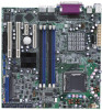
P5CR-VM Motherboard - Asus P5CR-VM | User Guide - Page 2
Product warranty or service will not be extended if: (1) the product is repaired, modified or altered, unless such repair, modification of alteration is authorized in writing by ASUS; or (2) the serial number of the product is defaced or missing. ASUS PROVIDES THIS MANUAL "AS IS" WITHOUT WARRANTY - Asus P5CR-VM | User Guide - Page 3
Typography ix P5CR-VM specifications summary x Chapter 1: Product introduction 1.1 Welcome 1-1 1.2 Package contents 1-1 1.3 Special features 1-2 1.3.1 Product highlights 1-2 1.3.2 Innovative ASUS features 1-4 Chapter 2: Hardware information 2.1 Before you proceed 2-1 2.2 Motherboard overview - Asus P5CR-VM | User Guide - Page 4
setup 4.1 Managing and updating your BIOS 4-1 4.1.1 Creating a bootable floppy disk 4-1 4.1.2 AFUDOS utility 4-2 4.1.3 ASUS EZ Flash utility 4-5 4.1.4 ASUS CrashFree BIOS 2 utility 4-6 4.1.5 ASUS Update utility 4-8 4.2 BIOS setup program 4-11 4.2.1 BIOS menu screen 4-12 4.2.2 Menu bar 4-12 - Asus P5CR-VM | User Guide - Page 5
menu 4-29 4.5.1 ACPI APIC Support 4-29 4.5.2 APM Configuration 4-29 4.5.3 Hardware Monitor 4-31 4.6 Boot menu 4-32 4.6.1 Boot Device Priority 4-32 4.6.2 Boot Settings Configuration 4-33 4.6.3 Security 4-34 4.7 Exit menu 4-36 Appendix: Reference information A.1 P5CR-VM block diagram A-1 v - Asus P5CR-VM | User Guide - Page 6
. This equipment generates, uses and can radiate radio frequency energy and, if not installed and used in accordance with manufacturer's instructions, may cause harmful interference to radio communications. However, there is no guarantee that interference will not occur in a particular installation - Asus P5CR-VM | User Guide - Page 7
Contact a qualified service technician or your retailer. Operation safety • Before installing the motherboard and adding devices on it, carefully read all the manuals that came with . • If you encounter technical problems with the product, contact a qualified service technician or your retailer. vii - Asus P5CR-VM | User Guide - Page 8
you need when installing and configuring the motherboard. How this guide is organized This manual contains the following parts: • Chapter 1: Product introduction This chapter describes the features of the motherboard and the new technology it supports. • Chapter 2: Hardware information This chapter - Asus P5CR-VM | User Guide - Page 9
following symbols used throughout this manual. D A N G E R / W A R N I N G : Information to prevent injury to yourself when trying to complete a task. C A U T I O N : Information to prevent damage to the components when trying to complete a task. I M P O R T A N T : Instructions that you MUST follow - Asus P5CR-VM | User Guide - Page 10
-VM specifications summary CPU Chipset Front Side Bus Memory Expansion slots Storage LAN USB Special features BIOS features Rear panel LGA775 socket for Intel® Pentium® 4 processor with Extended Memory 64-bit Technology (EM64T) Supports Intel® Hyper-Threading Technology Northbridge: Intel® E7221 - Asus P5CR-VM | User Guide - Page 11
P5CR-VM specifications summary Internal connectors Power Requirement Form Factor Support CD contents 1 x Floppy disk drive connector 1x IDE connector 4 x Serial ATA connectors 2 x CPU 25 cm x 25 cm) Device drivers ASUS Live Update utility ASUS System Web-based Management (ASWM®) *Specifications are - Asus P5CR-VM | User Guide - Page 12
xii - Asus P5CR-VM | User Guide - Page 13
This chapter describes the motherboard features and the new technologies it supports. 1Product introduction - Asus P5CR-VM | User Guide - Page 14
Chapter summary 1 1.1 Welcome 1-1 1.2 Package contents 1-1 1.3 Special features 1-2 ASUS P5CR-VM - Asus P5CR-VM | User Guide - Page 15
for the following items. M o t h e r b o a r d ASUS P5CR-VM motherboard Cables Accessory Application CD Documentation 2-in-1 disk drive cable (IDE and floppy disk drive cable) 4 x Serial ATA signal cables 4 x Serial ATA power cables I/O shield ASUS motherboard support CD User guide If any of the - Asus P5CR-VM | User Guide - Page 16
. The motherboard supports the Intel® Pentium® 4 processor with 800/533 MHz Front Side Bus (FSB). The motherboard also supports the Intel® Hyper-Threading technology and is fully compatible with Intel® 04B and 04A processors. See page 2-6 for details. Intel® E7221/Intel® ICH6R chipset The Intel - Asus P5CR-VM | User Guide - Page 17
motherboard fully supports PCI for details. Gigabit LAN solution The motherboard comes with onboard dual Gigabit LAN controllers to provide and 2-28 for details. Temperature, fan, and voltage monitoring The CPU temperature is monitored by the ASIC W83792AD to prevent overheating and ASUS P5CR-VM 1-3 - Asus P5CR-VM | User Guide - Page 18
4-30 for details. ASUS CrashFree BIOS 2 This feature allows you to restore the original BIOS data from the support CD in case when for details. ASUS Update This utility allows you to update the motherboard BIOS through a user-friendly interface. Connect to the Internet then to the ASUS FTP site - Asus P5CR-VM | User Guide - Page 19
This chapter lists the hardware setup procedures that you have to perform when installing system components. It includes description of the jumpers and connectors on the motherboard. 2 Hardware information - Asus P5CR-VM | User Guide - Page 20
Chapter summary 2 2.1 Before you proceed 2-1 2.2 Motherboard overview 2-2 2.3 Central Processing Unit (CPU 2-6 2.4 System memory 2-13 2.5 Expansion slots 2-15 2.6 Jumpers 2-18 2.7 Connectors 2-23 ASUS P5CR-VM - Asus P5CR-VM | User Guide - Page 21
mode. This is a reminder that you should shut down the system and unplug the power cable before removing or plugging in any motherboard component. The illustration below shows the location of the onboard LED. P5CR-VM P5CR-VM Onboard LED SB_PWR1 ON Standby Power OFF Powered Off ASUS P5CR-VM 2-1 - Asus P5CR-VM | User Guide - Page 22
in the image below. 2.2.2 Screw holes Place eight (8) screws into the holes indicated by circles to secure the motherboard to the chassis. Do not overtighten the screws! Doing so can damage the motherboard. Place this side towards the rear of the chassis P5CR-VM 2-2 Chapter 2: Hardware information - Asus P5CR-VM | User Guide - Page 23
Motherboard layout PS/2KBMS KBPWR1 T: Mouse B: Keyboard USB12 USBPW12 ATXPWR1 PSUSMB1 25cm (9.8in) FM_CPU1 CPU_FAN1 COM1 Intel® E7221 LGA775 P5CR-VM TRPWR1 FRNT_FAN2 BMCSOCKET1 FLOPPY1 USB34 USB56 USB78 HDLED1 BMCCONN1 PANEL1 AUX_PANEL1 SB_PWR1 SATA1 SATA2 SATA3 SATA4 ASUS P5CR-VM - Asus P5CR-VM | User Guide - Page 24
Jumpers 1. Clear RTC RAM (CLRTC1) 2. CPU fan mode selection (3-pin FM_CPU1, FM_CPU2) 3. USB device wake-up (3-pin USBPW12, USBPW34, USBPW56 USBPW78) 4. Keyboard and mouse power (3-pin KBPWR1) 5. Gigabit LAN controller setting (3-pin LAN_EN1) 6. Gigabit LAN controller setting (3-pin LAN_EN2) 7. BIOS - Asus P5CR-VM | User Guide - Page 25
PRI_IDE1)) 2-25 3. Serial ATA connectors (7-pin SATA1, SATA2, SATA3, SATA4) 2-26 5. CPU fan connectors (4-pin CPU_FAN1/CPU_FAN2)) 2-27 6. System fan connectors (3-pin REAR_FAN1/REAR_FAN2, FRNT_FAN1/ off button (Yellow 2-pin POWERBTN) • Reset button (Blue 2-pin RESETCON) 2-34 ASUS P5CR-VM 2-5 - Asus P5CR-VM | User Guide - Page 26
2.3 Central Processing Unit (CPU) The motherboard comes with a surface mount LGA775 socket designed for the Intel® Pentium® 4 processor in the 775-land package. • Your boxed Intel® Pentium® 4 LGA775 processor package should come with installation instructions for the CPU, heatsink, and the retention - Asus P5CR-VM | User Guide - Page 27
are installing a CPU. 3. Lift the load lever in the direction of the arrow to CPU over the socket, making sure that the gold triangle is on the bottom-left corner of the socket. The socket alignment key A l i g n m e n t k e y should fit into the CPU notch. Gold triangle mark ASUS P5CR-VM - Asus P5CR-VM | User Guide - Page 28
in only one correct orientation. DO NOT force the CPU into the socket to prevent bending the connectors on the socket and damaging the CPU! Notes on Intel® Hyper-Threading Technology • This motherboard supports Intel® Pentium® 4 CPUs in the 775-land package with Hyper-Threading Technology. • Hyper - Asus P5CR-VM | User Guide - Page 29
heatsink and fan assembly such that the CPU fan cable is closest to the CPU fan connector. Narrow end of the groove Motherboard hole Fastener Make sure to orient each fastener with the narrow end of the groove pointing outward. (The photo shows the groove shaded for emphasis.) ASUS P5CR-VM 2-9 - Asus P5CR-VM | User Guide - Page 30
heatsink and fan assembly in A place. A B A B B A 3. Connect the CPU fan cable to the connectors on the motherboard labeled CPU_FAN1/CPU_FAN2. CPU_FAN1 CPU_FAN1 GND FANPWR2 FANOUT4 CPU_FAN2 CPU_FAN2 FANOUT7 FANPWR3 GND P5CR-VM P5CR-VM CPU fan connectors • Do not forget to connect the - Asus P5CR-VM | User Guide - Page 31
CPU heatsink and fan: 1. Disconnect the CPU fan cable from the connector on the motherboard. 2. Rotate each fastener counterclockwise. 3. Pull up two fasteners at a time in a diagonal sequence to disengage the heatsink B and fan assembly from the A motherboard. A B A B B A ASUS P5CR-VM - Asus P5CR-VM | User Guide - Page 32
4. Carefully remove the heatsink and fan assembly from the motherboard. 5. Rotate each fastener clockwise to ensure correct orientation when reinstalling. The narrow end of the groove should point outward after resetting. (The photo shows the - Asus P5CR-VM | User Guide - Page 33
2.4 System memory 2.4.1 Overview The motherboard comes with four Double Data Rate 2 (DDR2) Dual Inline Memory Modules from the same vendor. • Due to chipset resource allocation, the system may detect less than 4 GB system memory when you installed four 1 GB DDR2 memory modules. ASUS P5CR-VM 2-13 - Asus P5CR-VM | User Guide - Page 34
components. Failure to do so can cause severe damage to both the motherboard and the components. To install a DIMM: 1. Unlock a DIMM socket it fits in only one direction. Do not force a DIMM into a socket to avoid damaging the DIMM. • The DDR2 DIMM sockets do not support DDR DIMMs. DO not install - Asus P5CR-VM | User Guide - Page 35
motherboard drivers for the expansion card. When using PCI cards on shared slots, ensure that the drivers support "Share IRQ" or that the cards do not need IRQ assignments. Otherwise, conflicts will arise between the two PCI groups, making the system unstable and the card inoperable. ASUS P5CR-VM - Asus P5CR-VM | User Guide - Page 36
Keyboard Controller Re-direct to IRQ Processor Primary IDE Channel Secondary IDE Channel * These IRQs are usually available for ISA or PCI devices. IRQ assignments for this motherboard When using PCI cards on shared slots, ensure that the drivers support "Share IRQ" or that the cards do not need - Asus P5CR-VM | User Guide - Page 37
channel card, etc. 2.5.5 PCI Express x1 slot This motherboard supports PCI Express x1 network cards, SCSI cards, and other support cards such as a LAN card, SCSI card, USB card, and other cards that comply with PCI 2.3 specifications. The figure shows a LAN card installed on a PCI slot. ASUS P5CR-VM - Asus P5CR-VM | User Guide - Page 38
-enter data. Except when clearing the RTC RAM, never remove the cap on CLRTC jumper default position. Removing the cap will cause system boot failure! P5CR-LS P5CR-VM Clear RTC RAM CLRTC1 1 2 Normal (Default) 2 3 Clear CMOS 2-18 Chapter 2: Hardware information - Asus P5CR-VM | User Guide - Page 39
+5VSB to wake up from S4 sleep mode (no power to CPU, DRAM power supply in reduced power mode). USBPW12 21 32 +5V (Default) +5VSB P5CR-LS P5CR-VM USB device wake-up USBPW34 21 32 +5V (Default) +5VSB capability (+5VSB) whether under normal condition or in sleep mode. ASUS P5CR-VM 2-19 - Asus P5CR-VM | User Guide - Page 40
supply at least 1A on the +5VSB lead, and a corresponding setting in the BIOS. KBPWR1 21 32 +5V (Default) +5VSB P5CR-LS P5CR-VM Keyboard and mouse power setting 5 . Gigabit LAN controller setting (3-pin LAN_EN1) These jumpers allow you to enable or disable the onboard Broadcom BCM5721 Gigabit - Asus P5CR-VM | User Guide - Page 41
6 . Gigabit LAN controller setting (3-pin LAN_EN2) These jumpers allow you to enable or disable the onboard Broadcom BCM5721 Gigabit LAN controller. Set to pins 1-2 to activate the Gigabit LAN feature. P5CR-LS P5CR-VM LAN_EN2 setting LAN_EN2 21 32 Enable (Default) Disable ASUS P5CR-VM 2-21 - Asus P5CR-VM | User Guide - Page 42
2-3 to pins 1-2. 8.Reboot your computer. 9. Hold down the key during the boot process and enter BIOS setup to re-enter data. RECOVERY1 12 23 P5CR-LS P5CR-VM BIOS recovery setting Normal (Default) BIOS Recovery 2-22 Chapter 2: Hardware information - Asus P5CR-VM | User Guide - Page 43
the LAN port LED indications. LAN port LED indications ACT/LINK LED SPEED LED Status OFF GREEN BLINKING Description No link Linked Data activity Status Description0 OFF 10 Mbps connection ORANGE 100 Mbps connection GREEN 1 Gbps connection ACT/LINK SPEED LED LED LAN port ASUS P5CR-VM - Asus P5CR-VM | User Guide - Page 44
of the floppy disk drive. Pin 5 on the connector is removed to prevent incorrect cable connection when using a FDD cable with a covered Pin 5. FLOPPY1 PIN 1 P5CR-VM NOTE: Orient the red markings on the floppy ribbon cable to PIN - Asus P5CR-VM | User Guide - Page 45
cable has three connectors: a blue connector for the primary IDE connector on the motherboard, a black connector for an Ultra DMA 100/66 IDE slave device (optical drive cable for Ultra DMA 100/66 IDE devices. P5CR-VM P5CR-VM IDE connector PRI_IDE1 PIN 1 NOTE: Orient the red markings (usually zigzag) - Asus P5CR-VM | User Guide - Page 46
drives, you can create a RAID 0 or RAID 1 configuration with the onboard Intel® ICH6R RAID controller. These connectors are set to S t a n d "4.3.5 IDE Configuration" for details. P5CR-VM P5CR-VM SATA connectors GND RSATA_TXP1 RSATA_TXN1 GND install Windows® 2000 Service Pack 4, Windows® - Asus P5CR-VM | User Guide - Page 47
flow inside the system may damage the motherboard components. These are not jumpers! Do not place jumper caps on the fan connectors! CPU_FAN1 CPU_FAN1 CPU_FAN2 FANOUT4 FANPWR2 GND GND FANPWR2 FANOUT4 CPU_FAN2 REAR_FAN1 REAR_FAN2 P5CR-VM FRNT_FAN1 FRNT_FAN2 REAR_FAN2 REAR_FAN1 Rotation +12V - Asus P5CR-VM | User Guide - Page 48
GND NC USB+5V USB_8USB_8+ GND NC USB+5V USB_3USB_3+ USB+5V USB+5V USB_5USB_5+ USB+5V USB+5V USB_7USB_7+ USB+5V USB34 USB56 USB78 P5CR-VM P5CR-VM USB 2.0 connectors Never connect a 1 3 9 4 c a b l e to the USB connectors. Doing so will damage the motherboard! 2-28 Chapter 2: Hardware information - Asus P5CR-VM | User Guide - Page 49
Ground +5 Volts Ground Power OK +5V Standby +12 Volts +12 Volts +3 Volts +3 Volts -12 Volts Ground PSON# Ground Ground Ground -5 Volts +5 Volts +5 Volts +5 Volts Ground 1 P5CR-VM P5CR-VM ATX power connectors ASUS P5CR-VM 2-29 - Asus P5CR-VM | User Guide - Page 50
module cable to this connector, then install the module to a slot opening at the back of the system chassis. COM2 PIN 1 P5CR-VM P5CR-VM Serial port2 (COM2) connector 9 . Backplane SMBus connector (6-1 pin BPSMB1) This connector allows you to connect SMBus (System Management Bus) devices. Devices - Asus P5CR-VM | User Guide - Page 51
host and/or other SMBus devices using the SMBus interface. PSUSMB1 P5CR-VM P5CR-VM Power supply SMBus connector 11. BMC connector (16-pin BMCCONN1) This connector is for an ASUS server management card. BMCCONN1 P5CR-VM P5CR-VM BMC connector +5VSB +5VSB BMC SMBCLK 12CCLK1 PSON# BMC_RST# PWROK PSONEN - Asus P5CR-VM | User Guide - Page 52
12. TRPWR connector (2-pin TRPWR1) This connector is for an internal temperature sensor/probe. SENSER GND P5CR-VM P5CR-VM TRPWR connector 1 TRPWR1 2-32 Chapter 2: Hardware information - Asus P5CR-VM | User Guide - Page 53
This connector supports several server system functions. AUX_PANEL1 P5CR-VM LAN2_LINKACTLEDLAN2_LINKACTLED+ LAN1_LINKACTLED+ LAN1_LINKACTLED- +5VSB I2CDATA_P0 GND I2CCLK_P0 NC P5CR-VM Auxiliary panel with an SMBus host and/or other SMBus devices using the SMBus interface. ASUS P5CR-VM 2-33 - Asus P5CR-VM | User Guide - Page 54
14. System panel connector (20-pin PANEL1) This connector supports several chassis-mounted functions. +5V NC FP_PLED +3VSB FP_MLED NC +5V GND GND SPEAKER FP_HDLED+ GND FP_NMIBNT# GND PWRBTN# GND NC RESETCON GND PANEL1 P5CR-VM P5CR-VM System panel connector The sytem panel connector is color-coded - Asus P5CR-VM | User Guide - Page 55
This chapter describes the power up Powerin3g up sequence, the vocal POST messages, and ways of shutting down the system. - Asus P5CR-VM | User Guide - Page 56
Chapter summary 3 3.1 Starting up for the first time 3-1 3.2 Powering off the computer 3-2 ASUS P5CR-VM - Asus P5CR-VM | User Guide - Page 57
No master drive detected Floppy controller failure Hardware component failure 7. At power on, hold down the key to enter the BIOS Setup. Follow the instructions in Chapter 4. ASUS P5CR-VM 3-1 - Asus P5CR-VM | User Guide - Page 58
3.2 Powering off the computer Using the OS shut down function If you are using Windows® Server 2000: 1. Click the S t a r t button then click S h u t D o w n . . . 2. Make sure that the S h u t D o w n option button is selected, then click the O K button to shut down the computer. 3. The power - Asus P5CR-VM | User Guide - Page 59
This chapter tells how to change the system settings through the BIOS Setup menus. Detailed descriptions of the BIOS parameters are also provided. 4 BIOS setup - Asus P5CR-VM | User Guide - Page 60
Chapter summary 4 4.1 Managing and updating your BIOS 4-1 4.2 BIOS setup program 4-11 4.3 Main menu 4-14 4.4 Advanced menu 4-19 4.5 Power menu 4-29 4.6 Boot menu 4-32 4.7 Exit menu 4-36 ASUS P5CR-VM - Asus P5CR-VM | User Guide - Page 61
O S 2 (Updates the BIOS using a bootable floppy disk or the motherboard support CD when the BIOS file fails or gets corrupted.) 4. A S U p p y D i s k window appears. e. Select C r e a t e a n M S - D O S s t a r t u p d i s k from the format options field, then click S t a r t. ASUS P5CR-VM 4-1 - Asus P5CR-VM | User Guide - Page 62
Press , then follow screen instructions to continue. 2. Copy the original or the latest motherboard BIOS file to the bootable floppy disk same as shown. 1. Copy the AFUDOS utility (afudos.exe) from the motherboard support CD to the bootable floppy disk you created earlier. 2. Boot the system - Asus P5CR-VM | User Guide - Page 63
(afudos.exe) from the motherboard support CD to the bootable floppy disk you created earlier. 3. Boot the system in DOS mode, then at the prompt type: afudos /i[filename] where [filename] is the latest or the original BIOS file on the bootable floppy disk. A:\>afudos /iP5CR-VM.ROM ASUS P5CR-VM 4-3 - Asus P5CR-VM | User Guide - Page 64
the DOS prompt after the BIOS update process is completed. Reboot the system from the hard disk drive. A:\>afudos /iP5CR-VM.ROM /pbnc AMI Firmware Update Utility - Version 1.19(ASUS V2.07(03.11.24BB)) Copyright (C) 2002 American Megatrends, Inc. All rights reserved. WARNING!! Do not turn off power - Asus P5CR-VM | User Guide - Page 65
POST). To update the BIOS using EZ Flash: 1. Visit the ASUS website (www.asus.com) to download the latest BIOS file for the motherboard and rename the same to P 5 C R - V appears if there is no floppy disk in the drive. A "P5CR-VM.ROM not found!" error message appears if the correct BIOS file is - Asus P5CR-VM | User Guide - Page 66
ASUS CrashFree BIOS 2 is an auto recovery tool that allows you to restore the BIOS file when it fails or gets corrupted during the updating process. You can update a corrupted BIOS file using the motherboard support floppy... Floppy found! Reading file "P5CR-VM.ROM". Completed. Start flashing... DO - Asus P5CR-VM | User Guide - Page 67
from the floppy disk drive, then turn on the system. 2. Insert the support CD to the optical drive. 3. The utility displays the following message and be the latest BIOS version for this motherboard. Visit the ASUS website (www.asus.com) to download the latest BIOS file. ASUS P5CR-VM 4-7 - Asus P5CR-VM | User Guide - Page 68
the BIOS directly from the Internet, and • View the BIOS version information. This utility is available in the support CD that comes with the motherboard package. ASUS Update requires an Internet connection either through a network or an Internet Service Provider (ISP). Installing ASUS Update To - Asus P5CR-VM | User Guide - Page 69
U p d a t e. The ASUS Update main window appears. 2. Select U p d a t e B I O S f r o m 3. Select the ASUS FTP site t h e I n t e r n e t option from the nearest you to avoid network drop-down menu, then click traffic, or click A u t o S e l e c t. N e x t. Click N e x t. ASUS P5CR-VM 4-9 - Asus P5CR-VM | User Guide - Page 70
4. From the FTP site, select the BIOS version that you wish to download. Click Next. 5. Follow the screen instructions to complete the update process. The ASUS Update utility is capable of updating itself through the Internet. Always update the utility to avail of all its features. Updating the BIOS - Asus P5CR-VM | User Guide - Page 71
BIOS setup screens shown in this section are for reference purposes only, and may not exactly match what you see on your screen. • Visit the ASUS website (www.asus.com) to download the latest BIOS file for this motherboard. ASUS P5CR-VM 4-11 - Asus P5CR-VM | User Guide - Page 72
IDE Slave Fourth IDE Master Fourth IDE Slave IDE Configuration System Information [16:37:21] [Wed,10/10/2004] [1.44M, 3.5 in.] [ST320410A] : [ASUS CD-S520/A] : [Not Detected] : [Not Detected] : [Not Detected] : [Not Detected] Use [ENTER], [TAB] or [SHIFT-TAB] to select a field. Use [+] or [-] to - Asus P5CR-VM | User Guide - Page 73
IDE Configuration System Information [16:37:21] [Wed, 10/10/2004] [1.44M, 3.5 in] : [ST320410A] : [ASUS CD-S520/A] : [Not Detected] : [Not Detected] : [Not Detected] : [Not Detected] Main menu items 4.2.5 the menu screen is a brief description of the selected item. Scroll bar ASUS P5CR-VM 4-13 - Asus P5CR-VM | User Guide - Page 74
IDE Slave Fourth IDE Master Fourth IDE Slave IDE Configuration System Information [16:37:21] [Wed,10/10/2004] [1.44M, 3.5 in.] : [ST320410A] : [ASUS CD-S520/A] : [Not Detected] : [Not Detected] : [Not Detected] : [Not Detected] Use [ENTER], [TAB] or [SHIFT-TAB] to select a field. Use [+] or [-] to - Asus P5CR-VM | User Guide - Page 75
set to Auto, the data transfer from and to the device occurs multiple sectors at a time if the device supports multi-sector transfer feature. When set to [Disabled], the data transfer from and to the device occurs one sector at a time. Configuration options: [Disabled] [Auto] ASUS P5CR-VM 4-15 - Asus P5CR-VM | User Guide - Page 76
system. Select an item then press if you want to configure the item. IDE Configuration Configure SATA As Onboard IDE Operate Mode Enhanced Mode Support On IDE Detect Time Out (Sec) [Standard IDE] [Enhanced Mode] [S-ATA] [35] When in AHCI/RAID mode, SATA controller is forced to Native mode - Asus P5CR-VM | User Guide - Page 77
ATA options are for advanced users only. If you set to any of these options and encounter problems, revert to the default setting S A T A. Configuration options: [S-ATA+P-ATA] [S-ATA] [P- Spinup Support [Disabled] Enables or disables the stagger spinup support. Configuration ASUS P5CR-VM 4-17 - Asus P5CR-VM | User Guide - Page 78
system specifications. The BIOS automatically detects the items in this menu. AMIBIOS Version : 08.00.10 Build Date : 11/08/04 Processor Type : Genuine Intel(R) CPU 3.20 GHz Speed : 3200 MHz Count : 1 System Memory Size : 504 MB AMI BIOS Displays the auto-detected BIOS information - Asus P5CR-VM | User Guide - Page 79
Configuration Remote Access Configuration CPU Configuration Chipset Onboard Devices Configuration PCI Module Version - 2.23.2-9.4 USB Devices Enabled: None USB Function Legacy USB Support USB 2.0 Controller USB 2.0 Controller Mode [Enabled] [Auto] [Enabled] [ [Disabled] [Enabled] ASUS P5CR-VM 4-19 - Asus P5CR-VM | User Guide - Page 80
legacy mode is enabled. If no USB device is detected, the legacy USB support is disabled. Configuration options: [Disabled] [Enabled] [Auto] USB 2.0 Controller ] 4.4.2 MPS Configuration This menu allows you to configure the Multi-Processor table. Select an item then press to display the - Asus P5CR-VM | User Guide - Page 81
IRQ Serial Port Mode Flow Control Redirection after BIOS POST Terminal Type VT-UTF8 Combo Key Support Sredir Memory Display Delay [COM1] [3F8h, 4] [115200, 8,n,1] [None] [Always to select the flow control for console redirection. Configuration options: [None [Hardware] [Software] ASUS P5CR-VM 4-21 - Asus P5CR-VM | User Guide - Page 82
VT-UTF8 Combo Key Support [Enabled] Enables or disables the VT-UTF8 combo key support for ANSI or CPU Configuration The items in this menu show the CPU-related information that the BIOS automatically detects. Configure advanced CPU Settings Manufacturer : Intel Brand String : Genuine Intel (R) CPU - Asus P5CR-VM | User Guide - Page 83
] CPU Internal Thermal Control [Auto] Disables or sets the CPU internal thermal control. Configuration options: [Auto] [Disabled] Hyper Threading Technology [Enabled] Allows you to enable or disable the processor Hyper-Threading Technology. Configuration options: [Disabled] [Enabled] ASUS P5CR-VM - Asus P5CR-VM | User Guide - Page 84
Settings Configure DRAM Timing by SPD DRAM ECC Mode Hyper Path 2 Booting Graphic Priority Onboard LAN Boot ROM [Enabled] [Enabled] [Auto] [Internal VGA] [Disabled] Enable or disable DRAM timing. Advanced Chipset Settings Configure DRAM Timing by SPD [Enabled] When this item is enabled, the DRAM - Asus P5CR-VM | User Guide - Page 85
Allows selection of the graphics controller to use as primary boot device. Configuration options: [Internal VGA] [PCI/Int-VGA] Onboard LAN Boot ROM [Disabled] Allows you to enable or disable the option ROM in the onboard LAN controller. Configuration options: [Disabled] [Enabled] ASUS P5CR-VM 4-25 - Asus P5CR-VM | User Guide - Page 86
Devices Configuration Configure Win627EHF Super IO Chipset Serial Port1 Address Serial Port2 Address Parallel Mode [ECP] Allows you to select the Parallel Port mode. Configuration options: [Normal] [Bi-directional] [EPP] [ECP] ECP Mode DMA Channel [DMA3] Appears only when the Parallel Port Mode - Asus P5CR-VM | User Guide - Page 87
select the value in units of PCI clocks for the PCI device latency timer register. Configuration options: [32] [64] [96] [128] [160] [192] [224] [248] ASUS P5CR-VM 4-27 - Asus P5CR-VM | User Guide - Page 88
Allocate IRQ to PCI VGA [Yes] When set to [Yes], BIOS assigns an IRQ to PCI VGA card if the card requests for an IRQ. When set to [No], BIOS does not assign an IRQ to the PCI VGA card even if requested. Configuration options: [Yes] [No] Palette Snooping [Disabled] When set to [Enabled], the palette - Asus P5CR-VM | User Guide - Page 89
display the configuration options. ACPI APIC Support APM Configuration Hardware Monitor [Enabled] Select the ACPI state used for System Suspend. 4.5.1 ACPI APIC Support [Enabled] Allows you to enable or AC power loss. Configuration options: [Power Off] [Power On] [Last State] ASUS P5CR-VM 4-29 - Asus P5CR-VM | User Guide - Page 90
turns the system on. Power On By PCI Devices [Disabled] When set to [Enabled], this parameter allows you to turn on the system through a PCI LAN or modem card. This feature requires an ATX power supply that provides at least 1A on the +5VSB lead. Configuration options: [Disabled] [Enabled] Power On - Asus P5CR-VM | User Guide - Page 91
CPU fan speed in rotations per minute (RPM). If the fan is not connected to the motherboard, the field shows N/A. Smart Fan Control [Disabled] Allows you to enable or disable the ASUS monitor automatically detects the voltage output through the onboard voltage regulators. ASUS P5CR-VM 4-31 - Asus P5CR-VM | User Guide - Page 92
ESC Exit 4.6.1 Boot Device Priority Boot Device Priority 1st Boot Device 2nd Boot Device 3rd Boot Device [1st FLOPPY DRIVE] [PM-ST320410A] [PS-ASUS CD-S520/A] Specifies the boot sequence from the availabe devices. 1st ~ xxth Boot Device [1st Floppy Drive] These items specify the boot device - Asus P5CR-VM | User Guide - Page 93
Support [Auto] Allows you to enable or disable support for PS/2 mouse. Configuration options: [Disabled] [Enabled] [Auto] Wait for 'F1' If Error [Enabled] When set to Enabled, the system waits for the F1 key to be pressed when error occurs. Configuration options: [Disabled] [Enabled] ASUS P5CR-VM - Asus P5CR-VM | User Guide - Page 94
Hit 'DEL' Message Display [Enabled] When set to Enabled, the system displays the message "Press DEL to run Setup" during POST. Configuration options: [Disabled] [Enabled] Interrupt 19 Capture [Disabled] When set to [Enabled], this function allows the option ROMs to trap Interrupt 19. Configuration - Asus P5CR-VM | User Guide - Page 95
>. 2. On the password box that appears, type a password composed of at least six letters and/or numbers, then press . 3. Confirm the password when prompted. ASUS P5CR-VM 4-35 - Asus P5CR-VM | User Guide - Page 96
The message "Password Installed" appears after you set your password successfully. To change the user password, follow the same steps as in setting a user password. Clear User Password Select this item to clear the user password. Password Check [Setup] When set to [Setup], BIOS checks for user - Asus P5CR-VM | User Guide - Page 97
you press , a confirmation window appears. Select Y e s to load default values. Select E x i t & S a v e C h a n g e s or make other changes before saving the values to the non-volatile RAM. ASUS P5CR-VM 4-37 - Asus P5CR-VM | User Guide - Page 98
4-38 Chapter 4: BIOS setup - Asus P5CR-VM | User Guide - Page 99
The appendix includes additional information that you may refer to when configuring the motherboard. Reference A information - Asus P5CR-VM | User Guide - Page 100
Appendix summary A A.1 P5CR-VM block diagram A-1 ASUS P5CR-VM - Asus P5CR-VM | User Guide - Page 101
P5CR-VM block diagram Intel®Pentium® 4 Processor in the 775 land package with 800 MHz system bus Northbridge Intel® E7221 2x DDR2 400/533 DIMM Slots 2x DDR2 400/533 DIMM Slots 4xDDR2 400/533 SDRAM (max. 4GB) PCI-E X8 PCIE Slot 1 PCI-E interfaces VGA CRT DMI PCIE Slot 2 Southbridge Intel - Asus P5CR-VM | User Guide - Page 102
A-2 Appendix A: Reference information
-
 1
1 -
 2
2 -
 3
3 -
 4
4 -
 5
5 -
 6
6 -
 7
7 -
8
-
9
-
10
-
11
-
12
-
13
-
14
-
15
-
16
-
17
-
18
-
19
-
20
-
21
-
22
-
23
-
24
-
25
-
26
-
27
-
28
-
29
-
30
-
31
-
32
-
33
-
34
-
35
-
36
-
37
-
38
-
39
-
40
-
41
-
42
-
43
-
44
-
45
-
46
-
47
-
48
-
49
-
50
-
51
-
52
-
53
-
54
-
55
-
56
-
57
-
58
-
59
-
60
-
61
-
62
-
63
-
64
-
65
-
66
-
67
-
68
-
69
-
70
-
71
-
72
-
73
-
74
-
75
-
76
-
77
-
78
-
79
-
80
-
81
-
82
-
83
-
84
-
85
-
86
-
87
-
88
-
89
-
90
-
91
-
92
-
93
-
94
-
95
-
96
-
97
-
98
-
99
-
100
-
101
-
102
 |
 |

Motherboard
P5CR-VM