Asus P5G41-M SI VGA User Manual
Asus P5G41-M SI VGA Manual
 |
View all Asus P5G41-M SI VGA manuals
Add to My Manuals
Save this manual to your list of manuals |
Asus P5G41-M SI VGA manual content summary:
- Asus P5G41-M SI VGA | User Manual - Page 1
Motherboard P5G41-M LX2 Series • P5G41-M LX2 • P5G41-M LX2/GB - Asus P5G41-M SI VGA | User Manual - Page 2
Product warranty or service will not be extended if: (1) the product is repaired, modified or altered, unless such repair, modification of alteration is authorized in writing by ASUS; or (2) the serial number of the product is defaced or missing. ASUS PROVIDES THIS MANUAL "AS IS" WITHOUT WARRANTY - Asus P5G41-M SI VGA | User Manual - Page 3
information vi About this guide vi P5G41-M LX2 Series specifications support 1-17 1.8.1 Installing an operating system 1-17 1.8.2 Support DVD information 1-17 Chapter 2: BIOS information 2.1 Managing and updating your BIOS 2-1 2.1.1 ASUS Update utility 2-1 2.1.2 ASUS EZ Flash 2 2-2 2.1.3 ASUS - Asus P5G41-M SI VGA | User Manual - Page 4
Onboard Devices Configuration 2-9 2.4.4 USB Configuration 2-9 2.4.5 PCI PnP 2-10 2.5 Power menu 2-10 2.5.1 Suspend Mode 2-10 2.5.2 ACPI 2.0 Support 2-10 2.5.3 ACPI APIC Support 2-10 2.5.4 APM Configuration 2-11 2.5.5 Hardware Monitor 2-11 2.6 Boot menu 2-12 2.6.1 Boot Device Priority 2-12 - Asus P5G41-M SI VGA | User Manual - Page 5
and used in accordance with manufacturer's instructions, may cause harmful interference to radio radio/TV technician for help. The use of shielded cables for connection of the monitor to the graphics card is in our products at ASUS REACH website at http://green.asus.com/english/REACH.htm. - Asus P5G41-M SI VGA | User Manual - Page 6
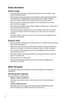
signal cables from the motherboard, ensure that all power cables are unplugged. • Seek professional assistance before using an adapter or encounter technical problems with the product, contact a qualified service technician or your retailer. About this guide This user guide contains the information - Asus P5G41-M SI VGA | User Manual - Page 7
of the following symbols used throughout this manual. DANGER/WARNING: Information to prevent injury to yourself when trying to complete a task. CAUTION: Information to prevent damage to the components when trying to complete a task. IMPORTANT: Instructions that you MUST follow to complete a task - Asus P5G41-M SI VGA | User Manual - Page 8
DIMM sockets support unbuffered non-ECC 800/667 MHz DDR2 memory modules - Supports up to 8GB system memory * Refer to www.asus.com for P5G41-M LX2: Realtek® RTL8103EL 10/100Mbps Ethernet PCIe controller VIA® VT1705 High Definition Audio 6-channel CODEC Supports Multi-streaming technology Supports - Asus P5G41-M SI VGA | User Manual - Page 9
2 8Mb Flash ROM, AMI BIOS, PnP, DMI 2.0, WfM 2.0, ACPI 2.0a, SM BIOS 2.5 2 x Serial ATA cables 1 x Ultra DMA 100/66 cable 1 x I/O shield 1 x Support DVD 1 x User Manual Drivers ASUS PC Probe II ASUS Update Anti-Virus software (OEM version) MicroATX form factor: 9.6 in x 7.5 in (24.4 cm x 19.1 cm - Asus P5G41-M SI VGA | User Manual - Page 10
that you must shut down the system and unplug the power cable before removing or plugging in any motherboard component. The illustration below shows the location of the onboard LED. SB_PWR P5G41-M LX2/GB ON OFF Standby Power Powered Off P5G41-M LX2/GB Onboard LED ASUS P5G41-M LX2 Series 1-1 - Asus P5G41-M SI VGA | User Manual - Page 11
pin module) Place this side towards the rear of the chassis. VGA CHA_FAN CPU_FAN USB34 USBPW1-4 LGA775 LAN1_USB12 RTL 8112L AUDIO ICS 9LPRS441 7 2 24.4cm(9.6in) EATXPWR Super I/O VIA VT1705 CD AAFP PCIEX16 P5G41-M LX2/GB PCI1 Intel® ICH7 SATA4 SATA3 SATA2 SATA1 8Mb BIOS PCI2 - Asus P5G41-M SI VGA | User Manual - Page 12
the PnP cap/socket contacts/motherboard components. ASUS will shoulder the cost of repair only if the PnP cap. The motherboard supports Intel® LGA775 processors with P5G41-M LX2/GB Channel Channel A Channel B Sockets DIMM_A1 DIMM_B1 P5G41-M LX2/GB 240-pin DDR2 DIMM sockets ASUS P5G41 - Asus P5G41-M SI VGA | User Manual - Page 13
OS when you want to install 4GB or more memory on the motherboard. • This motherboard does not support DIMMs made up of 256 megabits (Mb) chips or less. P5G41-M LX2 Series Motherboard Qualified Vendors Lists (QVL) DDR2-667MHz capability Vendor Part No. Size SS/ DS A-Data M2OAD5H3J4170I1C53 - Asus P5G41-M SI VGA | User Manual - Page 14
2.0~2.1V 1.9~2.1V 1.9-2.0V DIMM socket support (Optional) A* B* • • • • • • • • • • • • • • • • • • • • • • • • • • 1.8V • • 2.0V • • 1.8V • • 1.8V • • 1.8V • • - • • 2.0V • • 1.9-2.1V • • (continued on the next page) ASUS P5G41-M LX2 Series 1-5 - Asus P5G41-M SI VGA | User Manual - Page 15
/ DS: Double-sided DIMM support: • A*: Supports one module inserted into either slot as Single-channel memory configuration. • B*: Supports one pair of modules inserted into both slots as one pair of dual-channel memory configuration. Visit the ASUS website at www.asus.com for the latest QVL - Asus P5G41-M SI VGA | User Manual - Page 16
damage motherboard components. 1.5.1 supports PCI Express x1 network cards, SCSI cards, and other cards that comply with the PCI Express specifications. 1.5.5 PCI Express x16 slot This motherboard supports a PCI Express x16 graphics card that complies with the PCI Express specifications. ASUS P5G41 - Asus P5G41-M SI VGA | User Manual - Page 17
onboard button cell battery powers the RAM data in CMOS, which include system setup information such as system passwords. CLRTC 12 23 P5G41-M LX2/GB Normal (Default) Clear RTC P5G41-M LX2/GB Clear RTC RAM To erase the RTC RAM: 1. Turn OFF the computer and unplug the power cord. 2. Move the - Asus P5G41-M SI VGA | User Manual - Page 18
a corresponding setting in the BIOS. KBPWR 12 23 +5V +5VSB (Default) P5G41-M LX2/GB P5G41-M LX2/GB Keyboard Power Setting 3. USB device wake-up (3-pin USBPW1-4, USBPW5 (Default) USBPW5-8 P5G41-M LX2/GB 12 23 +5V +5VSB (Default) P5G41-M LX2/GB USB Device Wake Up ASUS P5G41-M LX2 Series 1-9 - Asus P5G41-M SI VGA | User Manual - Page 19
This port allows connection to a Local Area Network (LAN) through a network hub. Refer to the table below for the LAN port LED indications. P5G41-M LX2 LAN port LED indications LED (Orange) Status OFF ORANGE Description No link 100Mbps connection LED (Green) Status OFF GREEN Description No link - Asus P5G41-M SI VGA | User Manual - Page 20
available for connecting USB 2.0 devices. 8. Video Graphics Adapter (VGA) port. This 15-pin port is for a VGA monitor or other VGA-compatible devices. 9. COM port. This port at http://support.asus. com/PowerSupplyCalculator/PSCalculator.aspx?SLanguage=en-us for details. ASUS P5G41-M LX2 Series 1-11 - Asus P5G41-M SI VGA | User Manual - Page 21
forget to connect the fan cables to the fan connectors. Insufficient air flow inside the system may damage the motherboard components. These are not jumpers! Do not place jumper caps on the fan connectors! Only the 4-pin CPU fan supports the ASUS Q-Fan feature. P5G41-M LX2/GB CHA_FAN Rotation +12V - Asus P5G41-M SI VGA | User Manual - Page 22
on the Ultra DMA cable connector. This prevents incorrect insertion when you connect the IDE cable. • Use the 80-conductor IDE cable for Ultra DMA 100/66 IDE devices. If any device jumper is set as "Cable-Select," ensure that all other device jumpers have the same setting. ASUS P5G41-M LX2 Series - Asus P5G41-M SI VGA | User Manual - Page 23
with USB 2.0 specification that supports up to 480Mbps connection speed. USB+5V USB_P8USB_P8+ GND NC USB+5V USB_P6USB_P6+ GND NC P5G41-M LX2/GB USB56 PIN 1 USB78 PIN 1 USB+5V USB_P7USB_P7+ GND USB+5V USB_P5USB_P5+ GND P5G41-M LX2/GB USB2.0 connectors Never connect a 1394 cable to the USB - Asus P5G41-M SI VGA | User Manual - Page 24
front panel audio I/O module that supports either HD Audio or legacy AC`97 audio standard. Connect one end of the front panel audio I/O module cable to this connector. GND PRESENCE# GND GND Left Audio Channel P5G41-M LX2/GB P5G41-M LX2/GB Internal audio connector ASUS P5G41-M LX2 Series 1-15 - Asus P5G41-M SI VGA | User Manual - Page 25
pin F_PANEL) This connector supports several chassis-mounted functions. F_PANEL PLED PWRBTN PIN 1 P5G41-M LX2/GB +HDLED RESET P5G41-M LX2/GB System 2-pin connector is for the HDD Activity LED. Connect the HDD Activity LED cable to this connector. The HD LED lights up or flashes when data is read - Asus P5G41-M SI VGA | User Manual - Page 26
. Click an icon to display Support DVD/ motherboard information Click an item to install If Autorun is NOT enabled in your computer, browse the contents of the Support DVD to locate the file ASSETUP.EXE from the BIN folder. Double-click the ASSETUP.EXE to run the DVD. ASUS P5G41-M LX2 Series 1-17 - Asus P5G41-M SI VGA | User Manual - Page 27
DVD that comes with the motherboard package. Installing ASUS Update To install ASUS Update: 1. Place the support DVD in the optical drive. The Drivers menu appears. 2. Click the Utilities tab, then click ASUS Update. 3. Follow the onscreen instructions to complete the installation. Quit all Windows - Asus P5G41-M SI VGA | User Manual - Page 28
Follow the onscreen instructions to complete the updating process. 2.1.2 ASUS EZ Flash 2 The ASUS EZ Flash V3.44 FLASH TYPE: MXIC 25L8005 Current ROM BOARD: P5G41-M LX2/GB VER: 0211 (H:00 B:03) DATE: reboots the system when done. • This function supports USB flash disks with FAT 32/16 format and - Asus P5G41-M SI VGA | User Manual - Page 29
file from the ASUS website at www.asus.com. • The removable devices that ASUS CrashFree BIOS support vary with motherboard . The BIOS screens include navigation keys and brief online help to guide you in using the BIOS Setup program. Entering BIOS Setup at startup ASUS P5G41-M LX2 Series 2-3 - Asus P5G41-M SI VGA | User Manual - Page 30
setup screens shown in this section are for reference purposes only, and may not exactly match what you see on your screen. • Visit the ASUS website at www.asus.com to download the latest BIOS file for this motherboard. 2.3 Main menu When you enter the BIOS Setup program, the Main menu screen - Asus P5G41-M SI VGA | User Manual - Page 31
Mode Support On [S-ATA] Sets Serial ATA, Parallel ATA or both as native mode. Configuration options: [S-ATA+P-ATA] [S-ATA] [P-ATA]. IDE Detect Time Out (Sec) [35] Selects the time out value for detecting ATA/ATAPI devices. Configuration options: [0] [5] [10] [15] [20] [25] [30] [35] ASUS P5G41 - Asus P5G41-M SI VGA | User Manual - Page 32
2.3.5 System Information This menu gives you an overview of the general system specifications. The BIOS automatically detects the items in this menu. BIOS Information Displays the auto-detected BIOS information. Processor Displays the auto-detected CPU specification. System Memory Displays the auto- - Asus P5G41-M SI VGA | User Manual - Page 33
and set values may differ. • Key in ratio numbers directly. C1E Support [Enabled] Allows you to enable or disable C1E Support. Configuration options: [Disabled] [Enabled] Max CPUID Value Limit [Disabled] want to use the EIST. Configuration options: [Enabled] [Disabled] ASUS P5G41-M LX2 Series 2-7 - Asus P5G41-M SI VGA | User Manual - Page 34
Configuration options: [Enabled] [Disabled] Initiate Graphic Adapter [PEG/PCI] Allows you to select the graphics DIMMs into the DIMM sockets. Protect Audio Video Path Mode [Lite] This item is not HD Audio] Allows you to select the front panel support type. If High Definition Audio Front Panel used, - Asus P5G41-M SI VGA | User Manual - Page 35
the USB controller legacy mode is enabled. If no USB device is detected, the legacy USB support is disabled. Configuration options: [Disabled] [Enabled] [Auto] USB 2.0 Controller Mode [HiSpeed type. Configuration options: [Auto] [Floppy] [Forced FDD] [Hard Disk] [CDROM] ASUS P5G41-M LX2 Series 2-9 - Asus P5G41-M SI VGA | User Manual - Page 36
to display the configuration options. Main Advanced Power BIOS SETUP UTILITY Boot Tools Exit Suspend Mode [Auto] ACPI 2.0 Support [Enabled] ACPI APIC Support [Enabled] APM Configuration Hardware Monitor Select the ACPI state used for System Suspend. 2.5.1 Suspend Mode [Auto] Allows you - Asus P5G41-M SI VGA | User Manual - Page 37
voltage output through the onboard voltage regulators. CPU Q-Fan Function [Disabled] Allows you to enable or disable the CPU's Q-Fan function. Configuration options: [Disabled] [Enabled] ASUS P5G41-M LX2 Series 2-11 - Asus P5G41-M SI VGA | User Manual - Page 38
you to enable or disable the full screen logo display feature. Configuration options: [Disabled] [Enabled] Set this item to [Enabled] to use the ASUS MyLogo2™ feature. AddOn ROM Display Mode [Force BIOS] Sets the display mode for option ROM. Configuration options: [Force BIOS] [Keep Current] Bootup - Asus P5G41-M SI VGA | User Manual - Page 39
prompted. The message Password Installed appears after you set your password successfully. To change the user password, follow the same steps in setting a user password. ASUS P5G41-M LX2 Series 2-13 - Asus P5G41-M SI VGA | User Manual - Page 40
Tools Exit Press ENTER to run the utility to select and update BIOS. This utility supports 1.FAT 12/16/32 (r/w) 2.NTFS (read only) 3.CD-DISC (read only) 2.7.1 ASUS EZ Flash 2 Allows you to run ASUS EZ Flash 2. When you press , a confirmation message appears. Use the left/right arrow key
-
 1
1 -
 2
2 -
 3
3 -
 4
4 -
 5
5 -
 6
6 -
 7
7 -
8
-
9
-
10
-
11
-
12
-
13
-
14
-
15
-
16
-
17
-
18
-
19
-
20
-
21
-
22
-
23
-
24
-
25
-
26
-
27
-
28
-
29
-
30
-
31
-
32
-
33
-
34
-
35
-
36
-
37
-
38
-
39
-
40
 |
 |

Motherboard
P5G41-M LX2 Series
• P5G41-M LX2
• P5G41-M LX2/GB