Asus P5G41-M User Manual
Asus P5G41-M - LE/CSM Motherboard - Micro ATX Manual
 |
UPC - 610839172207
View all Asus P5G41-M manuals
Add to My Manuals
Save this manual to your list of manuals |
Asus P5G41-M manual content summary:
- Asus P5G41-M | User Manual - Page 1
P5G41-M Motherboard - Asus P5G41-M | User Manual - Page 2
Product warranty or service will not be extended if: (1) the product is repaired, modified or altered, unless such repair, modification of alteration is authorized in writing by ASUS; or (2) the serial number of the product is defaced or missing. ASUS PROVIDES THIS MANUAL "AS IS" WITHOUT WARRANTY - Asus P5G41-M | User Manual - Page 3
1-5 1.5.2 Screw holes 1-5 1.5.3 Motherboard layout 1-6 1.5.4 Layout contents 1-6 1.6 Central Processing Unit (CPU 1-7 1.6.1 Installing the CPU 1-7 1.6.2 Installing the CPU heatsink and fan 1-10 1.6.3 Uninstalling the CPU heatsink and fan 1-11 1.7 System memory 1-12 1.7.1 Overview 1-12 - Asus P5G41-M | User Manual - Page 4
system 1-32 1.11.2 Support DVD information 1-32 Chapter 2: BIOS information 2.1 Managing and updating your BIOS 2-1 2.1.1 ASUS Update utility 2-1 2.1.2 ASUS EZ Flash 2 utility 2-2 2.1.3 ASUS CrashFree BIOS 3 utility 2-3 2.2 BIOS setup program 2-4 2.2.1 BIOS menu screen 2-5 2.2.2 Menu - Asus P5G41-M | User Manual - Page 5
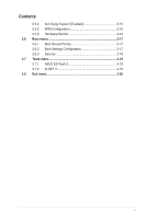
Contents 2.5.4 Anti Surgy Support [Enabled 2-15 2.5.5 APM Configuration 2-15 2.5.6 Hardware Monitor 2-16 2.6 Boot menu 2-17 2.6.1 Boot Device Priority 2-17 2.6.2 Boot Settings Configuration 2-17 2.6.3 Security 2-18 2.7 Tools menu 2-19 2.7.1 ASUS EZ Flash 2 2-19 2.7.2 AI NET 2 2-19 2.8 Exit - Asus P5G41-M | User Manual - Page 6
products at ASUS REACH website at http://green.asus.com/english used in accordance with manufacturer's instructions, may cause harmful interference to Changes or modifications to this unit not expressly approved by the party ICES-003. DO NOT throw the motherboard in municipal waste. This product has - Asus P5G41-M | User Manual - Page 7
motherboard service technician or your retailer. • The optical S/PDIF is an optional component (may or may not be included in your motherboard INSTRUCTIONS. Operation safety • Before installing the motherboard and adding devices on it, carefully read all the manuals wet. This motherboard should only be - Asus P5G41-M | User Manual - Page 8
need when installing and configuring the motherboard. How this guide is organized This guide contains the following parts: • Chapter 1: Product introduction This chapter describes the features of the motherboard and the new technology it supports. • Chapter 2: BIOS information This chapter tells how - Asus P5G41-M | User Manual - Page 9
unbuffered non-ECC 1066(overclocking) /800/667 MHz DDR2 memory modules - Supports up to 8GB system memory * Refer to www.asus.com or this user manual for the Memory QVL (Qualified Vendors Lists). ** When you install a total memory of 4GB capacity or more, Windows® 32-bit operating system - Asus P5G41-M | User Manual - Page 10
PnP, DMI v2.0, WfM 2.0, ACPI v2.0a, SM BIOS v2.5 Support DVD Contents Drivers ASUS PC Probe II ASUS LiveUpdate Utility Anti-virus software (OEM version) Accessories 2 x Serial ATA cables 1 x Ultra DMA 100/66 cable 1 x I/O shield User Manual Form factor MicroATX form factor: 9.6 in x 7.8 in (24 - Asus P5G41-M | User Manual - Page 11
with the list below. 1.2 Package contents Check your motherboard package for the following items. Motherboard Cables Accessories Application DVD Documentation ASUS P5G41-M motherboard 2 x Serial ATA cables 1 x Ultra DMA 100/66 cable 1 x I/O shield ASUS motherboard support DVD User Manual If - Asus P5G41-M | User Manual - Page 12
Memory Access technology the significantly optimized the use of available memory bandwith and reduces the latency of the memory other protected content. The interface of this motherboard supports dual VGA output both HDMI and RGB. Innovative ASUS features ASUS MyLogo2™ This feature allows you to - Asus P5G41-M | User Manual - Page 13
back up to 100 meters at 1 meter accuracy. ASUS EPU-L ASUS EPU (Engine Processing Unit) provides a total system power management. It detects reboot the system, and the BIOS automatically restores the CPU parameters to their default settings. Green ASUS This motherboard and its packaging comply with - Asus P5G41-M | User Manual - Page 14
reminder that you must shut down the system and unplug the power cable before removing or plugging in any motherboard component. The illustration below shows the location of the onboard LED. SB_PWR P5G41-M P5G41-M Onboard LED ON OFF Standy Power Powered Off 1-4 Chapter 1: Product introduction - Asus P5G41-M | User Manual - Page 15
chassis as indicated in the image below. 1.5.2 Screw holes Place six screws into the holes indicated by circles to secure the motherboard to the chassis. Do not overtighten the screws! Doing so can damage the motherboard. Place this side towards the rear of the chassis P5G41-M ASUS P5G41-M 1-5 - Asus P5G41-M | User Manual - Page 16
1.5.3 Motherboard layout 1 253 4 19.8cm(7.8in) 56 KBMS KBPWR CPU_FAN HDMI ATX12V DDR2 DIMM_A1 (64bit, 240-pin module) DDR2 DIMM_B1 (64bit, 240-pin module) PRI_IDE 24.4cm(9.6in) LGA775 7 VGA USB34 USBPW1-4 LAN1_USB12 Atheros L1E Intel® G41 SPDIF_O ICS 9LRS954 AUDIO 2 PCIEX1_1 - Asus P5G41-M | User Manual - Page 17
/motherboard components. ASUS will shoulder the cost motherboard supports Intel® LGA775 processors with the Intel® Enhanced Intel SpeedStep® Technology (EIST) and Hyper-Threading Technology. 1.6.1 Installing the CPU To install a CPU: 1. Locate the CPU socket on the motherboard. P5G41-M P5G41-M CPU - Asus P5G41-M | User Manual - Page 18
damage to the socket pins, do not remove the PnP cap unless you are installing a CPU. 3. Lift the load lever in the direction of the arrow to a 135º angle. tab A B Load lever PnP cap Load plate 4B 4A 3 5. Position the CPU over the socket, ensuring that the gold triangle is on the bottom‑left corner - Asus P5G41-M | User Manual - Page 19
6. Apply some Thermal Interface Material to the exposed area of the CPU that the heatsink will be in contact with, ensuring that it is spread in an even thin finger directly. 7. Close the load plate (A), then push the load lever (B) until it snaps into the A retention tab. B ASUS P5G41-M 1-9 - Asus P5G41-M | User Manual - Page 20
install the heatsink and fan assembly. Ensure that you have installed the motherboard to the chassis before you install the CPU fan and heatsink assembly. To install the CPU heatsink and fan: 1. Place the heatsink on top of the installed CPU, ensuring that the four fasteners match the holes on the - Asus P5G41-M | User Manual - Page 21
the CPU heatsink and fan: 1. Disconnect the CPU fan cable from the connector on the motherboard. 2. Rotate each fastener counterclockwise. 3. Pull up two fasteners at a time in a diagonal sequence to disengage the heatsink and fan assembly from the motherboard. A B A B B A B A ASUS P5G41 - Asus P5G41-M | User Manual - Page 22
reinstalling. 1.7 System memory 1.7.1 Overview The motherboard comes with two Double Data Rate 2 (DDR2) Dual Inline Memory Modules (DIMM) sockets. The figure illustrates the location of the DDR2 DIMM sockets: DIMM_A1 DIMM_B1 P5G41-M Channel Channel A Channel B P5G41-M 240-pin DDR2 DIMM sockets - Asus P5G41-M | User Manual - Page 23
to run at DDR2-667. If this happens, contact your memory vendor to check the ODT value. • Due to chipset limitation, DDR2-800 with CL=4 will be downgraded to run at DDR2-667 by default setting. If you want to operate with lower latency, adjust the memory timing manually. ASUS P5G41-M 1-13 - Asus P5G41-M | User Manual - Page 24
P5G41-M Motherboard Qualified Vendors Lists (QVL) DDR2-667 MHz capability Size 512MB 1GB 2GB 1GB 512MB 512MB 512MB 2GB 1GB 1GB 1GB AM4B5708MIJS7E0627B DS MID095D62864M8CEC DS Heat-Sink Package DS Heat-Sink Package DIMM support A* B G.SKILL F2-5400PHU2-2GBNT 5-5-5-15 G.SKILL DS D2 - Asus P5G41-M | User Manual - Page 25
DS SS DS DS SS SS DS DS DS DS Chip No. DIMM support A* B* DDRII6408-6E • DDRII1208-6E 8115 • • HY5PS12821AFP-Y5 • -3 • U2S12D30YP-6E • • U2S24D30TP-6E • • DDR2 800 Qualified Vendors List Size Vendor 2GB (2 x 1GB) 512MB DDR2 800 4GB (2 x 2GB) 1GB 512MB 2GB 2GB ASUS P5G41-M 1-15 - Asus P5G41-M | User Manual - Page 26
DDR2 800 Qualified Vendors List Size 1GB (2 x 512MB) 1GB 1GB 1GB 1GB 2GB 4GB 1GB G.SKILL F2-6400CL5D-1GBNQ CL Chip Brand SS/DS Chip No. 5-5-5-15 G.SKILL SS Heat-Sink Package DIMM support A* B* •• G.SKILL F2-6400CL4D-2GBHK 4 G.SKILL F2-6400CL4D-2GBPK 4 G.SKILL F2-6400CL4D-4GBPK 4 G. - Asus P5G41-M | User Manual - Page 27
DDR2 800 Qualified Vendors List Size 2GB 4GB 1GB 2GB 1GB 1GB 1GB 1GB 2GB 2GB 2GB 512MB 1GB 1GB 512MB 2GB 1GB 4GB 1GB -2.50726E MS18T 51280-2.5P0710 MS18T 51280-2.5P0716 U2S12D30TP-8E U2S24D30TP-8E Heat-Sink Package (continued on the next page) DIMM support A* B •• ASUS P5G41-M 1-17 - Asus P5G41-M | User Manual - Page 28
No. N/A DS Heat-Sink Package DIMM support A* B* •• N/A DS Heat-Sink Package •• N/A DS Heat-Sink Package •• N/A DS Qimonda DS Transcend DS Heat-Sink Package •• 800HY818T1G800C2F-2.5 • • TQ123YBF8 T0747 •• DDR2 1066 Qualified Vendors List Size Vendor Part No. CL Chip Brand - Asus P5G41-M | User Manual - Page 29
A*: Supports one module inserted into either slot as the single-channel memory configuration. • B*: Supports one pair of modules inserted into both the blue slots as one pair of dual-channel memory configuration. Visit the ASUS website at www.asus.com for the latest QVL. ASUS P5G41-M 1-19 - Asus P5G41-M | User Manual - Page 30
severe damage to both the motherboard and the components. To install a DIMM: 1. Press the retaining clips outward to unlock a DDR2 DIMM socket. 2. Align press the retaining clips outward to unlock the DIMM. 2 Support the DIMM lightly with your fingers when pressing the retaining clips - Asus P5G41-M | User Manual - Page 31
x1 slot This motherboard supports PCI Express x1 network cards, SCSI cards, and other cards that comply with the PCI Express specifications. 1.8.5 PCI Express x16 slot This motherboard supports a PCI Express x16 graphics card that complies with the PCI Express specifications. ASUS P5G41-M 1-21 - Asus P5G41-M | User Manual - Page 32
RTC) RAM in CMOS. You can clear the CMOS memory of date, time, and system setup parameters by erasing such as system passwords. CLRTC 12 23 P5G41-M Normal (Default) P5G41-M Clear RTC RAM Clear RTC To erase CPU Parameter Recall (C.P.R.) feature. Shut down and reboot the system, then the BIOS - Asus P5G41-M | User Manual - Page 33
corresponding setting in the BIOS. KBPWR 12 23 +5V +5VSB (Default) P5G41-M P5G41-M Keyboard Power Setting CPU, DRAM in slow refresh, power supply in reduced power mode). USBPW1-4 12 23 +5V +5VSB (Default) USBPW5-8 P5G41-M 12 23 +5V +5VSB (Default) P5G41-M USB Device Wake Up ASUS P5G41 - Asus P5G41-M | User Manual - Page 34
Connectors 1.10.1 Rear panel connectors 1 2 3 45 11 10 9 8 76 1. PS/2 mouse port (green). This port is for a PS/2 mouse. 2. Video Graphics Adapter (VGA) port. This 15-pin port is for a VGA monitor or other VGA-compatible devices. 3. LAN (RJ-45) port. This port allows Gigabit connection to - Asus P5G41-M | User Manual - Page 35
SATA3 P5G41-M SATA connectors 2. Speaker connector (4-pin SPEAKER) This 4-pin connector is for the chassis-mounted system warning speaker. The speaker allows you to hear system beeps and warnings. SPEAKER +5V GND GND Speaker Out P5G41-M PIN 1 P5G41-M Speaker Out Connector ASUS P5G41-M 1-25 - Asus P5G41-M | User Manual - Page 36
: blue, black, and gray. Connect the blue connector to the motherboard's IDE connector, then select one of the following modes to configure conductor IDE cable for Ultra DMA 100/66/33 IDE devices. PRI_IDE PIN1 P5G41-M P5G41-M IDE connector NOTE:Orient the red markings on the IDE ribbon cable to - Asus P5G41-M | User Manual - Page 37
GND GND PSON# GND -12 Volts +3 Volts • For a fully configured system, we recommend that you use a power supply unit (PSU) that complies with ATX 12 V Specification 2.0 (or later version) and provides a minimum power of 400 W. • or may not boot up if the power is inadequate. ASUS P5G41-M 1-27 - Asus P5G41-M | User Manual - Page 38
max.) at +12V. Connect the fan cables to the fan connectors on the motherboard, ensuring that the black wire of each cable matches the ground pin of the connector. CPU_FAN GND CPU FAN PWR CPU FAN IN CPU FAN PWM P5G41-M P5G41-M fan connectors CHA_FAN Rotation +12V GND Do not forget to connect the - Asus P5G41-M | User Manual - Page 39
supports up to 480 Mbps connection speed. USB+5V USB_P8USB_P8+ GND NC USB+5V USB_P6USB_P6+ GND NC P5G41-M USB56 PIN 1 USB78 PIN 1 USB+5V USB_P7USB_P7+ GND USB+5V USB_P5USB_P5+ GND P5G41-M USB2.0 connectors Never connect a 1394 cable to the USB connectors. Doing so will damage the motherboard - Asus P5G41-M | User Manual - Page 40
) This connector supports several chassis-mounted functions. PWR LED PWR BTN HD_LED RESET F_PANEL P5G41-M GND PWR PLEDPLED+ P5G41-M System panel on or puts the system in sleep or soft-off mode depending on the BIOS settings. Pressing the power switch for more than four seconds while the system - Asus P5G41-M | User Manual - Page 41
BUSY ACK# PD7 PD6 PD5 PD4 PD3 PD2 PD1 PD0 STB# P5G41-M PIN 1 GND GND GND GND GND GND GND GND SLIN# INIT# ERR# AFD P5G41-M Parallel Port Connector 11. Serial port connector (10-1 pin COM) the back of the system chassis. COM1 PIN 1 P5G41-M P5G41-M Serial port (COM1) connector ASUS P5G41-M 1-31 - Asus P5G41-M | User Manual - Page 42
to avail all motherboard features. The contents of the Support DVD are subject to change at any time without notice. Visit the ASUS website at www.asus.com for updates. To run the Support DVD Place the Support DVD to the optical drive. The DVD automatically displays the Drivers menu if Autorun - Asus P5G41-M | User Manual - Page 43
is available in the support DVD that comes with the motherboard package. Installing ASUS Update To install ASUS Update: 1. Place the support DVD in the optical drive. The Drivers menu appears. 2. Click the Utilities tab, then click ASUS Update. 3. Follow the onscreen instructions to complete the - Asus P5G41-M | User Manual - Page 44
Updating from a BIOS file a. Select Update BIOS from a file, then click Next. b. Locate the BIOS file from the Open window, then click Open. 3. Follow the onscreen instructions to complete the updating process. 2.1.2 ASUS EZ Flash 2 utility The ASUS EZ Flash 2 feature allows you to update the BIOS - Asus P5G41-M | User Manual - Page 45
system boot failure! 2.1.3 ASUS CrashFree BIOS 3 utility The ASUS CrashFree BIOS 3 is an auto recovery tool that allows you to restore the BIOS file when it fails or gets corrupted during the updating process. You can update a corrupted BIOS file using the motherboard support DVD or a USB flash - Asus P5G41-M | User Manual - Page 46
or reset the system while updating the BIOS! Doing so can cause system boot failure! The recovered BIOS may not be the latest BIOS version for this motherboard. Download the latest BIOS file from the ASUS website at www.asus.com. 2.2 BIOS setup program This motherboard supports a programmable Serial - Asus P5G41-M | User Manual - Page 47
screen. • Visit the ASUS website at www.asus.com to download the latest BIOS file for this motherboard. 2.2.1 BIOS menu screen Menu items Menu bar Main Advanced Power Configuration fields BIOS SETUP UTILITY Boot Tools key on the keyboard until the desired item is highlighted. ASUS P5G41-M 2-5 - Asus P5G41-M | User Manual - Page 48
change the value of a field, select it then press to display a list of options. Refer to 2.2.7 Pop-up window. 2.2.7 Pop-up window Select a screen. Main Advanced BIOS SETUP UTILITY Power Boot Tools Exit Suspend Mode ACPI Version Features ACPI APIC support APM Configuration Hardware - Asus P5G41-M | User Manual - Page 49
you to set the system date. 2.3.3 Primary IDE Master/Slave, SATA1~4 While entering Setup, the BIOS automatically detects the presence of IDE/SATA devices. There is a separate submenu for each IDE/SATA device ARMD] This item does not appear when you select the SATA 1/2/3/4 devices. ASUS P5G41-M 2-7 - Asus P5G41-M | User Manual - Page 50
the data transfer from and to the device occurs multiple sectors at a time if the device supports multi-sector transfer feature. When set to [Disabled], the data transfer from and to the device devices. Configuration options: [0] [5] [10] [15] [20] [25] [30] [35] 2-8 Chapter 2: BIOS information - Asus P5G41-M | User Manual - Page 51
the general system specifications. The BIOS automatically detects the items in this menu. BIOS Information Displays the auto-detected BIOS information. Processor Displays the auto-detected CPU specification. System Memory Displays the auto-detected system memory. 2.4 Advanced menu The Advanced menu - Asus P5G41-M | User Manual - Page 52
MANUAL]. CPU Frequency [xxx] Displays the frequency sent by the clock generator to the system bus and PCI bus. The value of this item is auto-detected by the BIOS. Use the and keys to adjust the CPU [Auto] Allows you to set the DDR2 operating frequency. Configuration options: [Auto] - Asus P5G41-M | User Manual - Page 53
CPU-related information that the BIOS automatically detects. Ratio CMOS Setting [Auto] Sets the ratio between CPU core clock and the FSB frequency. Configuration option: [Auto] • If an invalid ratio is set in CMOS then actual and set values may differ. • Key in ratio numbers directly. C1E Support - Asus P5G41-M | User Manual - Page 54
an Intel® CPU that supports the Enhanced Intel memory. Configuration options: [128MB] [256MB] [Maximum DVMT] The [Maximum DVMT] option only appears when installing 1GB DDR2 DIMMs into the DIMM sockets. Protect Audio Video Path Mode [Lite] This item is not user- configurable. 2-12 Chapter 2: BIOS - Asus P5G41-M | User Manual - Page 55
options: [Enabled] [Disabled] Front Panel Type [HD Audio] Allows you to select the front panel support type. If High Definition Audio Front Panel used, set this item to [HD Audio] mode. Configuration disable or enable the USB functions. Configuration options: [Disabled] [Enabled] ASUS P5G41-M 2-13 - Asus P5G41-M | User Manual - Page 56
no USB device is detected, the legacy USB support is disabled. Configuration options: [Disabled] [Enabled PnP or legacy ISA devices, and setting the memory size block for legacy ISA devices. Take Plug and Play O/S [No] When set to [No], BIOS configures all the devices in the system. When set to - Asus P5G41-M | User Manual - Page 57
Advanced Power BIOS SETUP UTILITY Boot Tools Exit Suspend Mode ACPI 2.0 Support ACPI APIC Support Anti Surgy Support [Auto] is included in the RSDT pointer list. Configuration options: [Disabled] [Enabled] 2.5.4 Anti Surgy Support [Enabled] Allows you to [Last State] ASUS P5G41-M 2-15 - Asus P5G41-M | User Manual - Page 58
monitor automatically detects and displays the motherboard and CPU temperatures. Select Ignored if you do not wish to display the detected temperatures. CPU Fan Speed [xxxxRPM] or [ automatically detects the voltage output through the onboard voltage regulators. 2-16 Chapter 2: BIOS information - Asus P5G41-M | User Manual - Page 59
item to [Enabled] to use the ASUS MyLogo2™ feature. AddOn ROM Display Mode [Force BIOS] Sets the display mode for option ROM. Configuration options: [Force BIOS] [Keep Current] Bootup Num-Lock [On Press DEL to run Setup during POST. Configuration options: [Disabled] [Enabled] ASUS P5G41-M 2-17 - Asus P5G41-M | User Manual - Page 60
twice. The message Password uninstalled appears. If you forget your BIOS password, you can clear it by erasing the CMOS Real Time Clock ( . 2. On the password box, key in a password containing up to six letters or numbers, or both. 3. Confirm the password when prompted. The message - Asus P5G41-M | User Manual - Page 61
to run the utility to select and update BIOS. This utility supports 1.FAT 12/16/32 (r/w) 2.NTFS (read only) 3.CD-DISC (read only) 2.7.1 ASUS EZ Flash 2 Allows you to run ASUS EZ Flash 2. When you press - Asus P5G41-M | User Manual - Page 62
the changes that you made to the Setup program. If you made changes to fields other than System Date, System Time, and Password, the BIOS asks for a confirmation before exiting. Discard Changes This option allows you to discard the selections you made and restore the previously saved values. After
-
 1
1 -
 2
2 -
 3
3 -
 4
4 -
 5
5 -
 6
6 -
 7
7 -
8
-
9
-
10
-
11
-
12
-
13
-
14
-
15
-
16
-
17
-
18
-
19
-
20
-
21
-
22
-
23
-
24
-
25
-
26
-
27
-
28
-
29
-
30
-
31
-
32
-
33
-
34
-
35
-
36
-
37
-
38
-
39
-
40
-
41
-
42
-
43
-
44
-
45
-
46
-
47
-
48
-
49
-
50
-
51
-
52
-
53
-
54
-
55
-
56
-
57
-
58
-
59
-
60
-
61
-
62
 |
 |

Motherboard
P5G41-M