Asus P5G41C-M User Manual
Asus P5G41C-M Manual
 |
View all Asus P5G41C-M manuals
Add to My Manuals
Save this manual to your list of manuals |
Asus P5G41C-M manual content summary:
- Asus P5G41C-M | User Manual - Page 1
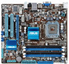
P5G41C-M Motherboard - Asus P5G41C-M | User Manual - Page 2
including the GPL Software and/or LGPL Software, which will be no earlier than December 1, 2011, either (1) for free by downloading it from http://support.asus.com/download; or (2) for the cost of reproduction and shipment, which is dependent on the preferred carrier and the location where you want - Asus P5G41C-M | User Manual - Page 3
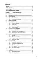
About this guide vii P5G41C-M specifications summary ix Chapter 1: Product introduction 1.1 Welcome 1-1 1.2 Package contents 1-1 1.3 Special features 1-1 1.3.1 Product highlights 1-1 1.3.2 Innovative ASUS features 1-2 1.4 Before you proceed 1-4 1.5 Motherboard overview 1-5 1.5.1 Placement - Asus P5G41C-M | User Manual - Page 4
an operating system 1-30 1.11.2 Support DVD information 1-30 Chapter 2: BIOS information 2.1 Managing and updating your BIOS 2-1 2.1.1 ASUS Update utility 2-1 2.1.2 ASUS EZ Flash 2 2-2 2.1.3 ASUS CrashFree BIOS 2-3 2.2 BIOS setup program 2-4 2.2.1 BIOS menu screen 2-5 2.2.2 Menu bar - Asus P5G41C-M | User Manual - Page 5
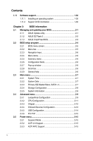
Contents 2.5.4 Anti Surge Support 2-15 2.5.5 APM Configuration 2-16 2.5.6 Hardware Monitor 2-16 2.6 Boot menu 2-17 2.6.1 Boot Device Priority 2-17 2.6.2 Boot Settings Configuration 2-17 2.6.3 Security 2-18 2.7 Tools menu 2-20 2.7.1 ASUS EZ Flash 2 2-20 2.7.2 Express Gate 2-20 2.7.3 AI NET - Asus P5G41C-M | User Manual - Page 6
accordance with manufacturer's instructions, may cause harmful to an outlet on a circuit different from that to which the receiver is of the monitor to the graphics card is required to assure compliance ASUS REACH website at http://green.asus.com/english/REACH.htm. DO NOT throw the motherboard - Asus P5G41C-M | User Manual - Page 7
. • If you encounter technical problems with the product, contact a qualified service technician or your retailer. About this guide This user guide contains the information you need when installing and configuring the motherboard. How this guide is organized This guide contains the following parts - Asus P5G41C-M | User Manual - Page 8
IMPORTANT: Instructions that you MUST follow to complete a task. NOTE: Tips and additional information to help you complete a task. Where to find more information Refer to the following sources for additional information and for product and software updates. 1. ASUS websites The ASUS website - Asus P5G41C-M | User Manual - Page 9
® Technology (EIST) * Refer to www.asus.com for Intel® CPU support list. Northbridge: Intel® G41 Southbridge: Intel® ICH7 1333/1066/800 MHz Dual channel memory architecture - 2 x 240-pin DIMM sockets support unbuffered non-ECC 1333(O.C.)/1066/800 MHz DDR3 memory modules - 2 x 240-pin DIMM sockets - Asus P5G41C-M | User Manual - Page 10
x 24-pin EATX power connector 1 x 4-pin ATX 12V power connector 8Mb Flash ROM, AMI BIOS, PnP, DMI 2.0, WfM 2.0, ACPI 2.0a, SM BIOS 2.5 WOL, PXE, WOR by Ring, PME Wake up 1 x Ultra DMA 100/66/33 cable 2 x Serial ATA cables 1 x I/O shield 1 x User Manual Drivers ASUS PC Probe II ASUS Update Anti-Virus - Asus P5G41C-M | User Manual - Page 11
the list below. 1.2 Package contents Check your motherboard package for the following items. Motherboard Cables Accessories Application DVD Documentation ASUS P5G41C-M motherboard 2 x Serial ATA cables 1 x Ultra DMA 100/66/33 cable 1 x I/O shield ASUS motherboard support DVD User Manual If - Asus P5G41C-M | User Manual - Page 12
and reduces the latency of the memory accesses. Dual channel DDR3 1333(O.C.) / DDR2 1066(O.C.) support This motherboard supports DDR3 1333(O.C.)/1066/800MHz and DDR2 1066(O.C.)/800/667MHz memory providing great performance for 3D graphics and other memory-demanding applications. Serial ATA 3Gb - Asus P5G41C-M | User Manual - Page 13
the system hangs due to overclocking failure. C.P.R. eliminates the need to open the system chassis and clear the RTC data. Simply shut down and reboot the system, and the BIOS automatically restores the CPU parameters to their default settings. Green ASUS This motherboard and its packaging comply - Asus P5G41C-M | User Manual - Page 14
1.4 Before you proceed Take note of the following precautions before you install motherboard components or change any motherboard settings. • Unplug the power cord from the wall socket before touching any component. • Before handling components, use a grounded wrist strap or touch a safely grounded - Asus P5G41C-M | User Manual - Page 15
of the chassis as indicated in the image below. 1.5.2 Screw holes Place six screws into the holes indicated by circles to secure the motherboard to the chassis. Do not overtighten the screws! Doing so can damage the motherboard. Place this side towards the rear of the chassis ASUS P5G41C-M 1-5 - Asus P5G41C-M | User Manual - Page 16
Motherboard layout 1.5.4 Layout contents Connectors/Jumpers/Slots/LED 1. ATX power connectors (24-pin EATXPWR, 4-pin ATX12V) 2. CPU and chassis fan connectors (4-pin CPU_FAN, 3-pin CHA_FAN) 3. Intel LGA775 CPU socket 4. DDR2 and DDR3 DIMM slots 5. IDE connector (40-1 pin PRI_IDE) 6. Clear RTC RAM - Asus P5G41C-M | User Manual - Page 17
Intel® Enhanced Intel SpeedStep® Technology (EIST) and Hyper-Threading Technology. 1.6.1 Installing the CPU To install a CPU: 1. Locate the CPU socket on the motherboard. Before installing the CPU, ensure that the cam box is facing towards you and the load lever is on your left. ASUS P5G41C-M 1-7 - Asus P5G41C-M | User Manual - Page 18
to the socket pins, do not remove the PnP cap unless you are installing a CPU. 3. Lift the load lever in the direction of the arrow to a 135º cap from the load plate window to remove (4B). Retention tab A B Load lever PnP cap Load plate 4B 4A 3 5. Position the CPU over the socket, ensuring that - Asus P5G41C-M | User Manual - Page 19
6. Apply some Thermal Interface Material to the exposed area of the CPU that the heatsink will be in contact with, ensuring that it is spread in an even thin finger directly. 7. Close the load plate (A), then push the load lever (B) until it snaps into the A retention tab. B ASUS P5G41C-M 1-9 - Asus P5G41C-M | User Manual - Page 20
CPU, ensuring that the four fasteners match the holes on the motherboard. Orient the heatsink and fan assembly such that the CPU fan cable is closest to the CPU A B B A 1 1 B A The type of CPU heatsink and fan assembly may differ, but the installation steps and functions should remain the same. - Asus P5G41C-M | User Manual - Page 21
CPU heatsink and fan: 1. Disconnect the CPU fan cable from the connector on the motherboard. 2. Rotate each fastener counterclockwise. 3. Pull up two fasteners at a time in a diagonal sequence to disengage the heatsink and fan assembly from the motherboard. A A B B B A B A ASUS P5G41C - Asus P5G41C-M | User Manual - Page 22
. 5. Rotate each fastener clockwise to ensure correct orientation when reinstalling. 1.7 System memory 1.7.1 Overview The motherboard comes with two Double Data Rate 2 (DDR2) and two Double Data Rate 3 (DDR3) Dual Inline Memory Modules (DIMM) sockets. The figure illustrates the location of the DIMM - Asus P5G41C-M | User Manual - Page 23
than the vendor-marked value. • For system stability, use a more efficient cooling system to support a full memory load (2 DIMMs) or overclocking conditions. P5G41C-M Motherboard Qualified Vendors Lists (QVL) DDR3-1066 MHz capability Vendor Part No. Size SS/ DS Chip Brand Chip NO. Timing - Asus P5G41C-M | User Manual - Page 24
DDR3-1333 CL9-9-9-24 1024MB SS GV34GB1333C7DC 2048MB DS GEIL GG34GB1333C9DC 4096MB(Kit of 2) DS GEIL DDR3 - - 9-9-9-24 9FF22D9KPT 9 - 6-6-6-20 9KF27D9KPT 9 - 6-6-6-20 - 6-6-6-20 Voltage DIMM socket support (Optional) A* B* - • • 1.65-1.85V • • - • • 1.65-1.85V • - Asus P5G41C-M | User Manual - Page 25
DDR3-1333 9-9-9 PC3-10600 DDR3-1333 9-9-9 M2Y2G64CB8HA9N-CG M2Y2G64CB8HC9N-CG Kingtiger 2GB DIMM PC3-10666 Kingtiger PATRIOT PATRIOT PATRIOT PATRIOT SILICON POWER SILICON POWER SILICON POWER 65V 1.60V - - - - - - - - DIMM socket support (Optional) A* B* • • • • • • • • ASUS P5G41C-M 1-15 - Asus P5G41C-M | User Manual - Page 26
DDR2-667 MHz capability Vendor Part No. Size SS/ DS Chip Brand Chip NO. Timing DIMM socket Voltage support (Optional) A* B* A-Data M2OAD5H3J4170I1C53 2048MB DS A-Data AD20908A8A-3EG 30724 - - • • G.SKILL F2-5400PHU2-2GBNT 2048MB(Kit of 2) DS G.SKILL D2 64M8CCF 0815 C7173S 5-5-5-15 - Asus P5G41C-M | User Manual - Page 27
2048MB DS Chip Brand Chip NO. GEIL - Timing 5 Voltage - DIMM socket support (Optional) A* B* • • GEIL - 5 1.8V • • GEIL - -E 5 - • • V-Data VD29608A8A-25EG20813 - - • • Samsung K4T51083QE - - • • Hynix H5PS1G83EFRS6C 852AK - - • • ASUS P5G41C-M 1-17 - Asus P5G41C-M | User Manual - Page 28
module inserted into any slot as single-channel memory configuration. • B*: Supports one pair of modules inserted into either the black slots or the blue slots as one pair of dual-channel memory configuration. Visit the ASUS website at www.asus.com for the latest QVL. 1-18 Chapter 1: Product - Asus P5G41C-M | User Manual - Page 29
the power supply before adding or removing DIMMs or other system components. Failure to do so can cause severe damage to both the motherboard and the Simultaneously press the retaining clips outward to unlock the DIMM. 2 Support the DIMM lightly with your fingers when pressing the retaining clips - Asus P5G41C-M | User Manual - Page 30
PCI specifications. 1.8.4 PCI Express x1 slot This motherboard supports PCI Express x1 network cards, SCSI cards, and other cards that comply with the PCI Express specifications. 1.8.5 PCI Express x16 slot This motherboard supports a PCI Express x16 graphics card that complies with the PCI Express - Asus P5G41C-M | User Manual - Page 31
battery. • You do not need to clear the RTC when the system hangs due to overclocking. For system failure due to overclocking, use the CPU Parameter Recall (C.P.R.) feature. Shut down and reboot the system, then the BIOS automatically resets parameter settings to default values. ASUS P5G41C-M 1-21 - Asus P5G41C-M | User Manual - Page 32
ORANGE GREEN Description 10 Mbps connection 100 Mbps connection 1 Gbps connection ACT/LINK SPEED LED LED LAN port 3. Line In port (light blue). This port connects to the tape, CD, DVD audio module in the front panel to support an 8-channel audio output. 1-22 Chapter 1: Product introduction - Asus P5G41C-M | User Manual - Page 33
is for a VGA monitor or other VGA-compatible devices. 10. HDMI port. This port front panel audio I/O module that supports either HD Audio or legacy AC`97 connector to avail of the motherboard's high-definition audio capability. the Front Panel Type item in the BIOS setup to [HD Audio]. If you - Asus P5G41C-M | User Manual - Page 34
the fan connectors. Insufficient air flow inside the system may damage the motherboard components. These are not jumpers! Do not place jumper caps on the fan connectors! Only the 4-pin CPU fan supports the ASUS Q-FAN feature. 3. Digital audio connector (4-1 pin SPDIF_OUT) This connector is for an - Asus P5G41C-M | User Manual - Page 35
not boot up if the power is inadequate. • If you are uncertain about the minimum power supply requirement for your system, refer to the Recommended Power Supply Wattage Calculator at http://support.asus. com/PowerSupplyCalculator/PSCalculator.aspx?SLanguage=en-us for details. ASUS P5G41C-M 1-25 - Asus P5G41C-M | User Manual - Page 36
disk drives. The Serial ATA 3Gb/s is backward compatible with Serial ATA 1.5Gb/s specification. The data transfer rate of the Serial ATA 3Gb/s is faster than the standard parallel ATA with 133 MB/s (Ultra DMA133). Install the Windows® XP Service Pack 2 or later version before using Serial ATA - Asus P5G41C-M | User Manual - Page 37
DMA 100/66/33 signal cable: blue, black, and gray. Connect the blue connector to the motherboard's IDE connector, then select one of the following modes to configure your device. Single device Two devices -Select," ensure that all other device jumpers have the same setting. ASUS P5G41C-M 1-27 - Asus P5G41C-M | User Manual - Page 38
8. System panel connector (20-8 pin PANEL) This connector supports several chassis-mounted functions. • System power LED (2-pin PLED) This 2-pin connector is for the system power LED. Connect the chassis power LED cable to this connector. The system power LED lights up when you turn on the system - Asus P5G41C-M | User Manual - Page 39
connectors comply with USB 2.0 specification that supports up to 480 Mbps connection speed. Never connect a 1394 cable to the USB connectors. Doing so will damage the motherboard! The USB module cable is purchased system chassis. The serial port module is purchased separately. ASUS P5G41C-M 1-29 - Asus P5G41C-M | User Manual - Page 40
you install Windows® XP Service Pack 3 or later version / Windows® Vista Service Pack 1 or later version before installing the drivers for better compatibility and system stability. 1.11.2 Support DVD information The Support DVD that comes with the motherboard package contains the drivers, software - Asus P5G41C-M | User Manual - Page 41
motherboard BIOS using the ASUS Update utility. 2.1.1 ASUS Update utility The ASUS Update is a utility that allows you to manage, save, and update the motherboard BIOS in Windows® environment. • ASUS Update requires an Internet connection either through a network or an Internet Service Provider - Asus P5G41C-M | User Manual - Page 42
from the Open window, then click Open. 3. Follow the onscreen instructions to complete the updating process. 2.1.2 ASUS EZ Flash 2 The ASUS EZ Flash 2 feature allows you to update the BIOS without using an OS‑based utility. Before you start using this utility, download the latest BIOS file from the - Asus P5G41C-M | User Manual - Page 43
the motherboard support DVD or a removable device that contains the updated BIOS file. • Before using this utility, rename the BIOS file in the removable device into P5G41CM.ROM. • The BIOS file in the support DVD may not be the latest version. Download the latest BIOS file from the ASUS website - Asus P5G41C-M | User Manual - Page 44
Menu. See section 2.8 Exit Menu. • The BIOS setup screens shown in this section are for reference purposes only, and may not exactly match what you see on your screen. • Visit the ASUS website at www.asus.com to download the latest BIOS file for this motherboard. 2-4 Chapter 2: BIOS information - Asus P5G41C-M | User Manual - Page 45
menu screen Menu items Menu bar Main Advanced Power Configuration fields BIOS SETUP UTILITY Boot Tools Exit General help System Time [00:31:48] System Date [Tue 01/08/2002] Use bar, press the right or left arrow key on the keyboard until the desired item is highlighted. ASUS P5G41C-M 2-5 - Asus P5G41C-M | User Manual - Page 46
settings. Some of the navigation keys differ from one screen to another. list of options. Refer to 2.2.7 Pop-up window. 2.2.7 Pop-up window Select a menu item then press to display a pop-up window BIOS SETUP UTILITY Power Boot Tools Exit Suspend Mode ACPI 2.0 Support ACPI APIC support - Asus P5G41C-M | User Manual - Page 47
for information on the menu screen items and how to navigate through them. Main Advanced BIOS SETUP UTILITY Power Boot Tools Exit System Time System Date Primary IDE Master Primary IDE Slave SATA 1 ] [ARMD] This item does not appear when you select the SATA 1/2/3/4 devices. ASUS P5G41C-M 2-7 - Asus P5G41C-M | User Manual - Page 48
to configure the item. ATA/IDE Configuration [Enhanced] Allows you to set the ATA/IDE configuration. Configuration options: [Disabled] [Compatible] [Enhanced] Enhanced Mode Support On [S-ATA] Sets Serial ATA, Parallel ATA or both as native mode. Configuration options: [S-ATA+P-ATA] [S-ATA] [P-ATA - Asus P5G41C-M | User Manual - Page 49
either one of the preset overclocking configuration options: Manual - allows you to individually set overclocking parameters. Auto - loads the optimal settings for the system. Overclock Profile - loads overclocking profiles with optimal parameters for stability when overclocking. ASUS P5G41C-M 2-9 - Asus P5G41C-M | User Manual - Page 50
Overclocking item to [MANUAL]. CPU Frequency [xxx] Displays the frequency sent by the clock generator to the system bus and PCI bus. The value of this item is auto-detected by the BIOS. Use the and keys to adjust the CPU v v v 800MHz v v v DDR3 DRAM Frequency 960MHz 1000MHz 1067MHz v v - Asus P5G41C-M | User Manual - Page 51
CPU-related information that the BIOS automatically detects. Ratio CMOS Setting [Auto] Sets the ration between CPU core clock and the FSB frequency. Configuration option: [Auto] • If an invalid ratio is set in CMOS then actual and set values may differ. • Key in ratio numbers directly. C1E Support - Asus P5G41C-M | User Manual - Page 52
when you installed an Intel® Pentium® 4 or later CPU that supports the Enhanced Intel SpeedStep® Technology (EIST). Intel(R) SpeedStep( ] [PEG/PCI] IGD Graphics Mode Select [Enabled, 32MB] Allows you to select the amout of system memory used by the Interanal graphics device. Configuration options: [ - Asus P5G41C-M | User Manual - Page 53
Graphics Memory Size [No VT mode, 2MB] This item is not user- configurable. DVMT Memory [256MB] Allows you to select the DVMT memory you to select the front panel support type. If High Definition Audio Front onboard LAN controller. This item appears only when the Onboard LAN item ASUS P5G41C-M 2-13 - Asus P5G41C-M | User Manual - Page 54
mode is enabled. If no USB device is detected, the legacy USB support is disabled. Configuration options: [Disabled] [Enabled] [Auto] USB 2.0 Reset Delay [20 Sec] Allows you to set the maximum time that the BIOS waits for the USB storage device to initialize. Configuration options: [10 Sec] [20 - Asus P5G41C-M | User Manual - Page 55
, and setting the memory size block for legacy No] When set to [No], BIOS configures all the devices in the Power BIOS SETUP UTILITY Boot Tools Exit Suspend Mode ACPI 2.0 Support ACPI APIC Support Anti Surge Support list. Configuration options: [Disabled] [Enabled] 2.5.4 Anti Surge Support - Asus P5G41C-M | User Manual - Page 56
power supply that provides at least 1A on the +5VSB lead. Configuration options: [Disabled] [Enabled] 2.5.6 Hardware Monitor CPU Temperature [xxxºC/xxxºF] or [Ignored] MB Temperature [xxxºC/xxxºF] or [Ignored] The onboard hardware monitor automatically detects and displays the motherboard and CPU - Asus P5G41C-M | User Manual - Page 57
, press when ASUS Logo appears. • To access Windows® OS in Safe Mode, do any of the following: • Press when ASUS Logo appears. • Press after POST. 2.6.2 Boot Settings Configuration Quick Boot [Enabled] Enabling this item allows the BIOS to skip some power on self tests (POST - Asus P5G41C-M | User Manual - Page 58
ASUS MyLogo2™ feature. AddOn ROM Display Mode [Force BIOS] Sets the display mode for option ROM. Configuration options: [Force BIOS] [Keep Current] Bootup Num-Lock [On] Allows you to select the power forget your BIOS password, you can clear it by erasing the CMOS Real Time Clock (RTC) RAM. See - Asus P5G41C-M | User Manual - Page 59
Select this item to clear the user password. Password Check [Setup] When set to [Setup], BIOS checks for user password when accessing the Setup utility. When set to [Always], BIOS checks for user password both when accessing Setup and booting the system. Configuration options: [Setup] [Always - Asus P5G41C-M | User Manual - Page 60
> to display the sub-menu. Main Advanced Power BIOS SETUP UTILITY Boot Tools Exit ASUS EZ Flash 2 Express Gate Enter OS Timer Reset User Data AI NET 2 [Auto] [10 Seconds] [No] Press ENTER to run the utility to select and update BIOS. This utility supports 1.FAT 12/16/32 (r/w) 2.NTFS (read only - Asus P5G41C-M | User Manual - Page 61
Exit menu to ensure the values you selected are saved to the CMOS RAM. An onboard backup battery sustains the CMOS RAM so it stays on even when the PC is turned off. When you select this option, a confirmation window appears. Select OK to save changes and exit. Exit & Discard Changes Select this - Asus P5G41C-M | User Manual - Page 62
2-22 Chapter 2: BIOS information
-
 1
1 -
 2
2 -
 3
3 -
 4
4 -
 5
5 -
 6
6 -
 7
7 -
8
-
9
-
10
-
11
-
12
-
13
-
14
-
15
-
16
-
17
-
18
-
19
-
20
-
21
-
22
-
23
-
24
-
25
-
26
-
27
-
28
-
29
-
30
-
31
-
32
-
33
-
34
-
35
-
36
-
37
-
38
-
39
-
40
-
41
-
42
-
43
-
44
-
45
-
46
-
47
-
48
-
49
-
50
-
51
-
52
-
53
-
54
-
55
-
56
-
57
-
58
-
59
-
60
-
61
-
62
 |
 |

Motherboard
P5G41C-M