Asus P5G41T-M LX PLUS User Manual
Asus P5G41T-M LX PLUS Manual
 |
View all Asus P5G41T-M LX PLUS manuals
Add to My Manuals
Save this manual to your list of manuals |
Asus P5G41T-M LX PLUS manual content summary:
- Asus P5G41T-M LX PLUS | User Manual - Page 1
Motherboard P5G41T-M LX V2 P5G41T-M LX PLUS - Asus P5G41T-M LX PLUS | User Manual - Page 2
ASUS HAS BEEN ADVISED OF THE POSSIBILITY OF SUCH DAMAGES ARISING FROM ANY DEFECT OR ERROR IN THIS MANUAL OR PRODUCT. SPECIFICATIONS AND INFORMATION CONTAINED IN THIS MANUAL free by downloading it from http://support.asus.com/download; or (2) for however you encounter any problems in obtaining the full - Asus P5G41T-M LX PLUS | User Manual - Page 3
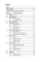
vii About this guide vii P5G41T-M LX Series specifications summary ix Chapter 1: Product introduction 1.1 Welcome 1-1 1.2 Package contents 1-1 1.3 Special features 1-1 1.3.1 Product highlights 1-1 1.3.2 Innovative ASUS features 1-2 1.4 Before you proceed 1-4 1.5 Motherboard overview - Asus P5G41T-M LX PLUS | User Manual - Page 4
an operating system 1-27 1.11.2 Support DVD information 1-27 Chapter 2: BIOS information 2.1 Managing and updating your BIOS 2-1 2.1.1 ASUS Update utility 2-1 2.1.2 ASUS EZ Flash 2 2-2 2.1.3 ASUS CrashFree BIOS 2-3 2.2 BIOS setup program 2-4 2.2.1 BIOS menu screen 2-5 2.2.2 Menu bar - Asus P5G41T-M LX PLUS | User Manual - Page 5
Contents 2.5.4 Anti Surge Support 2-15 2.5.5 APM Configuration 2-16 2.5.6 Hardware Monitor 2-16 2.6 Boot menu 2-17 2.6.1 Boot Device Priority 2-17 2.6.2 Boot Settings Configuration 2-17 2.6.3 Security 2-18 2.7 Tools menu 2-20 2.7.1 ASUS EZ Flash 2 2-20 2.7.2 AI NET 2 2-20 2.8 Exit menu 2- - Asus P5G41T-M LX PLUS | User Manual - Page 6
in accordance with manufacturer's instructions, may cause harmful interference to of the monitor to the graphics card is required to assure compliance with emissions from digital apparatus set out in the Radio ASUS REACH website at http://csr.asus.com/english/REACH.htm. DO NOT throw the motherboard - Asus P5G41T-M LX PLUS | User Manual - Page 7
the motherboard. How this guide is organized This guide contains the following parts: • Chapter 1: Product introduction This chapter describes the features of the motherboard and the new technology it supports. • Chapter 2: BIOS information This chapter tells how to change system settings through - Asus P5G41T-M LX PLUS | User Manual - Page 8
IMPORTANT: Instructions that you MUST follow to complete a task. NOTE: Tips and additional information to help you complete a task. Where to find more information Refer to the following sources for additional information and for product and software updates. 1. ASUS websites The ASUS website - Asus P5G41T-M LX PLUS | User Manual - Page 9
P5G41T-M LX Series specifications summary CPU Chipset Front Side Bus Memory Graphics Expansion slots Storage LAN Audio USB ASUS unique features LGA775 socket for Intel® Core™2 Quad / Core™2 Extreme / Core™2 Duo / Pentium® dual-core / Celeron® dual-core / Celeron® processors Compatible with Intel® - Asus P5G41T-M LX PLUS | User Manual - Page 10
x CPU fan connector 1 x Chassis fan connector 1 x 24-pin EATX power connector 1 x 4-pin ATX 12V power connector 8Mb Flash ROM, AMI BIOS, PnP, DMI 2.0, WfM 2.0, ACPI 2.0a, SM BIOS 2.5 1 x Ultra DMA 100/66/33 cable 2 x Serial ATA cables 1 x I/O shield 1 x User Manual Drivers ASUS utilities ASUS Update - Asus P5G41T-M LX PLUS | User Manual - Page 11
shield ASUS motherboard support DVD User Manual • P5G41T-M LX Series motherboards include P5G41T-M LX V2 and P5G41T-M LX PLUS two models. The package contents vary from models. • If any of the items is damaged or missing, contact your retailer. 1.3 1.3.1 Special features Product highlights Intel - Asus P5G41T-M LX PLUS | User Manual - Page 12
. 100% All High-quality Conductive Polymer Capacitors (P5G41T-M LX PLUS only) This motherboard uses all high-quality conductive polymer capacitors for durability, improved lifespan, and enhanced thermal capacity. Innovative ASUS features ASUS EPU ASUS EPU is a unique power saving technology that - Asus P5G41T-M LX PLUS | User Manual - Page 13
CPU default settings when the system hangs due to overclocking failure. C.P.R. eliminates the need to open the system chassis and clear the RTC data. Simply shut down and reboot the system, and the BIOS automatically restores the CPU parameters to their default settings. ErP ready The motherboard - Asus P5G41T-M LX PLUS | User Manual - Page 14
that the ATX power supply mode, or in soft-off mode. This is a reminder that you must shut down the system and unplug the power cable before removing or plugging in any motherboard component. The illustration below shows the location of the onboard LED. P5G41T-M LX PLUS Onboard LED P5G41T-M LX PLUS - Asus P5G41T-M LX PLUS | User Manual - Page 15
in the image below. 1.5.2 Screw holes Place six screws into the holes indicated by circles to secure the motherboard to the chassis. Do not overtighten the screws! Doing so can damage the motherboard. Place this side towards the rear of the chassis P5G41T-M LX PLUS ASUS P5G41T-M LX Series 1-5 - Asus P5G41T-M LX PLUS | User Manual - Page 16
1.5.3 Motherboard layout ASUS P5G41T-M LX Series motherboards include P5G41T-M LX V2 and P5G41T-M LX PLUS two models. The layout varies with models. The layout illustrations in this user guide are for P5G41T-M LX PLUS only. 20.1cm(7.9in) COM1 P5G41T-M LX PLUS RTL 8111E ICS 9LRS954A4 9 15 14 - Asus P5G41T-M LX PLUS | User Manual - Page 17
. The motherboard supports Intel® LGA775 processors with the Intel® Enhanced Intel SpeedStep® Technology (EIST) and Hyper-Threading Technology. 1.6.1 Installing the CPU To install a CPU: 1. Locate the CPU socket on the motherboard. P5G41T-M LX PLUS P5G41T-M LX PLUS CPU socket 775 Before installing - Asus P5G41T-M LX PLUS | User Manual - Page 18
damage to the socket pins, do not remove the PnP cap unless you are installing a CPU. 3. Lift the load lever in the direction of the arrow to a 135º angle. tab A B Load lever PnP cap Load plate 4B 4A 3 5. Position the CPU over the socket, ensuring that the gold triangle is on the bottom‑left corner - Asus P5G41T-M LX PLUS | User Manual - Page 19
6. Apply some Thermal Interface Material to the exposed area of the CPU that the heatsink will be in contact with, ensuring that it is spread in an even directly. 7. Close the load plate (A), then push the load lever (B) until it snaps into the A retention tab. B ASUS P5G41T-M LX Series 1-9 - Asus P5G41T-M LX PLUS | User Manual - Page 20
condition and performance. • When you buy a boxed Intel® processor, the package includes the CPU fan and heatsink assembly. If you buy a CPU separately, ensure that you use only Intel®‑certified multi‑directional heatsink and fan. • Your Intel® LGA775 heatsink and fan assembly comes in a push-pin - Asus P5G41T-M LX PLUS | User Manual - Page 21
fan cable to the connector on the motherboard labeled CPU_FAN. P5G41T-M LX PLUS P5G41T-M LX PLUS CPU fan connector Do not forget to connect the CPU fan connector! Hardware monitoring errors can occur if you fail to plug this connector. 1.6.3 Uninstalling the CPU heatsink and fan To uninstall the - Asus P5G41T-M LX PLUS | User Manual - Page 22
reinstalling. 1.7 System memory 1.7.1 Overview The motherboard comes with two Double Data Rate 3 (DDR3) Dual Inline Memory Modules (DIMM) sockets. The figure illustrates the location of the DDR3 DIMM sockets: P5G41T-M LX PLUS Channel Channel A Channel B P5G41T-M LX PLUS 240-pin DDR3 DIMM sockets - Asus P5G41T-M LX PLUS | User Manual - Page 23
DIMMs with the same CAS latency. For optimum compatibility, it is recommended that you obtain memory modules support a full memory load (2 DIMMs) or overclocking conditions. P5G41T-M LX Series Motherboard Qualified Vendors Lists DS Hynix H5TQ1G83AFP G7C - - • • ASUS P5G41T-M LX Series 1-13 - Asus P5G41T-M LX PLUS | User Manual - Page 24
3) DS 1024MB SS Micron Micron Micron Micron Qimonda Micron Micron PSC Chip NO. Timing Voltage DIMM socket support (Optional) A* B* AD30908C8D-151C E0906 - - • - 8-8-8-24 1.65-1.85V • AD30908C8D-151C E0903 - - • - 8-8-8-24 1.65-1.85V • - 9-9-9-24 1.60V • - - - • - 9-9-9-24 - Asus P5G41T-M LX PLUS | User Manual - Page 25
support: • A*: Supports one module inserted into any slot as Single-channel memory configuration. • B*: Supports one pair of modules inserted into both the blue slots as one pair of Dual-channel memory configuration. Visit the ASUS website at www.asus.com for the latest QVL. ASUS P5G41T-M LX - Asus P5G41T-M LX PLUS | User Manual - Page 26
components. Failure to do so can cause severe damage to both the motherboard and the components. 1. Press the retaining clips outward to unlock a DIMM Simultaneously press the retaining clips outward to unlock the DIMM. 2 Support the DIMM lightly with your fingers when pressing the retaining 1 - Asus P5G41T-M LX PLUS | User Manual - Page 27
slot This motherboard supports PCI Express x1 network cards, SCSI cards, and other cards that comply with the PCI Express specifications. 1.8.5 PCI Express x16 slot This motherboard supports a PCI Express x16 graphics card that complies with the PCI Express specifications. ASUS P5G41T-M LX Series - Asus P5G41T-M LX PLUS | User Manual - Page 28
include system setup information such as system passwords. P5G41T-M LX PLUS Clear RTC RAM To erase the RTC RAM: overclocking. For system failure due to overclocking, use the CPU Parameter Recall (C.P.R.) feature. Shut down and reboot the system, then the BIOS automatically resets parameter settings - Asus P5G41T-M LX PLUS | User Manual - Page 29
requires an ATX power supply that can supply at least 1A on the +5VSB lead, and a corresponding setting in the BIOS. P5G41T-M LX PLUS Keyboard power setting 3. USB device wake-up (3-pin USBPW1-4, 3-pin USBPW5-8) Set these jumpers to +5V to wake up the computer from S1 sleep mode (CPU stopped, DRAM - Asus P5G41T-M LX PLUS | User Manual - Page 30
ORANGE GREEN Description 10 Mbps connection 100 Mbps connection 1 Gbps connection ACT/LINK SPEED LED LED LAN port 4. Line In port (light blue). This port connects to the tape, CD, DVD HD audio module in the front panel to support 8-channel audio output. 1-20 Chapter 1: Product introduction - Asus P5G41T-M LX PLUS | User Manual - Page 31
, set the Front Panel Type item in the BIOS setup to [HD Audio]. If you want to connect an AC'97 front panel audio module to this connector, set the item to [AC97]. By default, this connector is set to [HD Audio]. See section 2.4.3 Chipset for details. P5G41T-M LX PLUS ASUS P5G41T-M LX Series - Asus P5G41T-M LX PLUS | User Manual - Page 32
motherboard's IDE connector, then select one of the following modes to configure your device. Single device Two devices Drive jumper setting Cable-Select or Master Cable-Select Master Slave Mode IDE devices. P5G41T-M LX PLUS P5G41T-M LX PLUS IDE connector If any device jumper is set as "Cable - Asus P5G41T-M LX PLUS | User Manual - Page 33
firmly until the connectors completely fit. P5G41T-M LX PLUS ATX power connectors • We recommend that you use an ATX 12V Specification 2.0‑compliant power supply unit (PSU) at http://support.asus. com/PowerSupplyCalculator/PSCalculator.aspx?SLanguage=en-us for details. ASUS P5G41T-M LX Series 1-23 - Asus P5G41T-M LX PLUS | User Manual - Page 34
chassis. These USB connectors comply with USB 2.0 specification that supports up to 480 Mbps connection speed. P5G41T-M LX PLUS P5G41T-M LX PLUS USB2.0 connectors Never connect a 1394 cable to the USB connectors. Doing so will damage the motherboard! The USB module cable is purchased separately - Asus P5G41T-M LX PLUS | User Manual - Page 35
air flow inside the system may damage the motherboard components. These are not jumpers! Do not place jumper caps on the fan connectors! P5G41T-M LX PLUS P5G41T-M LX PLUS fan connectors Only the 4-pin CPU fan supports the ASUS Q-FAN feature. 7. Digital audio connector (4-1 pin SPDIF_OUT) This - Asus P5G41T-M LX PLUS | User Manual - Page 36
8. System panel connector (10-1 pin PANEL) This connector supports several chassis-mounted functions. P5G41T-M LX PLUS P5G41T-M LX PLUS System panel connector • System power LED (2-pin PLED) This 2-pin connector is for the system power LED. Connect the chassis power LED cable to this - Asus P5G41T-M LX PLUS | User Manual - Page 37
. Click an icon to display Support DVD/ motherboard information Click an item to install If Autorun is NOT enabled in your computer, browse the contents of the Support DVD to locate the file ASSETUP.EXE from the BIN folder. Double-click the ASSETUP.EXE to run the DVD. ASUS P5G41T-M LX Series 1-27 - Asus P5G41T-M LX PLUS | User Manual - Page 38
1-28 Chapter 1: Product introduction - Asus P5G41T-M LX PLUS | User Manual - Page 39
is available in the support DVD that comes with the motherboard package. Installing ASUS Update To install ASUS Update: 1. Place the support DVD in the optical drive. The Drivers menu appears. 2. Click the Utilities tab, then click ASUS Update. 3. Follow the onscreen instructions to complete the - Asus P5G41T-M LX PLUS | User Manual - Page 40
. Press to switch between drives until the correct BIOS file is found. ASUSTek EZ Flash 2 BIOS ROM Utility V3.36 FLASH TYPE: EON 25P/F80 Current ROM BOARD: P5G41T-M LX PLUS VER: 0301 (H:00 B:00) DATE: 09/17/2010 Update ROM BOARD: Unknown VER: Unknown DATE: Unknown PATH: A:\ A: Note - Asus P5G41T-M LX PLUS | User Manual - Page 41
reset the system while updating the BIOS! Doing so can cause system boot failure! Ensure to load the BIOS default settings to ensure system compatibility and stability. Select the Load Setup Defaults item under the Exit menu. Refer to section 2.8 Exit menu for details. ASUS P5G41T-M LX Series 2-3 - Asus P5G41T-M LX PLUS | User Manual - Page 42
from the operating system. • The default BIOS settings for this motherboard apply for most conditions to ensure optimum performance. If the system becomes unstable after changing any BIOS settings, load the default settings to ensure system compatibility and stability. Select the Load Setups Default - Asus P5G41T-M LX PLUS | User Manual - Page 43
menu screen Menu items Menu bar Main Advanced Power Configuration fields BIOS SETUP UTILITY Boot Tools Exit General help System Time [00 settings. To select an item on the menu bar, press the right or left arrow key on the keyboard until the desired item is highlighted. ASUS P5G41T-M LX - Asus P5G41T-M LX PLUS | User Manual - Page 44
a list of options. Refer to 2.2.7 Pop-up window. 2.2.7 Pop-up window Select a menu item then press to display a pop-up window with the configuration options for that item. Main Advanced BIOS SETUP UTILITY Power Boot Tools Exit Suspend Mode ACPI 2.0 Support ACPI APIC support APM - Asus P5G41T-M LX PLUS | User Manual - Page 45
you are specifically configuring a CD-ROM drive. Select ARMD (ATAPI Removable Media Device) if your device is either a ZIP, LS-120, or MO drive. Configuration options: [Not Installed] [Auto] [CDROM] [ARMD] This item does not appear when you select the SATA 1/2/3/4 devices. ASUS P5G41T-M LX Series - Asus P5G41T-M LX PLUS | User Manual - Page 46
the item. ATA/IDE Configuration [Enhanced] Allows you to set the ATA/IDE configuration. Configuration options: [Disabled] [Compatible] [Enhanced] Enhanced Mode Support On [S-ATA] Sets Serial ATA, Parallel ATA or both as native mode. Configuration options: [S-ATA+P-ATA] [S-ATA] [P-ATA]. IDE Detect - Asus P5G41T-M LX PLUS | User Manual - Page 47
of the preset overclocking configuration options: Manual - allows you to individually set overclocking parameters. Auto - loads the optimal settings for the system. Overclock Profile - loads overclocking profiles with optimal parameters for stability when overclocking. ASUS P5G41T-M LX Series 2-9 - Asus P5G41T-M LX PLUS | User Manual - Page 48
two items appear only when you set the AI Overclocking item to [MANUAL]. CPU Frequency [xxx] Displays the frequency sent by the clock generator to the system bus and PCI bus. The value of this item is auto-detected by the BIOS. Use the and keys to adjust the CPU frequency. You can also type - Asus P5G41T-M LX PLUS | User Manual - Page 49
enhanced by Intel® Virtualization Technology allows a platform to run multiple operating systems and applications in independent partitions. With virtualization, one computer system can function as multiple virtual systems. Configuration options: [Enabled] [Disabled] ASUS P5G41T-M LX Series 2-11 - Asus P5G41T-M LX PLUS | User Manual - Page 50
Intel® Pentium® 4 or later CPU that supports the Enhanced Intel SpeedStep® Technology (EIST). Intel(R) SpeedStep(TM) Tech [Enabled] Allows you to use the Enhanced Intel® SpeedStep® Technology. When set the advanced chipset settings. Select an item [PEG/PCI] IGD Graphics Mode Select [Enabled, 32MB] - Asus P5G41T-M LX PLUS | User Manual - Page 51
ECP DMA. Configuration options: [DMA0] [DMA1] [DMA3] EPP Version [1.9] Appears only when the Parallel Port Mode is set to [EPP]. Configuration options: [1.9] [1.7] Parallel Port IRQ [IRQ7] Allows you to select parallel port IRQ. Configuration options: [IRQ5] [IRQ7] ASUS P5G41T-M LX Series 2-13 - Asus P5G41T-M LX PLUS | User Manual - Page 52
Storage Reset Delay [20 Sec] Allows you to set the maximum time that the BIOS waits for the USB storage device to initialize. Configuration options: [10 Sec] [20 Sec] [30 Sec] [40 Sec] Emulation Type [Auto] Allows you to select the emulation type. Configuration options: [Auto] [Floppy] [Forced FDD - Asus P5G41T-M LX PLUS | User Manual - Page 53
ASIC). When set to Enabled, the ACPI APIC table pointer is included in the RSDT pointer list. Configuration options: [Disabled] [Enabled] 2.5.4 Anti Surge Support [Enabled] Allows you to enable or disable the Anti-Surge protection. Configuration options: [Disabled] [Enabled] ASUS P5G41T-M LX Series - Asus P5G41T-M LX PLUS | User Manual - Page 54
a call while the computer is in Soft-off mode. Configuration options: [Disabled] [Enabled] Power On By PCI (E) Device [Disabled] When set to [Enabled], this parameter allows you to wake the system through a PCI Express/ PCI card. This feature requires an ATX power supply that provides at least 1A on - Asus P5G41T-M LX PLUS | User Manual - Page 55
Settings Configuration Quick Boot [Enabled] Enabling this item allows the BIOS to skip some power on self tests (POST) while booting to decrease the time needed to boot the system. When set to [Disabled], BIOS performs all the POST items. Configuration options: [Disabled] [Enabled] ASUS P5G41T-M LX - Asus P5G41T-M LX PLUS | User Manual - Page 56
Set this item to [Enabled] to use the ASUS MyLogo2™ feature. AddOn ROM Display Mode [Force BIOS] Sets the display mode for option ROM. Configuration options: [Force BIOS DEL' Message Display [Enabled] When set to [Enabled], the system displays the message Press DEL to run Setup during POST. - Asus P5G41T-M LX PLUS | User Manual - Page 57
the user password. Password Check [Setup] When set to [Setup], BIOS checks for user password when accessing the Setup utility. When set to [Always], BIOS checks for user password both when accessing Setup and booting the system. Configuration options: [Setup] [Always] ASUS P5G41T-M LX Series 2-19 - Asus P5G41T-M LX PLUS | User Manual - Page 58
2 Press ENTER to run the utility to select and update BIOS. This utility supports 1.FAT 12/16/32 (r/w) 2.NTFS (read only) 3.CD-DISC (read only) 2.7.1 ASUS EZ Flash 2 Allows you to run ASUS EZ Flash 2. When you press , a confirmation message appears. Use the left/right arrow key to select - Asus P5G41T-M LX PLUS | User Manual - Page 59
program. If you made changes to fields other than System Date, System Time, and Password, the BIOS asks for a confirmation before exiting. Discard Changes This option allows you to discard the selections you changes before saving the values to the non-volatile RAM. ASUS P5G41T-M LX Series 2-21 - Asus P5G41T-M LX PLUS | User Manual - Page 60
2-22 Chapter 2: BIOS information - Asus P5G41T-M LX PLUS | User Manual - Page 61
15 Li-Te Road, Peitou, Taipei, Taiwan 11259 +886-2-2894-3447 +886-2-2890-7798 [email protected] www.asus.com.tw Technical Support Telephone Online support +86-21-38429911 support.asus.com ASUS COMPUTER INTERNATIONAL (America) Address 800 Corporate Way, Fremont, CA 94539, USA Telephone - Asus P5G41T-M LX PLUS | User Manual - Page 62
Responsible Party Name: Asus Computer International Address: 800 Corporate Way, Fremont, CA 94539. Phone/Fax No: (510)739-3777/(510)608-4555 hereby declares that the product Product Name : Motherboard Model Number : P5G41T-M LX PLUS, P5G41T-M LX V2 Conforms to the following specifications: FCC Part
-
 1
1 -
 2
2 -
 3
3 -
 4
4 -
 5
5 -
 6
6 -
 7
7 -
8
-
9
-
10
-
11
-
12
-
13
-
14
-
15
-
16
-
17
-
18
-
19
-
20
-
21
-
22
-
23
-
24
-
25
-
26
-
27
-
28
-
29
-
30
-
31
-
32
-
33
-
34
-
35
-
36
-
37
-
38
-
39
-
40
-
41
-
42
-
43
-
44
-
45
-
46
-
47
-
48
-
49
-
50
-
51
-
52
-
53
-
54
-
55
-
56
-
57
-
58
-
59
-
60
-
61
-
62
 |
 |

Motherboard
P5G41T-M LX V2
P5G41T-M LX PLUS