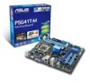
Asus P5G41T-M User Manual
Asus P5G41T-M Manual
 |
View all Asus P5G41T-M manuals
Add to My Manuals
Save this manual to your list of manuals |
Asus P5G41T-M manual content summary:
- Asus P5G41T-M | User Manual - Page 1
P5G41T-M Motherboard - Asus P5G41T-M | User Manual - Page 2
express written permission of ASUSTeK Computer Inc. ("ASUS"). Product warranty or service will not be extended if: (1) the ASUS HAS BEEN ADVISED OF THE POSSIBILITY OF SUCH DAMAGES ARISING FROM ANY DEFECT OR ERROR IN THIS MANUAL OR PRODUCT. SPECIFICATIONS AND INFORMATION CONTAINED IN THIS MANUAL - Asus P5G41T-M | User Manual - Page 3
About this guide vii P5G41T-M specifications summary ix Chapter 1: Product introduction 1.1 Welcome 1-1 1.2 Package contents 1-1 1.3 Special features 1-1 1.3.1 Product highlights 1-1 1.3.2 Innovative ASUS features 1-2 1.4 Before you proceed 1-4 1.5 Motherboard overview 1-5 1.5.1 Placement - Asus P5G41T-M | User Manual - Page 4
an operating system 1-26 1.11.2 Support DVD information 1-26 Chapter 2: BIOS information 2.1 Managing and updating your BIOS 2-1 2.1.1 ASUS Update utility 2-1 2.1.2 ASUS EZ Flash 2 2-2 2.1.3 ASUS CrashFree BIOS 2-3 2.2 BIOS setup program 2-4 2.2.1 BIOS menu screen 2-5 2.2.2 Menu bar - Asus P5G41T-M | User Manual - Page 5
Contents 2.5.4 Anti Surge Support 2-15 2.5.5 APM Configuration 2-16 2.5.6 Hardware Monitor 2-16 2.6 Boot menu 2-17 2.6.1 Boot Device Priority 2-17 2.6.2 Boot Settings Configuration 2-17 2.6.3 Security 2-18 2.7 Tools menu 2-20 2.7.1 ASUS EZ Flash 2 2-20 2.7.2 Express Gate 2-20 2.7.3 AI NET - Asus P5G41T-M | User Manual - Page 6
and, if not installed and used in accordance with manufacturer's instructions, may cause harmful interference to radio communications. However, there substances in our products at ASUS REACH website at http://green.asus.com/english/REACH.htm. DO NOT throw the motherboard in municipal waste. This - Asus P5G41T-M | User Manual - Page 7
. • If you encounter technical problems with the product, contact a qualified service technician or your retailer. About this guide This user guide contains the information you need when installing and configuring the motherboard. How this guide is organized This guide contains the following parts - Asus P5G41T-M | User Manual - Page 8
IMPORTANT: Instructions that you MUST follow to complete a task. NOTE: Tips and additional information to help you complete a task. Where to find more information Refer to the following sources for additional information and for product and software updates. 1. ASUS websites The ASUS website - Asus P5G41T-M | User Manual - Page 9
P5G41T-M specifications summary CPU Chipset Front Side Bus Memory Graphics Expansion slots Storage LAN Audio USB LGA775 socket for Intel® Core™2 Quad / Core™2 Extreme / Core™2 Duo / Pentium® dual-core / Celeron® dual-core / Celeron® processors Supports Intel® 45nm multi-core CPU Supports Intel® - Asus P5G41T-M | User Manual - Page 10
ACPI 2.0a, SM BIOS 2.5 WOL, PXE, WOR by Ring, PME Wake up 1 x Ultra DMA 100/66/33 cable 2 x Serial ATA cables 1 x I/O shield 1 x User Manual Drivers ASUS PC Probe II ASUS Update Anti-Virus software (OEM version) uATX form factor: 9.6 in x 8 in (24.4 cm x 20.3 cm) * Specifications are subject to - Asus P5G41T-M | User Manual - Page 11
CPU support This motherboard supports Intel® LGA775 Core™ 2 Extreme / Core™ 2 Quad/ Core™ 2 Duo processors, which are excellent for multitasking, multimedia, and enthusiastic gamers with 1333/1066/800 MHz FSB. This motherboard also supports Intel® CPUs in the 45nm manufacturing process. ASUS P5G41T - Asus P5G41T-M | User Manual - Page 12
ATA 3Gb/s technology This motherboard supports hard drives based on the Serial ATA (SATA) 3Gb/s storage specifications, delivering enhanced scalability and to save power and money. Turbo Key ASUS Turbo Key allows you to turn the PC power button into an overclocking button. After you easy setup, Turbo - Asus P5G41T-M | User Manual - Page 13
the drives to the motherboard USB port before turning on the computer. • The actual boot time depends on the system configuration. • ASUS Express Gate supports file uploading from SATA HDDs, ODDs and USB drives. It supports file downloading to USB drives only. ASUS MyLogo2™ This feature allows - Asus P5G41T-M | User Manual - Page 14
switched off or the power cord is detached from the power supply. Failure to do so may cause severe damage to the motherboard, peripherals, or components. Onboard LED The motherboard comes with a standby power LED that lights up to indicate that the system is ON, in sleep mode, or in soft-off - Asus P5G41T-M | User Manual - Page 15
of the chassis as indicated in the image below. 1.5.2 Screw holes Place six screws into the holes indicated by circles to secure the motherboard to the chassis. Do not overtighten the screws! Doing so can damage the motherboard. Place this side towards the rear of the chassis ASUS P5G41T-M 1-5 - Asus P5G41T-M | User Manual - Page 16
1.5.3 Motherboard layout 1.5.4 Layout contents Connectors/Jumpers/Slots/LED 1. ATX power connectors (24-pin EATXPWR, 4-pin ATX12V) 2. CPU and chassis fan connectors (4-pin CPU_FAN, 3-pin CHA_FAN) 3. Intel LGA775 CPU socket 4. DDR3 DIMM slots 5. IDE connector (40-1 pin PRI_IDE) 6. Clear RTC RAM (3- - Asus P5G41T-M | User Manual - Page 17
/incorrect removal of the PnP cap. The motherboard supports Intel® LGA775 processors with the Intel® Enhanced Intel SpeedStep® Technology CPU socket on the motherboard. Before installing the CPU, ensure that the cam box is facing towards you and the load lever is on your left. ASUS P5G41T-M 1-7 - Asus P5G41T-M | User Manual - Page 18
to a 135º angle. 4. Lift the load plate with your thumb and forefinger to a 100º angle (4A), then push the PnP cap from the load plate window to remove (4B). Retention tab A B Load lever PnP cap Load plate 4B 4A 3 5. Position the CPU over the socket, ensuring that the gold triangle is - Asus P5G41T-M | User Manual - Page 19
, DO NOT spread the paste with your finger directly. 7. Close the load plate (A), then push the load lever (B) until it snaps into the A retention tab. B ASUS P5G41T-M 1-9 - Asus P5G41T-M | User Manual - Page 20
condition and performance. • When you buy a boxed Intel® processor, the package includes the CPU fan and heatsink assembly. If you of the installed CPU, ensuring that the four fasteners match the holes on the motherboard. Orient the heatsink and fan assembly such that the CPU fan cable is closest - Asus P5G41T-M | User Manual - Page 21
heatsink and fan: 1. Disconnect the CPU fan cable from the connector on the motherboard. 2. Rotate each fastener counterclockwise. 3. Pull up two fasteners at a time in a diagonal sequence to disengage the heatsink and fan assembly from the motherboard. A A B B B A B A ASUS P5G41T-M 1-11 - Asus P5G41T-M | User Manual - Page 22
. 5. Rotate each fastener clockwise to ensure correct orientation when reinstalling. 1.7 System memory 1.7.1 Overview The motherboard comes with two Double Data Rate 3 (DDR3) Dual Inline Memory Modules (DIMM) sockets. The figure illustrates the location of the DDR3 DIMM sockets: Channel Channel - Asus P5G41T-M | User Manual - Page 23
limitation on 32-bit Windows® OS, when you install 4GB or more memory on the motherboard, the actual usable memory support a full memory load (2 DIMMs) or overclocking conditions. P5G41T-M Motherboard SEC 901 HCF8 K4B1G0846E - - • • SAMSUNG 846 K4B2G0846B-HCF8 -- • • ASUS P5G41T-M 1-13 - Asus P5G41T-M | User Manual - Page 24
one module inserted into any slot as Single-channel memory configuration. • B*: Supports one pair of modules inserted into both the blue slots as one pair of Dual-channel memory configuration. Visit the ASUS website at www.asus.com for the latest QVL. 1-14 Chapter 1: Product introduction - Asus P5G41T-M | User Manual - Page 25
can cause severe damage to both the motherboard and the components. To install a DIMM Support the DIMM lightly with your fingers when pressing the retaining clips. The DIMM might get damaged when it flips out with extra force. 1 2. Remove the DIMM from the socket. 2 1 DDR3 DIMM notch ASUS P5G41T - Asus P5G41T-M | User Manual - Page 26
system unstable and the card inoperable. 1.8.3 PCI slots The PCI slots support cards such as a LAN card, SCSI card, USB card, and other cards that comply with PCI specifications. 1.8.4 PCI Express x1 slot This motherboard supports PCI Express x1 network cards, SCSI cards, and other cards that comply - Asus P5G41T-M | User Manual - Page 27
and enter BIOS setup to re-enter data. Except when clearing the RTC RAM, never overclocking. For system failure due to overclocking, use the CPU Parameter Recall (C.P.R.) feature. Shut down and reboot the system, then the BIOS automatically resets parameter settings to default values. ASUS P5G41T - Asus P5G41T-M | User Manual - Page 28
ORANGE GREEN Description 10 Mbps connection 100 Mbps connection 1 Gbps connection ACT/LINK SPEED LED LED LAN port 3. Line In port (light blue). This port connects to the tape, CD, DVD audio module in the front panel to support 8-channel audio output. 1-18 Chapter 1: Product introduction - Asus P5G41T-M | User Manual - Page 29
I/O module that supports either HD Audio of the motherboard's high- BIOS setup to [HD Audio]. If you want to connect an AC'97 front panel audio module to this connector, set the item to [AC97]. By default, this connector is set to [HD Audio]. See section 2.4.3 Chipset for details. ASUS P5G41T - Asus P5G41T-M | User Manual - Page 30
the fan connectors. Insufficient air flow inside the system may damage the motherboard components. These are not jumpers! Do not place jumper caps on the fan connectors! Only the 4-pin CPU fan supports the ASUS Q-FAN feature. 3. Digital audio connector (4-1 pin SPDIF_OUT) This connector is for an - Asus P5G41T-M | User Manual - Page 31
firmly until the connectors completely fit. • We recommend that you use an ATX 12V Specification 2.0‑compliant power supply unit (PSU) with a minimum of 400W power rating. This at http://support.asus. com/PowerSupplyCalculator/PSCalculator.aspx?SLanguage=en-us for details. ASUS P5G41T-M 1-21 - Asus P5G41T-M | User Manual - Page 32
. The Serial ATA 3Gb/s is backward compatible with Serial ATA 1.5Gb/s specification. The data transfer rate of the Serial ATA 3Gb/s is faster than the standard parallel ATA with 133 MB/s (Ultra DMA133). Install the Windows® XP Service Pack 2 or later version before using Serial ATA. 6. LPT connector - Asus P5G41T-M | User Manual - Page 33
DMA 100/66/33 signal cable: blue, black, and gray. Connect the blue connector to the motherboard's IDE connector, then select one of the following modes to configure your device. Single device Two devices -Select," ensure that all other device jumpers have the same setting. ASUS P5G41T-M 1-23 - Asus P5G41T-M | User Manual - Page 34
System panel connector (20-8 pin PANEL) This connector supports several chassis-mounted functions. • System power LED (2- turns the system on or puts the system in sleep or soft-off mode depending on the BIOS settings. Pressing the power switch for more than four seconds while the system is ON turns - Asus P5G41T-M | User Manual - Page 35
at the back of the system chassis. These USB connectors comply with USB 2.0 specification that supports up to 480 Mbps connection speed. Never connect a 1394 cable to the USB connectors. Doing so will damage the motherboard! The USB module cable is purchased separately. 10. Serial port connector (10 - Asus P5G41T-M | User Manual - Page 36
to avail all motherboard features. The contents of the Support DVD are subject to change at any time without notice. Visit the ASUS website at www.asus.com for updates. To run the Support DVD Place the Support DVD to the optical drive. The DVD automatically displays the Drivers menu if Autorun - Asus P5G41T-M | User Manual - Page 37
with the motherboard package. Installing ASUS Update To install ASUS Update: 1. Place the support DVD in the optical drive. The Drivers menu appears. 2. Click the Utilities tab, then click ASUS Update. 3. Follow the onscreen instructions to complete the installation. Quit all Windows® applications - Asus P5G41T-M | User Manual - Page 38
onscreen instructions to complete the updating process. 2.1.2 ASUS EZ Flash 2 The ASUS EZ Flash 2 feature allows you to update the BIOS without using an OS‑based utility. Before you start using this utility, download the latest BIOS file from the ASUS website at www.asus.com. To update the BIOS - Asus P5G41T-M | User Manual - Page 39
into P5G41TM.ROM. • The BIOS file in the support DVD may not be the latest version. Download the latest BIOS file from the ASUS website at www.asus.com. • The removable devices that ASUS CrashFree BIOS support vary with motherboard models. For motherboards without the floppy connector, prepare - Asus P5G41T-M | User Manual - Page 40
Menu. See section 2.8 Exit Menu. • The BIOS setup screens shown in this section are for reference purposes only, and may not exactly match what you see on your screen. • Visit the ASUS website at www.asus.com to download the latest BIOS file for this motherboard. 2-4 Chapter 2: BIOS information - Asus P5G41T-M | User Manual - Page 41
menu screen Menu items Menu bar Main Advanced Power Configuration fields BIOS SETUP UTILITY Boot Tools Exit General help System Time [00:31:48] System Date [Fri 01/25/2002] Use bar, press the right or left arrow key on the keyboard until the desired item is highlighted. ASUS P5G41T-M 2-5 - Asus P5G41T-M | User Manual - Page 42
Menu items The highlighted item on the menu bar displays the specific items for that menu. For example, selecting Main shows the Main window with the configuration options for that item. Main Advanced BIOS SETUP UTILITY Power Boot Tools Exit Suspend Mode ACPI 2.0 Support ACPI APIC support - Asus P5G41T-M | User Manual - Page 43
the BIOS specifically configuring a CD-ROM drive. Select ARMD (ATAPI Removable Media Device) if your device is either a ZIP, LS-120, or MO drive. Configuration options: [Not Installed] [Auto] [CDROM] [ARMD] This item does not appear when you select the SATA 1/2/3/4 devices. ASUS P5G41T - Asus P5G41T-M | User Manual - Page 44
the data transfer from and to the device occurs multiple sectors at a time if the device supports multi-sector transfer feature. When set to [Disabled], the data transfer from and to the device devices. Configuration options: [0] [5] [10] [15] [20] [25] [30] [35] 2-8 Chapter 2: BIOS information - Asus P5G41T-M | User Manual - Page 45
either one of the preset overclocking configuration options: Manual - allows you to individually set overclocking parameters. Auto - loads the optimal settings for the system. Overclock Profile - loads overclocking profiles with optimal parameters for stability when overclocking. ASUS P5G41T-M 2-9 - Asus P5G41T-M | User Manual - Page 46
The following two items appear only when you set the AI Overclocking item to [MANUAL]. CPU Frequency [xxx] Displays the frequency sent by the clock generator to the system bus and PCI bus. The value of this item is auto-detected by the BIOS. Use the and keys to adjust the CPU frequency. You - Asus P5G41T-M | User Manual - Page 47
the BIOS automatically Support. Configuration options: [Disabled] [Enabled] Max CPUID Value Limit [Disabled] Setting this item to [Enabled] allows legacy operating systems to boot even without support for CPUs with extended CPUID functions. Configuration options: [Disabled] [Enabled] ASUS P5G41T - Asus P5G41T-M | User Manual - Page 48
following item appears only when you installed an Intel® Pentium® 4 or later CPU that supports the Enhanced Intel SpeedStep® Technology (EIST). Intel(R) SpeedStep(TM) Tech [Enabled] Allows you 32MB] [Enabled, 48MB] [Enabled, 64MB] [Enabled, 128MB] [Enabled, 256MB] 2-12 Chapter 2: BIOS information - Asus P5G41T-M | User Manual - Page 49
Panel Type [HD Audio] Allows you to select the front panel support type. If High Definition Audio Front Panel used, set this item disable the boot ROM in the onboard LAN controller. This item appears only when the Onboard LAN item is set to Enabled. Configuration [IRQ5] [IRQ7] ASUS P5G41T-M 2-13 - Asus P5G41T-M | User Manual - Page 50
mode is enabled. If no USB device is detected, the legacy USB support is disabled. Configuration options: [Disabled] [Enabled] [Auto] USB 2.0 Reset Delay [20 Sec] Allows you to set the maximum time that the BIOS waits for the USB storage device to initialize. Configuration options: [10 Sec] [20 - Asus P5G41T-M | User Manual - Page 51
Play O/S [No] When set to [No], BIOS configures all the devices in the system. When set Interface (ACPI) support in the Application-Specific Integrated Circuit (ASIC Support [Enabled] Allows you to enable or disable the Anti-Surge protection. Configuration options: [Disabled] [Enabled] ASUS P5G41T - Asus P5G41T-M | User Manual - Page 52
On By PS/2 Keyboard [Disabled] Allows you to use specific keys on the keyboard to turn on the system. This monitor automatically detects and displays the motherboard and CPU temperatures. Select Ignored if ). If the fan is not connected to the motherboard, the field shows N/A. Select Ignored if you - Asus P5G41T-M | User Manual - Page 53
Configuration Quick Boot [Enabled] Enabling this item allows the BIOS to skip some power on self tests (POST) while booting to decrease the time needed to boot the system. When set to [Disabled], BIOS performs all the POST items. Configuration options: [Disabled] [Enabled] ASUS P5G41T-M 2-17 - Asus P5G41T-M | User Manual - Page 54
] to use the ASUS MyLogo2™ feature. AddOn ROM Display Mode [Force BIOS] Sets the display mode for option ROM. Configuration options: [Force BIOS] [Keep Current] appears. If you forget your BIOS password, you can clear it by erasing the CMOS Real Time Clock (RTC) RAM. See section 1.9 Jumpers for - Asus P5G41T-M | User Manual - Page 55
to clear the user password. Password Check [Setup] When set to [Setup], BIOS checks for user password when accessing the Setup utility. When set to [Always], BIOS checks for user password both when accessing Setup and booting the system. Configuration options: [Setup] [Always] ASUS P5G41T-M 2-19 - Asus P5G41T-M | User Manual - Page 56
update BIOS. This utility supports 1.FAT 12/16/32 (r/w) 2.NTFS (read only) 3.CD-DISC (read only) 2.7.1 ASUS EZ Flash 2 Allows you to run ASUS Express Gate's first screen before starting Windows or other installed OS. Choose [Prompt LAN cable [Disabled] Enables or disables checking of the Atheros LAN - Asus P5G41T-M | User Manual - Page 57
Discard Changes Load Setup Defaults BIOS SETUP UTILITY Boot Tools Exit you press , a confirmation window appears. Select OK to load default values. Select Exit & Save Changes or make other changes before saving the values to the non-volatile RAM. ASUS P5G41T-M 2-21 - Asus P5G41T-M | User Manual - Page 58
2-22 Chapter 2: BIOS information
-
 1
1 -
 2
2 -
 3
3 -
 4
4 -
 5
5 -
 6
6 -
 7
7 -
8
-
9
-
10
-
11
-
12
-
13
-
14
-
15
-
16
-
17
-
18
-
19
-
20
-
21
-
22
-
23
-
24
-
25
-
26
-
27
-
28
-
29
-
30
-
31
-
32
-
33
-
34
-
35
-
36
-
37
-
38
-
39
-
40
-
41
-
42
-
43
-
44
-
45
-
46
-
47
-
48
-
49
-
50
-
51
-
52
-
53
-
54
-
55
-
56
-
57
-
58
 |
 |

Motherboard
P5G41T-M