Asus P5GD1-VM P5GD1-VM User's manual English Edition E1881 - Page 25
System memory - chipset
 |
View all Asus P5GD1-VM manuals
Add to My Manuals
Save this manual to your list of manuals |
Page 25 highlights
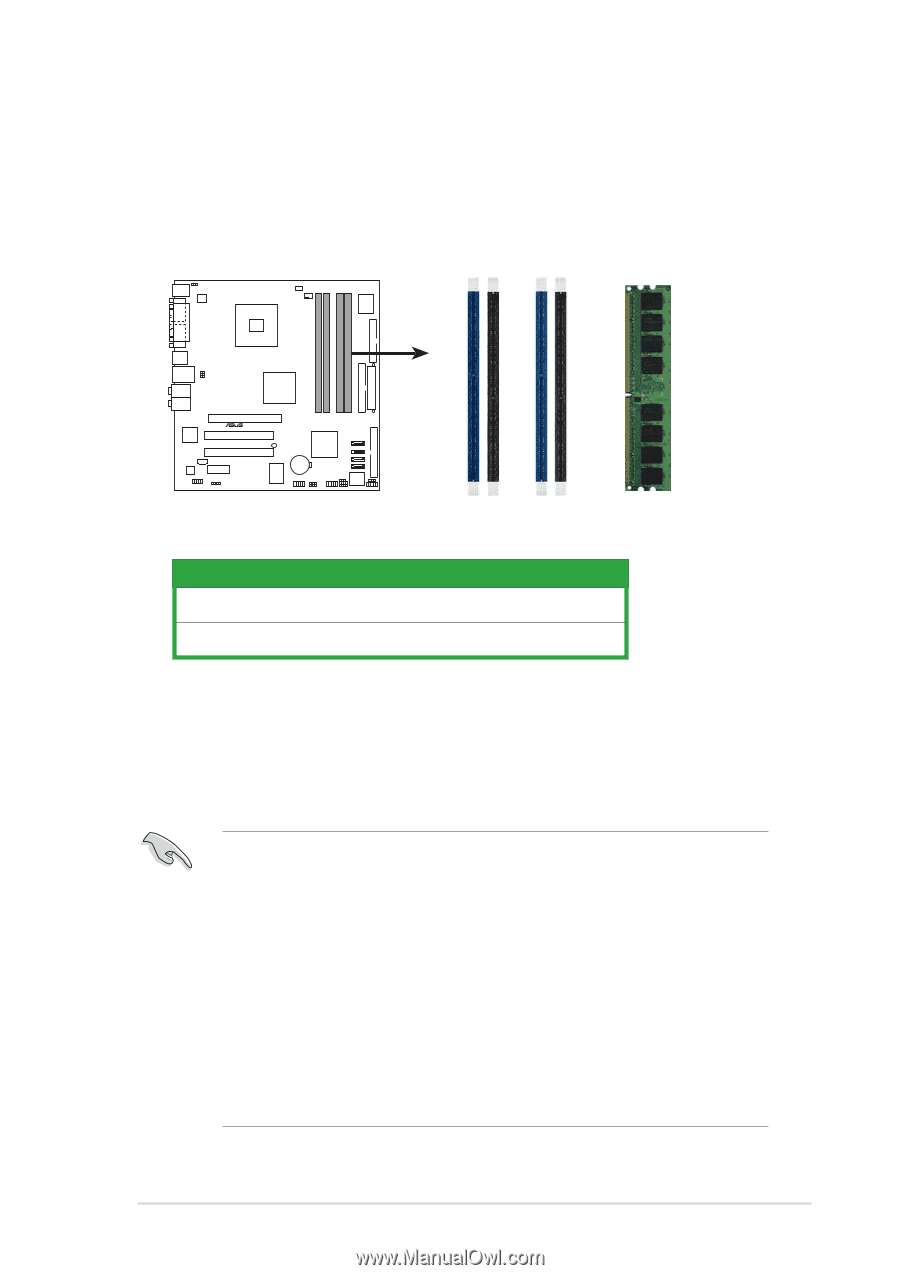
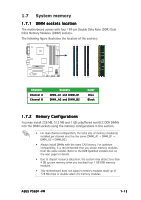
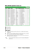
1.7 System memory 1.7.1 DIMM sockets location The motherboard comes with four 184-pin Double Data Rate (DDR) Dual Inline Memory Modules (DIMM) sockets. The following figure illustrates the location of the sockets: P5GD1-VM DIMM_A1 DIMM_A2 DIMM_B1 DIMM_B2 ® P5GD1-VM 184-Pin DDR DIMM Sockets Channel Channel A Channel B Sockets DIMM_A1 and DIMM_B1 DIMM_A2 and DIMM_B2 Color Blue Black 1.7.2 Memory Configurations You may install 256 MB, 512 MB and 1 GB unbuffered non-ECC DDR DIMMs into the DIMM sockets using the memory configurations in this section. • For dual-channel configuration, the total size of memory module(s) installed per channel must be the same (DIMM_A1 + DIMM_B1 = DIMM_A2 + DIMM_B2). • Always install DIMMs with the same CAS latency. For optimum compatibility, it is recommended that you obtain memory modules from the same vendor. Refer to the DDR Qualified Vendors List on the next page for details. • Due to chipset resource allocation, the system may detect less than 4 GB system memory when you installed four 1 GB DDR memory modules. • This motherboard does not support memory modules made up of 128 Mb chips or double sided x16 memory modules. ASUS P5GD1-VM 1-15
-
 1
1 -
2
-
3
-
4
-
5
-
6
-
7
-
8
-
9
-
10
-
11
-
12
-
13
-
14
-
15
-
16
-
17
-
18
-
19
-
 20
20 -
 21
21 -
 22
22 -
 23
23 -
 24
24 -
 25
25 -
 26
26 -
 27
27 -
 28
28 -
 29
29 -
 30
30 -
31
-
32
-
33
-
34
-
35
-
36
-
37
-
38
-
39
-
40
-
41
-
42
-
43
-
44
-
45
-
46
-
47
-
48
-
49
-
50
-
51
-
52
-
53
-
54
-
55
-
56
-
57
-
58
-
59
-
60
-
61
-
62
-
63
-
64
-
65
-
66
-
67
-
68
-
69
-
70
-
71
-
72
-
73
-
74
-
75
-
76
-
77
-
78
-
79
-
80
-
81
-
82
-
83
-
84
-
85
-
86
-
87
-
88
-
89
-
90
-
91
-
92
 |
 |