Asus P5GD1 P5GD1 User's Manual English Version E1673
Asus P5GD1 Manual
 |
View all Asus P5GD1 manuals
Add to My Manuals
Save this manual to your list of manuals |
Asus P5GD1 manual content summary:
- Asus P5GD1 | P5GD1 User's Manual English Version E1673 - Page 1
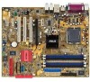
P5GD1 Motherboard - Asus P5GD1 | P5GD1 User's Manual English Version E1673 - Page 2
express written permission of ASUSTeK COMPUTER INC. ("ASUS"). Product warranty or service will not be extended if: (1) the ASUS HAS BEEN ADVISED OF THE POSSIBILITY OF SUCH DAMAGES ARISING FROM ANY DEFECT OR ERROR IN THIS MANUAL OR PRODUCT. SPECIFICATIONS AND INFORMATION CONTAINED IN THIS MANUAL - Asus P5GD1 | P5GD1 User's Manual English Version E1673 - Page 3
viii About this guide ix Typography x P5GD1 specifications summary xi Chapter 1: Product introduction 1.1 Welcome 1-1 1.2 Package contents 1-1 1.3 Special features 1-2 1.3.1 Product highlights 1-2 1.3.2 ASUS Proactive features 1-4 1.3.3 Innovative ASUS features 1-4 Chapter 2: Hardware - Asus P5GD1 | P5GD1 User's Manual English Version E1673 - Page 4
power switch 3-2 Chapter 4: BIOS setup 4.1 Managing and updating your BIOS 4-1 4.1.1 Creating a bootable floppy disk 4-1 4.1.2 ASUS EZ Flash utility 4-2 4.1.3 AFUDOS utility 4-3 4.1.4 ASUS CrashFree BIOS 2 utility 4-5 4.1.5 ASUS Update utility 4-7 4.2 BIOS setup program 4-10 4.2.1 BIOS - Asus P5GD1 | P5GD1 User's Manual English Version E1673 - Page 5
4-37 4.7 Exit menu 4-39 Chapter 5: Software support 5.1 Installing an operating system 5-1 5.2 Support CD information 5-1 5.2.1 Running the support CD 5-1 5.2.2 Drivers menu 5-2 5.2.3 Utilities menu 5-3 5.2.4 Manuals menu 5-5 5.2.5 ASUS Contact information 5-6 5.2.6 Other information - Asus P5GD1 | P5GD1 User's Manual English Version E1673 - Page 6
Contents 5.3.2 AI Net 2 5-10 Using the Virtual Cable Tester 5-10 5.3.3 Audio configurations 5-11 5.4 RAID configurations 5-16 5.4.1 Installing hard disks 5-17 5.4.2 Intel® RAID configurations 5-18 5.4.3 ITE® 8212F RAID configurations 5-22 5.5 Creating a RAID driver disk 5-28 vi - Asus P5GD1 | P5GD1 User's Manual English Version E1673 - Page 7
, if not installed and used in accordance with manufacturer's instructions, may cause harmful interference to radio communications. However, there the dealer or an experienced radio/TV technician for help. The use of shielded cables for connection of the monitor to the graphics card is required to - Asus P5GD1 | P5GD1 User's Manual English Version E1673 - Page 8
are using, contact your local power company. • If the power supply is broken, do not try to fix it by yourself. Contact a qualified service technician or your retailer. Operation safety • Before installing the motherboard and adding devices on it, carefully read all the manuals that came with the - Asus P5GD1 | P5GD1 User's Manual English Version E1673 - Page 9
you need when installing and configuring the motherboard. How this guide is organized This manual contains the following parts: • Chapter 1: Product introduction This chapter describes the features of the motherboard and the new technology it supports. • Chapter 2: Hardware information This chapter - Asus P5GD1 | P5GD1 User's Manual English Version E1673 - Page 10
manual. D A N G E R / W A R N I N G : Information to prevent injury to yourself when trying to complete a task. C A U T I O N : Information to prevent damage to the components when trying to complete a task. I M P O R T A N T : Instructions exactly as shown, then supply the required item or value - Asus P5GD1 | P5GD1 User's Manual English Version E1673 - Page 11
P5GD1 specifications summary CPU LGA775 socket for Intel® Pentium® 4/Celeron processor Compatible with the Intel® PCG 04A and 04B processors Supports Intel® Hyper-Threading Technology Chipset Northbridge: Intel® 915P Memory Controller Hub (MCH) Southbridge: Intel® ICH6R F r o n t S i d e B u s - Asus P5GD1 | P5GD1 User's Manual English Version E1673 - Page 12
x Front panel audio connector System panel connector ATX power supply (with 24-pin and 4-pin 12 V plugs) ATX 12 V 2.0 compliant ATX form factor: 12 in x 9.6 in (30.5 cm x 24.4 cm) Device drivers ASUS PC Probe ASUS Live Update utility Anti-virus software (OEM version) *Specifications are subject to - Asus P5GD1 | P5GD1 User's Manual English Version E1673 - Page 13
This chapter describes the motherboard features and the new technologies it supports. 1Product introduction - Asus P5GD1 | P5GD1 User's Manual English Version E1673 - Page 14
Chapter summary 1.1 Welcome 1-1 1.2 Package contents 1-1 1.3 Special features 1-2 ASUS P5GD1 - Asus P5GD1 | P5GD1 User's Manual English Version E1673 - Page 15
1 x Serial ATA power cables 1 x Ultra DMA/133 cables 1 x IDE cable Floppy disk drive cable Accessories I/O shield A p p l i c a t i o n C D s ASUS motherboard support CD D o c u m e n t a t i o n User guide If any of the above items is damaged or missing, contact your retailer. ASUS P5GD1 1-1 - Asus P5GD1 | P5GD1 User's Manual English Version E1673 - Page 16
core speed of up to 3.6 GHz. The motherboard also supports the Intel ® Hyper-Threading Technology and is fully compatible with Intel® 04B and 04A processors. See page 2-6 for details. Intel® 915P The Intel® 915P chipset provides the interface for a processor in the 775-land package with 533/800MHz - Asus P5GD1 | P5GD1 User's Manual English Version E1673 - Page 17
to powerful audio and speaker systems. See page 2-23 for details. USB 2.0 technology The motherboard implements the Universal Serial Bus (USB) 2.0 specification, dramatically The ASIC monitors the voltage levels to ensure stable supply of current for critical components. ASUS P5GD1 1-3 - Asus P5GD1 | P5GD1 User's Manual English Version E1673 - Page 18
you to restore the original BIOS data from the support CD in case when the BIOS codes and data are corrupted. This protection eliminates the need to buy a replacement ROM chip. See details on page 4-5. ASUS Q-Fan technology The ASUS Q-Fan technology smartly adjusts the CPU fan speed according to the - Asus P5GD1 | P5GD1 User's Manual English Version E1673 - Page 19
This chapter lists the hardware setup procedures that you have to perform when installing system components. It includes description of the jumpers and connectors on the motherboard. 2 Hardware information - Asus P5GD1 | P5GD1 User's Manual English Version E1673 - Page 20
Chapter summary 2.1 Before you proceed 2-1 2.2 Motherboard overview 2-2 2.3 Central Processing Unit (CPU 2-6 2.4 System memory 2-12 2.5 Expansion slots 2-16 2.6 Jumpers 2-19 2.7 Connectors 2-22 ASUS P5GD1 - Asus P5GD1 | P5GD1 User's Manual English Version E1673 - Page 21
, ensure that the ATX power supply is switched off or the p o w e r c o r d i s d e t a c h e d f r o m t h e p o w e r s u p p l y . Failure to do so may cause severe damage to the motherboard, peripherals, and/or components. Onboard LED The motherboard comes with a standby power LED that lights up - Asus P5GD1 | P5GD1 User's Manual English Version E1673 - Page 22
power cord before installing or removing the motherboard. Failure to do so can cause you physical injury and damage motherboard components. 2.2.1 Placement direction When installing the motherboard to secure the motherboard to the chassis. Do not overtighten the screws! Doing so can damage the - Asus P5GD1 | P5GD1 User's Manual English Version E1673 - Page 23
2.2.4 Motherboard layout P5GD1 PCI2 ALC861 SPDIF_OUT PCI3 AAFP PCIEX1_2 PCIEX1_3 R Intel ICH6R COM2 CR2032 3V Lithium Cell CMOS Power SATA2 SATA4 SATA1 PRI_RAID SATA3 ITE 8212F USB56 USBPW56 USBPW78 CLRTC Intel FWH SB_PWR 4Mb CHASSIS USB78 GAME PANEL CHA_FAN SEC_RAID ASUS P5GD1 - Asus P5GD1 | P5GD1 User's Manual English Version E1673 - Page 24
Express slot Page 2-12 2-18 2-18 Jumpers 1. Clear RTC RAM (3-pin CLRTC1) 2. USB Device wake-up (3-pin USBPW12, USBPW34, USBPW56, USBPW78) 3. Keyboard power (3-pin KBPWR1) Page 2-19 2-20 2-21 Rear panel connectors 1. PS/2 mouse port 2. Parallel port 3. RJ-45 port 4. Rear Speaker Out port 5. Side - Asus P5GD1 | P5GD1 User's Manual English Version E1673 - Page 25
) 6. CPU fan connector (4-pin CPU_FAN) 7. Power fan connector (3-pin PWR_FAN) 8. Chassis fan connector (3-pin CHA_FAN1) 9. Serial port connector (10-1 pin COM2) 10. USB headers (10-1 USB56, USB78) 11. ATX power connector (24-pin EATXPWR) 12. ATX 12V power connector (4-pin ATX12V) 13. Optical audio - Asus P5GD1 | P5GD1 User's Manual English Version E1673 - Page 26
the motherboard. ASUS will process Return Merchandise Authorization (RMA) requests only if the motherboard comes with the PnP cap on the LGA775 socket. 2.3.1 Installling the CPU To install a CPU: 1. Locate the CPU socket on the motherboard. P5GD1 P5GD1 Socket 775 Before installing the CPU, make - Asus P5GD1 | P5GD1 User's Manual English Version E1673 - Page 27
push the PnP cap from the load plate window to remove (B). B A Load plate 5. Position the CPU over the socket, making sure that the gold CPU fits in only one correct orientation. DO NOT force the CPU into the socket to prevent bending the connectors on the socket and damaging the CPU! ASUS P5GD1 - Asus P5GD1 | P5GD1 User's Manual English Version E1673 - Page 28
.intel.com/info/hyperthreading. To use the Hyper-Threading Technology on this motherboard: 1. Install an Intel® Pentium® 4 CPU that supports Hyper-Threading Technology. 2. Power up the system and enter the BIOS Setup (see Chapter 4: BIOS setup). Under the Advanced Menu, make sure that the item Hyper - Asus P5GD1 | P5GD1 User's Manual English Version E1673 - Page 29
and fan assembly comes in a push-pin design and requires no tool to install. Follow these steps to install the CPU heatsink and fan. 1. Place the heatsink on top of the installed CPU, making sure that the four pins match the holes on the motherboard. Push pin Motherboard hole ASUS P5GD1 2-9 - Asus P5GD1 | P5GD1 User's Manual English Version E1673 - Page 30
2. Push each of the pins downward to secure the heatsink and fan assembly in place. 3. Rotate the push-pins clockwise to lock. 2-10 Chapter 2: Hardware information - Asus P5GD1 | P5GD1 User's Manual English Version E1673 - Page 31
assembly is in place, connect the CPU fan cable to the connector on the motherboard labeled CPU_FAN. CPU_FAN GND CPU FAN PWR CPU FAN IN CPU FAN PWM P5GD1 Do not forget to connect the CPU fan connector! Hardware monitoring errors can occur if you fail to plug this connector. ASUS P5GD1 2-11 - Asus P5GD1 | P5GD1 User's Manual English Version E1673 - Page 32
P5GD1 P5GD1 184-Pin DDR DIMM Sockets 2.4.2 Memory Configurations You may install 256 MB, 512 MB and 1 GB unbuffered non-ECC DDR DIMMs into the DIMM sockets using the memory that you obtain memory modules from the same vendor. • Double-sided x16 modules are not supported in this motherboard. • Due to - Asus P5GD1 | P5GD1 User's Manual English Version E1673 - Page 33
Recommended memory configurations Mode Single-channel Dual-channel Sockets DIMM_A1 DIMM_A2 DIMM_B1 DIMM_B2 (blue) (black) (blue) (black) (1) Populated - - - (2) - Populated - - (3) DS Heat-Sink Package DS VS32M8-5 DIMM support A* B*C* (Continued on the next page) ASUS P5GD1 2-13 - Asus P5GD1 | P5GD1 User's Manual English Version E1673 - Page 34
PSC PSC KINGMAX KINGMAX ATP ATP NANYA NANYA BRAIN POWER BRAIN POWER CENTURY CENTURY CENTURY CENTURY CENTURY CENTURY elixir elixir memory configuration. B - supports on pair of modules inserted into either the blue slots or the black slots as one pair of Dual-channel memory configuration. C - support - Asus P5GD1 | P5GD1 User's Manual English Version E1673 - Page 35
2.4.3 Installing a DIMM Make sure to unplug the power supply before adding or removing DIMMs or other system components. Failure to do so may cause severe damage to both the motherboard and the components. 1. Unlock a DIMM socket by pressing the retaining clips outward. 2. Align a DIMM on the - Asus P5GD1 | P5GD1 User's Manual English Version E1673 - Page 36
support. Make sure to unplug the power cord before adding or removing expansion cards. Failure to do so may cause you physical injury and damage motherboard cover (if your motherboard is already installed in earlier. 6. Replace the system BIOS settings, if any. See Chapter 4 for information on BIOS - Asus P5GD1 | P5GD1 User's Manual English Version E1673 - Page 37
H used shared - - - shared - - - When using PCI cards on shared slots, ensure that the drivers support "Share IRQ" or that the cards do not need IRQ assignments. Otherwise, conflicts will arise between the two PCI groups, making the system unstable and the card inoperable. ASUS P5GD1 2-17 - Asus P5GD1 | P5GD1 User's Manual English Version E1673 - Page 38
, USB card, and other cards that comply with PCI specifications. The figure shows a LAN card installed on a PCI slot. 2.5.5 PCI Express x16 slot This motherboard supports PCI Express x16 graphic cards that comply with the PCI Express specifications. The figure shows a graphics card installed on the - Asus P5GD1 | P5GD1 User's Manual English Version E1673 - Page 39
Clear CMOS You do not need to clear the RTC when the system hangs due to overclocking. For system failure due to overclocking, use the C.P.R. (CPU Parameter Recall) feature. Shut down and reboot the system so the BIOS can automatically reset parameter settings to default values. ASUS P5GD1 2-19 - Asus P5GD1 | P5GD1 User's Manual English Version E1673 - Page 40
up from S3 and S4 sleep modes (no power to CPU, DRAM in slow refresh, power supply in reduced power mode). The USBPWR12 and USBPWR34 jumpers are for 5VSB USBPW56 P5GD1 USBPW78 12 23 P5GD1 USB device wake-up +5V (Default) +5VSB • The USB device wake-up feature requires a power supply that can - Asus P5GD1 | P5GD1 User's Manual English Version E1673 - Page 41
computer when you press a key on the keyboard (the default is the Space Bar). This feature requires an ATX power supply that can supply at least 1A on the +5VSB lead, and a corresponding setting in the BIOS. KBPWR 12 23 +5V +5VSB (Default) P5GD1 P5GD1 Keyboard power setting ASUS P5GD1 2-21 - Asus P5GD1 | P5GD1 User's Manual English Version E1673 - Page 42
1 Gbps connection ACT/LINK SPEED LED LED LAN port 4 . R e a r S p e a k e r O u t p o r t ( g r a y ) . This port connects the rear speakers on a 4-channel, 6-channel, or 8-channel audio configuration. 5 . S i d e S p e a k e r O u t p o r t ( b l a c k ) . This port connects the side speakers - Asus P5GD1 | P5GD1 User's Manual English Version E1673 - Page 43
l c o n n e c t o r . This 9-pin COM1 port is for serial devices. 1 3 . C o a x i a l S / P D I F O u t p o r t . This port connects an external audio output device via a coaxial S/PDIF cable. 1 4 . P S / 2 k e y b o a r d p o r t ( p u r p l e ) . This port is for a PS/2 keyboard. ASUS P5GD1 2-23 - Asus P5GD1 | P5GD1 User's Manual English Version E1673 - Page 44
PIN 1 P5GD1 Floppy disk drive connector 2 . Primary IDE connector (40-1 pin PRI_IDE) This connector is for an Ultra DMA 100/66 signal cable. The Ultra DMA 100/66 signal cable has three connectors: a blue connector for the primary IDE connector on the motherboard, a black connector for an Ultra - Asus P5GD1 | P5GD1 User's Manual English Version E1673 - Page 45
8 2 1 2 F C o n t r o l l e r item in the BIOS to RAID Mode. See section "4.4.6 Onboard Devices Configuration" for details. SEC_RAID NOTE: Orient the red supports a maximum of 2 Ultra ATA hard disk drives. • Set both drives either as Master or Slave before configuring a RAID 1 set. ASUS P5GD1 - Asus P5GD1 | P5GD1 User's Manual English Version E1673 - Page 46
notes on Serial ATA • These connectors support the Intel® Matrix Storage Technology. • The Serial ATA RAID feature (RAID 0, RAID 1) is available only if you are using Windows® 2000/XP. • Install the Windows® 2000 Service Pack 4 or the Windows® XP Service Pack1 before using Serial ATA. • Use - Asus P5GD1 | P5GD1 User's Manual English Version E1673 - Page 47
. Insufficient air flow inside the system may damage the motherboard components. These are not jumpers! DO NOT place jumper caps on the fan connectors. P5GD1 P5GD1 Fan connectors CPU_FAN GND CPU FAN PWR CPU FAN IN CPU FAN PWM PWR_FAN GND +12V Rotation CHA_FAN GND +12V Rotation ASUS P5GD1 2-27 - Asus P5GD1 | P5GD1 User's Manual English Version E1673 - Page 48
at the back of the system chassis. These USB connectors comply with USB 2.0 specification that supports up to 480 Mbps connection speed. USB+5V USB_P8USB_P8+ GND NC USB+5V USB_P6USB_P6+ GND NC P5GD1 P5GD1 USB 2.0 connectors USB56 1 USB78 1 USB+5V USB_P7USB_P7+ GND USB+5V USB_P5USB_P5+ GND - Asus P5GD1 | P5GD1 User's Manual English Version E1673 - Page 49
system may become unstable or may not boot up if the power is inadequate. • The ATX 12 V Specification 2.0-compliant PSU passed the motherboard power requirement test with the following configuration: CPU : Memory : Grpahics card : Parallel ATA devices : Serial ATA device : Optical drives - Asus P5GD1 | P5GD1 User's Manual English Version E1673 - Page 50
of the system chassis. The GAME/MIDI port connects a joystick or game pad for playing games, and MIDI devices for playing or editing audio files. +5V J2B1 J2CX MIDI_OUT J2CY J2B2 MIDI_IN P5GD1 P5GD1 GAME connector GAME +5V J1B1 J1CX GND GND J1CY J1B2 +5V 2-30 Chapter 2: Hardware information - Asus P5GD1 | P5GD1 User's Manual English Version E1673 - Page 51
this connector when a chassis component is removed or replaced. The signal is then generated as a chassis intrusion P5GD1 P5GD1 Analog front panel connector Connect a high-definiton front panel audio module to this connector to avail the high-definition audio features of the motherboard. ASUS P5GD1 - Asus P5GD1 | P5GD1 User's Manual English Version E1673 - Page 52
supports several chassis-mounted functions. PLED SPEAKER PLED+ PLED+5V Ground Ground Speaker PANEL P5GD1 IDE_LED+ IDE_LED- PWR Ground Reset Ground IDE_LED P5GD1 in SLEEP or SOFT-OFF mode depending on the BIOS settings. Pressing the power switch for more than four seconds while the system - Asus P5GD1 | P5GD1 User's Manual English Version E1673 - Page 53
This chapter describes the power up Powerin3g up sequence, the vocal POST messages, and ways of shutting down the system. - Asus P5GD1 | P5GD1 User's Manual English Version E1673 - Page 54
Chapter summary 3.1 Starting up for the first time 3-1 3.2 Powering off the computer 3-2 ASUS P5GD1 - Asus P5GD1 | P5GD1 User's Manual English Version E1673 - Page 55
power 6. After applying power, the system power LED on the system front panel case lights up. For systems withATX power supplies, the system LED lights up when you press the ATX power At power on, hold down the key to enter the BIOS Setup. Follow the instructions in Chapter 4. ASUS P5GD1 - Asus P5GD1 | P5GD1 User's Manual English Version E1673 - Page 56
button is selected, then click the O K button to shut down the computer. 3. The power supply should turn off after Windows® shuts down. If you are using Windows® XP: 1. Click the S t a r t button then select T u r n O f f C o m p u t e r . 2. Click the T u r n O f f button to shut down the computer - Asus P5GD1 | P5GD1 User's Manual English Version E1673 - Page 57
This chapter tells how to change the system settings through the BIOS Setup menus. Detailed descriptions of the BIOS parameters are also provided. 4 BIOS setup - Asus P5GD1 | P5GD1 User's Manual English Version E1673 - Page 58
Chapter summary 4.1 Managing and updating your BIOS 4-1 4.2 BIOS setup program 4-10 4.3 Main menu 4-13 4.4 Advanced menu 4-18 4.5 Power menu 4-30 4.6 Boot menu 4-35 4.7 Exit menu 4-39 ASUS P5GD1 - Asus P5GD1 | P5GD1 User's Manual English Version E1673 - Page 59
motherboard BIOS using the ASUS Update or AFUDOS utilities. 4.1.1 Creating a bootable floppy disk 1. Do either one of the following to create a bootable floppy disk. DOS environment a. Insert a 1.44MB floppy disk into the drive. b. At the DOS prompt, type format A:/S then press . Windows® XP - Asus P5GD1 | P5GD1 User's Manual English Version E1673 - Page 60
by pressing + during the Power-On Self Tests (POST). To update the BIOS using EZ Flash: 1. Visit the ASUS website (www.asus.com) to download the latest BIOS file for the motherboard and rename the same to P 5 G D 1 . R O M. 2. Save the BIOS file to a floppy disk, then restart the system - Asus P5GD1 | P5GD1 User's Manual English Version E1673 - Page 61
the current BIOS file to the floppy disk. A:\>afudos /oOLDBIOS1.ROM AMI Firmware Update Utility - Version 1.10 Copyright (C) 2002 American Megatrends, Inc. All rights reserved. Reading flash ..... done A:\> The utility returns to the DOS prompt after copying the current BIOS file. ASUS P5GD1 4-3 - Asus P5GD1 | P5GD1 User's Manual English Version E1673 - Page 62
Updating the BIOS file To update the BIOS file using the AFUDOS utility: 1. Visit the ASUS website (www.asus.com) and download the latest BIOS file for the motherboard. Save the BIOS file to a bootable floppy disk. Write the BIOS filename on a piece of paper. You need to type the exact BIOS filename - Asus P5GD1 | P5GD1 User's Manual English Version E1673 - Page 63
BIOS recovery... Checking for floppy... Floppy found! Reading file "P5GD1.ROM". Completed. Start flashing... DO NOT shut down or reset the system while updating the BIOS! Doing so can cause system boot failure! 4. Restart the system after the utility completes the updating process. ASUS P5GD1 - Asus P5GD1 | P5GD1 User's Manual English Version E1673 - Page 64
updating the BIOS! Doing so can cause system boot failure! 4. Restart the system after the utility completes the updating process. The recovered BIOS may not be the latest BIOS version for this motherboard. Visit the ASUS website (www.asus.com) to download the latest BIOS file. 4-6 Chapter 4: BIOS - Asus P5GD1 | P5GD1 User's Manual English Version E1673 - Page 65
you to manage, save, and update the motherboard BIOS in Windows® environment. The ASUS Update utility allows you to: • Save the current BIOS file • Download the latest BIOS file from the Internet • Update the BIOS from an updated BIOS file • Update the BIOS directly from the Internet, and • View - Asus P5GD1 | P5GD1 User's Manual English Version E1673 - Page 66
Updating the BIOS through the Internet To update the BIOS through the Internet: 1. Launch the ASUS Update utility from the Windows® desktop by clicking S t a r t > P r o g r a m s > A S U S > A S U S U p d a t e > A S U S U p d a t e. The ASUS Update main window appears. 2. Select U p d a t e B I O - Asus P5GD1 | P5GD1 User's Manual English Version E1673 - Page 67
p d a t e. The ASUS Update main window appears. 2. Select U p d a t e B I O S f r o m a f i l e option from the drop-down menu, then click N e x t. 3. Locate the BIOS file from the O p e n window, then click S a v e. 4. Follow the screen instructions to complete the update process. ASUS P5GD1 4-9 - Asus P5GD1 | P5GD1 User's Manual English Version E1673 - Page 68
program This motherboard supports a programmable firmware chip that you can update using the provided utility described in section "4.1 Managing and updating your BIOS." Use the BIOS Setup program when you are installing a motherboard, reconfiguring your system, or prompted to "Run Setup". This - Asus P5GD1 | P5GD1 User's Manual English Version E1673 - Page 69
4.2.1 BIOS menu screen Menu items Menu bar Configuration system configuration For changing the advanced system settings For changing the advanced power management (APM) configuration For changing the system boot configuration For selecting the keys differ from one screen to another. ASUS P5GD1 4-11 - Asus P5GD1 | P5GD1 User's Manual English Version E1673 - Page 70
specific items for that menu. For example, selecting M a i n shows the Main menu items. The other items (Advanced, Power 2003] [1.44M, 3.5 in] [English] :[ST320413A] :[ASUS CD-S340] :[Not Detected] :[Not Detected] :[Not by SPD Memory Acceleration Mode window Scroll bar 4-12 Chapter 4: BIOS setup - Asus P5GD1 | P5GD1 User's Manual English Version E1673 - Page 71
drive installed. Configuration options: [Disabled] [360K, 5.25 in.] [1.2M , 5.25 in.] [720K , 3.5 in.] [1.44M, 3.5 in.] [2.88M, 3.5 in.] 4.3.4 Language [English] Allows you to choose the BIOS language version from the options. Configuration options: [Français] [German] [English] ASUS P5GD1 4-13 - Asus P5GD1 | P5GD1 User's Manual English Version E1673 - Page 72
Supported Type LBA/Large Mode Block(Multi-sector Transfer) PIO Mode DMA Mode Smart Monitoring 32Bit Data Transfer [Auto] [Auto] [Auto] [Auto] [Auto] [Auto] [Disabled] The BIOS device type. Select CDROM if you are specifically configuring a CD-ROM drive. Select ARMD (ATAPI Removable Media Device - Asus P5GD1 | P5GD1 User's Manual English Version E1673 - Page 73
wish to configure the item. IDE Configuration Configure SATA As Onboard IDE Operate Mode Enhanced Mode Support On IDE Detect Time Out (Sec) [Standard IDE] [Enhanced Mode] [S-ATA mode] native OS, such as Windows® 2000/XP. Configuration options: [Compatible Mode] [Enhanced Mode] ASUS P5GD1 4-15 - Asus P5GD1 | P5GD1 User's Manual English Version E1673 - Page 74
ATA options are for advanced users only. If you set to any of these options and encounter problems, revert to the default setting S - A T A. Configuration options: [P-ATA+S-ATA] [S-ATA Stagger Spinup Support [Disabled] Enables or disables the stagger spinup support. Configuration 4: BIOS setup - Asus P5GD1 | P5GD1 User's Manual English Version E1673 - Page 75
: 04/07/04 Processor Type Speed Count : Genuine Intel(R) CPU 3.20GHz : 2800 MHz : 1 System Memory Size : 512MB AMI BIOS Displays the auto-detected BIOS information Processor Displays the auto-detected CPU specification System Memory Displays the auto-detected system memory ASUS P5GD1 4-17 - Asus P5GD1 | P5GD1 User's Manual English Version E1673 - Page 76
, return to the default. AI Overclocking [Auto] Allows selection of CPU overclocking options to achieve desired CPU internal frequency. Select either one of the preset overclocking options. Configuration options: [Manual] [Auto] [Standard] [Overclock Profile] [ AI NOS] 4-18 Chapter 4: BIOS setup - Asus P5GD1 | P5GD1 User's Manual English Version E1673 - Page 77
] [1.3750V] CPU VCore Over Voltage Control [Disabled] Enables or disables the CPU VCore over voltage control. Configuration options: [Disabled] [Enabled] FSB Termination Voltage [Auto] Sets the Front Side Bus (FSB) termination voltage. Configuration options: [1.20V] [1.40V] [Auto] ASUS P5GD1 4-19 - Asus P5GD1 | P5GD1 User's Manual English Version E1673 - Page 78
appears only when the AI Overclocking item is set to [Manual]. CPU Frequency [XXX] (value is auto-detected) Indicates the frequency sent by the clock generator to the system bus and PCI bus. The bus frequency (external frequency) multiplied by the bus multiple equals the CPU speed. The value of - Asus P5GD1 | P5GD1 User's Manual English Version E1673 - Page 79
Configuration options: [Disabled] [Overclock 3%] [Overclock 5%] [Overclock 7%] [Overclock 10%] [Overclock 15%] [Overclock 20%] [Overclock 30%] Refer to the CPU documentation before setting the CPU VCore voltage. A very high Vcore voltage can severely damage the CPU! 4.4.2 LAN Cable Status The items - Asus P5GD1 | P5GD1 User's Manual English Version E1673 - Page 80
Devices Enabled: None USB Function Legacy USB Support USB 2.0 Controller [Enabled] [Auto] [ [Enabled] Legacy USB Support [Auto] Allows you to enable or disable support for USB devices on no USB device is detected, the legacy USB support is disabled. Configuration options: [Disabled] [Enabled - Asus P5GD1 | P5GD1 User's Manual English Version E1673 - Page 81
check the CPU's capability to enable the C1E support. In C1E mode, the CPU power consumption is lower when idle. Configuration options: [Auto] [Disabled] CPU Internal Thermal Control [Auto] Disables or sets the CPU internal thermal control. Configuration options: [Disabled] [Auto] ASUS P5GD1 4-23 - Asus P5GD1 | P5GD1 User's Manual English Version E1673 - Page 82
Allows you to enable or disable the processor Hyper-Threading Technology. Configuration options: [Disabled DRAM SPD (Serial Presence Detect). When disabled, you can manually set the DRAM timing parameters through the DRAM sub-items. The [4 Clocks] [5 Clocks] ~ [15 Clocks] 4-24 Chapter 4: BIOS setup - Asus P5GD1 | P5GD1 User's Manual English Version E1673 - Page 83
buffer length. Configuration options: [Auto] [Long] [Short] PCI-EX Ports Configuration VC1 for Azalia & Root Ports [Enabled] Enables or disables the VC1 for the Azalia audio ports and other root ports. Configuration options: [Disabled] [Disabled] ASUS P5GD1 4-25 - Asus P5GD1 | P5GD1 User's Manual English Version E1673 - Page 84
LAN controller. Configuration options: [Disabled] [Enabled] LAN Option ROM [Disabled] Allows you to enable or disable the option ROM in the onboard LAN controller. This item appears only when the Onboard LAN options: [Disabled] [3F8/IRQ4] [3E8/IRQ4] [2E8/IRQ3] 4-26 Chapter 4: BIOS setup - Asus P5GD1 | P5GD1 User's Manual English Version E1673 - Page 85
[Disabled] Allows you to select the Game Port address or to disable the port. Configuration options: [Disabled] [200/300] [200/330] [208/300] [208/330] ASUS P5GD1 4-27 - Asus P5GD1 | P5GD1 User's Manual English Version E1673 - Page 86
resources for either PCI/PnP or legacy ISA devices, and setting the memory size block for legacy ISA devices. Take caution when changing the settings Save and Exit ESC Exit Plug and Play O/S [No] When set to [No], BIOS configures all the devices in the system. When set to [Yes] and if you install - Asus P5GD1 | P5GD1 User's Manual English Version E1673 - Page 87
IDE devices. Configuration options: [Disabled] [Enabled] IRQ-xx assigned to [PCI Device] When set to [PCI Device], the specific IRQ is free for use of PCI/PnP devices. When set to [Reserved], the IRQ is reserved for legacy ISA devices. Configuration options: [PCI Device] [Reserved] ASUS P5GD1 4-29 - Asus P5GD1 | P5GD1 User's Manual English Version E1673 - Page 88
Video on S3 Resume [No] Determines whether to invoke VGA BIOS POST on S3/STR resume. Configuration options: [Yes] [No] 4.5.3 ACPI 2.0 Support [No] Allows you to add more tables for Advanced Configuration and Power Interface (ACPI) 2.0 specifications. Configuration options: [No] [Yes] 4.5.4 ACPI APIC - Asus P5GD1 | P5GD1 User's Manual English Version E1673 - Page 89
into either off or on state, whatever the system state was before the AC power loss. Configuration options: [Power Off] [Power On] [Last State] Power On By RTC Alarm [Disabled] Allows you to enable or disable RTC to causes an initialization string that turns the system power on. ASUS P5GD1 4-31 - Asus P5GD1 | P5GD1 User's Manual English Version E1673 - Page 90
you to turn on the system through a PCI LAN or modem card. This feature requires an ATX power supply that provides at least 1A on the +5VSB lead. Configuration options: [Disabled] [Enabled] Power On By PS/2 Keyboard [Disabled] Allows you to use specific keys on the keyboard to turn on the system - Asus P5GD1 | P5GD1 User's Manual English Version E1673 - Page 91
motherboard, the field shows N/A. CPU Q-Fan Control [Disabled] Allows you to enable or disable the ASUS CPU Q-Fan Mode [PWM] Sets the CPU Q-Fan mode. Set this item to PWM, If you are using a 4-pin CPU fan or set to DC if you are using a 3-pin CPU fan. Configuration options: [PWM] [DC] ASUS P5GD1 - Asus P5GD1 | P5GD1 User's Manual English Version E1673 - Page 92
fan speed in rotations per minute (RPM). If the fan is not connected to the chassis, the specific field shows N/A. Power Fan Speed [xxxxRPM] or [N/A] The onboard hardware monitor automatically detects and displays the power fan speed in rotations per minute (RPM). If the fan is not connected to the - Asus P5GD1 | P5GD1 User's Manual English Version E1673 - Page 93
Priority 1st Boot Device 2nd Boot Device 3rd Boot Device [1st FLOPPY DRIVE] [PM-ST330620A] [PS-ASUS CD-S360] 1st ~ xxth Boot Device [1st Floppy Drive] These items specify the boot device priority devices installed in the system. Configuration options: [xxxxx Drive] [Disabled] ASUS P5GD1 4-35 - Asus P5GD1 | P5GD1 User's Manual English Version E1673 - Page 94
use the ASUS MyLogo™ feature. Add On ROM Display Mode [Force BIOS] Sets the display mode for option ROM. Configuration options: [Force BIOS] [Keep Current] Bootup Num-Lock [On] Allows you to select the power-on state for the NumLock. Configuration options: [Off] [On] PS/2 Mouse Support [Auto] Allows - Asus P5GD1 | P5GD1 User's Manual English Version E1673 - Page 95
] Interrupt 19 Capture [Disabled] When set to [Enabled], this function allows the option ROMs to trap Interrupt 19. Configuration options: [Disabled] [Enabled] 4.6.3 Security The Security menu Supervisor Password then press . The message "Password Uninstalled" appears. ASUS P5GD1 4-37 - Asus P5GD1 | P5GD1 User's Manual English Version E1673 - Page 96
If you forget your BIOS password, you can clear clear it by erasing the CMOS Real Time Clock (RTC) RAM. See section "2.6 Jumpers" for information on type a password composed of at least six letters and/or numbers, then press . 3. Confirm the password when prompted. 4-38 Chapter 4: BIOS setup - Asus P5GD1 | P5GD1 User's Manual English Version E1673 - Page 97
menu items allow you to load the optimal or failsafe default values for the BIOS items, and save or discard your changes to the BIOS items. Exit Options Exit & Save Changes Exit & Discard Changes Discard Changes Load the options from this menu or from the legend bar to exit. ASUS P5GD1 4-39 - Asus P5GD1 | P5GD1 User's Manual English Version E1673 - Page 98
when the PC is turned off. When you select this option, a confirmation window appears. Select Y e s to save changes and exit. If you attempt to to fields other than System Date, System Time, and Password, the BIOS asks for a confirmation before exiting. Discard Changes This option allows you - Asus P5GD1 | P5GD1 User's Manual English Version E1673 - Page 99
This chapter describes the contents of the support CD that comes with the motherboard package. 5 Software support - Asus P5GD1 | P5GD1 User's Manual English Version E1673 - Page 100
Chapter summary 5.1 Installing an operating system 5-1 5.2 Support CD information 5-1 5.3 Software information 5-8 5.4 RAID configurations 5-16 5.5 Creating a RAID driver disk 5-28 ASUS P5GD1 - Asus P5GD1 | P5GD1 User's Manual English Version E1673 - Page 101
that you install Windows® 2000 Service Pack 4 or the Windows® XP Service Pack 1 or later versions before installing the drivers for better compatibility and system stability. 5.2 Support CD information The support CD that came with the motherboard package contains the drivers, software applications - Asus P5GD1 | P5GD1 User's Manual English Version E1673 - Page 102
Fix Engineering (QFE) driver updates. Intel Chipset Inf Update Program This item installs the Intel® Chipset INF Update Program. This driver enables Plug-n-Play INF support for the Intel® chipset components on the motherboard. When installed to the target system, this driver provides the method for - Asus P5GD1 | P5GD1 User's Manual English Version E1673 - Page 103
Utilities menu The Utilities menu shows the applications and other software that the motherboard supports. Marvell Yukon VCT Application Installs the Marvell® Yukon VCT cable diagnostic application that analyzes and reports LAN cable faults and shorts. See page 5-10 for details. ASUS P5GD1 5-3 - Asus P5GD1 | P5GD1 User's Manual English Version E1673 - Page 104
detected problems. This utility helps you keep your computer in healthy operating condition. ASUS Update The ASUS Update utility allows you to update the motherboard BIOS in a Windows® environment. This utility requires an Internet connection either through a network or an Internet Service Provider - Asus P5GD1 | P5GD1 User's Manual English Version E1673 - Page 105
RAID User's Manual Allows you to open the ITE® 8212F RAID User's manual. Intel LGA775 CPU Install User's Manual Allows you to open the Intel® LGA775 CPU installation user's manual. The screen display and manuals option may not be the same for different operating system versions. ASUS P5GD1 5-5 - Asus P5GD1 | P5GD1 User's Manual English Version E1673 - Page 106
front cover of this user guide. 5.2.6 Other information The icons on the top right corner of the screen give additional information on the motherboard and the contents of the support CD. Click an icon to display the specified information. Motherboard Info Displays the general specifications of the - Asus P5GD1 | P5GD1 User's Manual English Version E1673 - Page 107
the support CD contents in graphical format. Technical support Form Displays the ASUS Technical Support Request Form that you have to fill out when requesting technical support. Filelist Displays the contents of the support CD and a brief description of each in text format. ASUS P5GD1 5-7 - Asus P5GD1 | P5GD1 User's Manual English Version E1673 - Page 108
Power-On-Self-Tests (POST). The ASUS MyLogo™ is automatically installed when you install the A S U S U p d a t e utility from the support t. 5. When prompted, locate the new BIOS file, then click N e x t. The ASUS MyLogo window appears. 6. From the left window pane, select the folder that contains - Asus P5GD1 | P5GD1 User's Manual English Version E1673 - Page 109
Adjust the boot image to your desired size by selecting a value on the R a t i o box. 9. When the screen returns to the ASUS Update utility, flash the original BIOS to load the new boot logo. 10. After flashing the BIOS, restart the computer to display the new boot logo during POST. ASUS P5GD1 5-9 - Asus P5GD1 | P5GD1 User's Manual English Version E1673 - Page 110
on the Virtual Cable Tester™ main window is disabled if no problem is detected on the LAN cable(s) connected to the LAN port(s). • If you want the system to check the LAN cable before entering the OS, enable the P O S T C h e c k L A N c a b l e item in the BIOS. 5-10 Chapter 5: Software support - Asus P5GD1 | P5GD1 User's Manual English Version E1673 - Page 111
when you install the Realtek Audio Driver from the motherboard support CD. Refer to section "5.2.2 Driver's Menu". Launching the Realtek Sound Manager From the Windows® taskbar, double-click the button to display the following. Karaoke Environment settings Equalizer settings ASUS P5GD1 5-11 - Asus P5GD1 | P5GD1 User's Manual English Version E1673 - Page 112
o k e . The Karaoke section allows you to toggle the voice and adjust the pitch of the audio. Click the up or down arrows to adjust the pitch or the icon to toggle the voice. Speaker setup to display the function of the front and back panel audio ports. 5-12 Chapter 5: Software support - Asus P5GD1 | P5GD1 User's Manual English Version E1673 - Page 113
l option displays your audio driver version, DirectX version, audio controller, and audio CODEC. Enable the option button to display the Sound Effect icon on the system tray. To change the language interface, click the combo list box and select from the list of supported languages. ASUS P5GD1 5-13 - Asus P5GD1 | P5GD1 User's Manual English Version E1673 - Page 114
Wizard The A u d i o W i z a r d guides you to the proper audio port for the device you plugged in. Click the F r o n t P a n e l or B a c k P a n e l button to display their respective audio ports. Click O K when finished. 5-14 • The front panel audio connectors support both the Realtek® Jack - Asus P5GD1 | P5GD1 User's Manual English Version E1673 - Page 115
the rear panel change when you select the 4-channel, 6-channel or 8-channel audio configuration as shown in the following table. Audio 2, 4, 6, or 8-channel configuration Port Light Blue Lime Pink Gray Black Speaker Out Mic In Rear Speaker Out Side Speaker Out Center/Subwoofer ASUS P5GD1 5-15 - Asus P5GD1 | P5GD1 User's Manual English Version E1673 - Page 116
disk drives as RAID sets. The motherboard supports the following RAID configurations. R A , thus improving data access and storage. Use of two new identical hard disk drives is required for this setup. R Windows® XP or Windows® 2000 operating system (OS), copy first the RAID driver from the support - Asus P5GD1 | P5GD1 User's Manual English Version E1673 - Page 117
the power connector on each drive. Installing Serial ATA (SATA) hard disks To install the SATA hard disks for a RAID configuration: 1. Install the SATA hard disks into the drive bays. 2. Connect the SATA signal cables. 3. Connect a SATA power cable to the power connector on each drive. ASUS P5GD1 - Asus P5GD1 | P5GD1 User's Manual English Version E1673 - Page 118
5.4.2 Intel® RAID configurations This motherboard supports RAID 0 and RAID 1 configurations for Serial ATA hard disks drives through the Intel® ICH6R chipset. Use the Intel® Application Accelerator RAID Option ROM utility to configure a disk array. Setting the BIOS RAID items After installing the - Asus P5GD1 | P5GD1 User's Manual English Version E1673 - Page 119
Previous Menu [Enter]-Select Creating a RAID Volume To create a RAID volume: 1. From the Intel Application Accelerator RAID Option ROM utility main menu, select 1 . C r e a t e R A I D V o l u m e KB - low disk usage • 64 KB - typical disk usage • 128 KB - performance disk usage ASUS P5GD1 5-19 - Asus P5GD1 | P5GD1 User's Manual English Version E1673 - Page 120
is recommended. For multimedia computer systems used mainly for audio and video editing, a higher array block size is press to display the following. Intel(R) Application Accelerator RAID Option ROM v4.0.0.6211 Copyright(C) 2003-04 Intel Corporation. All Rights Reserved. [ DELETE support - Asus P5GD1 | P5GD1 User's Manual English Version E1673 - Page 121
other RAID drives. 4. Press to reset RAID drive. 5. The utility prompts a confirmation message, press to confirm or to return to the configuration Main Menu. ASUS P5GD1 5-21 - Asus P5GD1 | P5GD1 User's Manual English Version E1673 - Page 122
ITE® 8212F RAID configurations The ITE® 8212F IDE RAID controller supports RAID 0, RAID 1, RAID 0+1 and JBOD configurations. Use the IT8212 BIOS Setup Utility or the ATA RAID Manager application to configure a disk array. Setting the BIOS RAID items After installing the hard disk drives, make sure - Asus P5GD1 | P5GD1 User's Manual English Version E1673 - Page 123
your selection or to exit. Auto-configuring a RAID array This option allows you to select a supported RAID set for the utility to automatically configure. To auto-configure a RAID set: 1. From the IT8212 Setup 3. Press to save your RAID set. 4. Press to exit. ASUS P5GD1 5-23 - Asus P5GD1 | P5GD1 User's Manual English Version E1673 - Page 124
Defining a RAID array This option allows you to define supported RAID arrays. To define a RAID array: 1. From the IT8212 Setup Utility screen, press . The following Y Y Y Y ∗ : Capacity (GB) [↑] Up [↓] Down [Space] Change Option [Ctrl-Y] Save [ESC] Exit 5-24 Chapter 5: Software support - Asus P5GD1 | P5GD1 User's Manual English Version E1673 - Page 125
[↓] Down ♦ : Bootable Array [D] Delete [ESC] Exit 2. Use the up or down arrow keys to select a RAID array, then press to delete. 3. Press to exit. ASUS P5GD1 5-25 - Asus P5GD1 | P5GD1 User's Manual English Version E1673 - Page 126
/D1 Drive Name XXXXXXXXXX XXXXXXXXXX [ Drive List] Size (MB) XXXXX Size (MB) XXXXX XXXXXX ∗ : Capacity (GB) [↑] Up [↓] Down [Enter] Select [ESC] Exit 5-26 Chapter 5: Software support - Asus P5GD1 | P5GD1 User's Manual English Version E1673 - Page 127
down arrow keys to select a drive, then press . Follow succeeding screen instructions. 4. Press to exit. Viewing your RAID configuration This option allows you or right keys or the space bar enable or disable the A u t o - r e b u i l d item. 4. Press to exit. ASUS P5GD1 5-27 - Asus P5GD1 | P5GD1 User's Manual English Version E1673 - Page 128
floppy disk with the RAID driver is required when installing Windows® 2000/XP operating system. You can create a RAID driver disk using your motherboard support CD. To create a RAID driver disk: 1. Insert the motherboard support CD into the CD-ROM drive. 2. From the support CD Main Menu, select the
-
 1
1 -
 2
2 -
 3
3 -
 4
4 -
 5
5 -
 6
6 -
 7
7 -
8
-
9
-
10
-
11
-
12
-
13
-
14
-
15
-
16
-
17
-
18
-
19
-
20
-
21
-
22
-
23
-
24
-
25
-
26
-
27
-
28
-
29
-
30
-
31
-
32
-
33
-
34
-
35
-
36
-
37
-
38
-
39
-
40
-
41
-
42
-
43
-
44
-
45
-
46
-
47
-
48
-
49
-
50
-
51
-
52
-
53
-
54
-
55
-
56
-
57
-
58
-
59
-
60
-
61
-
62
-
63
-
64
-
65
-
66
-
67
-
68
-
69
-
70
-
71
-
72
-
73
-
74
-
75
-
76
-
77
-
78
-
79
-
80
-
81
-
82
-
83
-
84
-
85
-
86
-
87
-
88
-
89
-
90
-
91
-
92
-
93
-
94
-
95
-
96
-
97
-
98
-
99
-
100
-
101
-
102
-
103
-
104
-
105
-
106
-
107
-
108
-
109
-
110
-
111
-
112
-
113
-
114
-
115
-
116
-
117
-
118
-
119
-
120
-
121
-
122
-
123
-
124
-
125
-
126
-
127
-
128
 |
 |

Motherboard
P5GD1