Asus P5KPL-AM SE User Manual - Page 20
P5KPL-AM SE IDE connector - motherboard driver
 |
UPC - 610839167463
View all Asus P5KPL-AM SE manuals
Add to My Manuals
Save this manual to your list of manuals |
Page 20 highlights
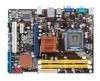
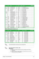
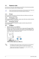
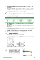
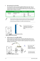
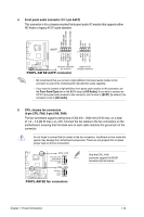
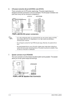
2. IDE connector (40-1 pin PRI_IDE) The onboard IDE connector is for the Ultra DMA 100/66/33 signal cable. There are three connectors on each Ultra DMA 100/66/33 signal cable: blue, black, and gray. Connect the blue connector to the motherboard's IDE connector, then select one of the following modes to configure your device. Driver Jumper setting Mode of device(s) Cable connector Single device Two devices Cable-Selected or Master Cable-Select Master Slave Master Slave Master Slave Black Black Gray Black or gray • Pin 20 on the IDE connector is removed to match the covered hole on the Ultra DMA cable connector. This prevents incorrect insertion when you connect the IDE cable. • Use the 80-conductor IDE cable for Ultra DMA 133/100/66 IDE devices. PRI_IDE If any device jumper is set as "Cable-Select," ensure that all other device jumpers have the same setting. PIN1 P5KPL-AM SE NOTE:Orient the red markings on the IDE ribbon cable to PIN 1. P5KPL-AM SE IDE connector 3. USB connectors (10-1 pin USB56, USB78) These connectors are for USB 2.0 ports. Connect the USB module cable to any of these connectors, then install the module to a slot opening at the back of the system chassis. These USB connectors comply with USB 2.0 specification that supports up to 480 Mbps connection speed. GND USB_P7+ USB_P7- USB+5V P5KPL-AM SE USB78 PIN 1 USB56 PIN 1 P5KPL-AM SE USB2.0 connectors USB+5V USB_P8- USB_P8+ GND NC USB+5V USB_P5USB_P5+ GND USB+5V USB_P6USB_P6+ GND NC Never connect a 1394 cable to the USB connectors. Doing so will damage the motherboard! The USB module cable is purchased separately. 1-11 ASUS P5KPL-AM SE
-
 1
1 -
2
-
3
-
4
-
5
-
6
-
7
-
8
-
9
-
10
-
11
-
12
-
13
-
14
-
 15
15 -
 16
16 -
 17
17 -
 18
18 -
 19
19 -
 20
20 -
 21
21 -
 22
22 -
 23
23 -
 24
24 -
 25
25 -
26
-
27
-
28
-
29
-
30
-
31
-
32
-
33
-
34
-
35
-
36
-
37
-
38
-
39
-
40
 |
 |