Asus P5LD2 SE Motherboard Installation Guide - Page 49
P5LD2 SE Internal Audio Connector, P5LD2 SE Analog Front Panel Connector
 |
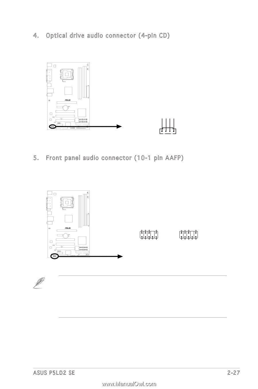
View all Asus P5LD2 SE manuals
Add to My Manuals
Save this manual to your list of manuals |
Page 49 highlights
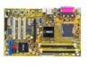
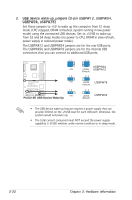
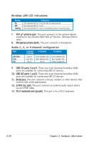
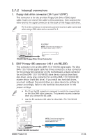
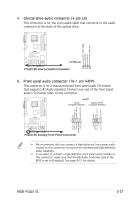
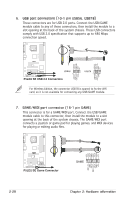
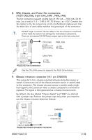
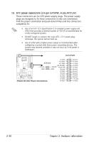
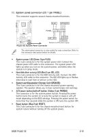
4. Optical drive audio connector (4-pin CD) This connector is for the 4-pin audio cable that connects to the audio connector at the back of the optical drive. P5LD2 SE Left Audio Channel Ground Ground Right Audio Channel Top:Line In Center:Line Out Below:Mic In R CD(Black) P5LD2 SE Internal Audio Connector 5. Front panel audio connector (10-1 pin AAFP) This connector is for a chassis-mounted front panel audio I/O module that supports HD Audio standard. Connect one end of the front panel audio I/O module cable to this connector. AAFP Azalia Legacy AC'97 compliant definition compliant definition P5LD2 SE Top:Line In Center:Line Out Below:Mic In R AGND +5VA BLINE_OUT_R BLINE_OUT_L GND PRESENCE# SENSE1_RETUR SENSE2_RETUR MIC2 MICPWR Line out_R NC Line out_L PORT1 L PORT1 R PORT2 R SENSE_SEND PORT2 L P5LD2 SE Analog Front Panel Connector • We recommend that you connect a high-definition front panel audio module to this connector to avail of the motherboard high-definition audio capability. • If you want to connect a high-definition front panel audio module to this connector, make sure that the HD Audio Controller item in the BIOS is set to [Enabled]. See page 4-27 for details. ASUS P5LD2 SE 2-27
-
 1
1 -
2
-
3
-
4
-
5
-
6
-
7
-
8
-
9
-
10
-
11
-
12
-
13
-
14
-
15
-
16
-
17
-
18
-
19
-
20
-
21
-
22
-
23
-
24
-
25
-
26
-
27
-
28
-
29
-
30
-
31
-
32
-
33
-
34
-
35
-
36
-
37
-
38
-
39
-
40
-
41
-
42
-
43
-
 44
44 -
 45
45 -
 46
46 -
 47
47 -
 48
48 -
 49
49 -
 50
50 -
 51
51 -
 52
52 -
 53
53 -
 54
54 -
55
-
56
-
57
-
58
-
59
-
60
-
61
-
62
-
63
-
64
-
65
-
66
-
67
-
68
-
69
-
70
-
71
-
72
-
73
-
74
-
75
-
76
-
77
-
78
-
79
-
80
-
81
-
82
-
83
-
84
-
85
-
86
-
87
-
88
-
89
-
90
-
91
-
92
-
93
-
94
-
95
-
96
-
97
-
98
-
99
-
100
-
101
-
102
-
103
-
104
-
105
-
106
-
107
-
108
-
109
-
110
-
111
-
112
-
113
-
114
-
115
-
116
-
117
-
118
-
119
-
120
 |
 |