Asus P5LD2-VM SE P5LD2-VM SE English Edition User's Manual
Asus P5LD2-VM SE Manual
 |
View all Asus P5LD2-VM SE manuals
Add to My Manuals
Save this manual to your list of manuals |
Asus P5LD2-VM SE manual content summary:
- Asus P5LD2-VM SE | P5LD2-VM SE English Edition User's Manual - Page 1
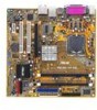
P5LD2-VM SE Motherboard - Asus P5LD2-VM SE | P5LD2-VM SE English Edition User's Manual - Page 2
Product warranty or service will not be extended if: (1) the product is repaired, modified or altered, unless such repair, modification of alteration is authorized in writing by ASUS; or (2) the serial number of the product is defaced or missing. ASUS PROVIDES THIS MANUAL "AS IS" WITHOUT WARRANTY - Asus P5LD2-VM SE | P5LD2-VM SE English Edition User's Manual - Page 3
vii About this guide viii Typography ix P5LD2-VM SE specifications summary x Chapter 1: Product introduction 1.1 Welcome 1-2 1.2 Package contents 1-2 1.3 Special features 1-2 1.3.1 Product highlights 1-2 1.3.2 Innovative ASUS features 1-5 1.4 Before you proceed 1-6 1.5 Motherboard overview - Asus P5LD2-VM SE | P5LD2-VM SE English Edition User's Manual - Page 4
ASUS CrashFree BIOS 2 utility 2-6 2.1.5 ASUS Update utility 2-8 2.2 BIOS setup program 2-11 2.2.1 BIOS menu screen 2-12 2.2.2 Menu bar 2-12 2.2.3 Navigation keys 2-12 2.2.4 Menu items 2-13 2.2.5 Sub-menu items 2-13 2.2.6 Configuration fields 2-13 2.2.7 Pop-up window 2.4.3 CPU Configuration - Asus P5LD2-VM SE | P5LD2-VM SE English Edition User's Manual - Page 5
2-35 2.6.3 Security 2-36 2.7 Exit menu 2-38 Chapter 3: Software support 3.1 Installing an operating system 3-2 3.2 Support CD information 3-2 3.2.1 Running the support CD 3-2 3.2.2 Drivers menu 3-3 3.2.3 Utilities menu 3-4 3.2.4 Manuals menu 3-5 3.2.5 ASUS Contact information 3-6 v - Asus P5LD2-VM SE | P5LD2-VM SE English Edition User's Manual - Page 6
if not installed and used in accordance with manufacturer's instructions, may cause harmful interference to radio communications. However, there The use of shielded cables for connection of the monitor to the graphics card is required to assure compliance with FCC regulations. Changes or - Asus P5LD2-VM SE | P5LD2-VM SE English Edition User's Manual - Page 7
Contact a qualified service technician or your retailer. Operation safety • Before installing the motherboard and adding devices on it, carefully read all the manuals that came with . • If you encounter technical problems with the product, contact a qualified service technician or your retailer. vii - Asus P5LD2-VM SE | P5LD2-VM SE English Edition User's Manual - Page 8
the BIOS parameters are also provided. • Chapter 3: Software support This chapter describes the contents of the support CD that comes with the motherboard package. Where to find more information Refer to the following sources for additional information and for product and software updates. 1. ASUS - Asus P5LD2-VM SE | P5LD2-VM SE English Edition User's Manual - Page 9
following symbols used throughout this manual. D A N G E R / W A R N I N G : Information to prevent injury to yourself when trying to complete a task. C A U T I O N : Information to prevent damage to the components when trying to complete a task. I M P O R T A N T : Instructions that you MUST follow - Asus P5LD2-VM SE | P5LD2-VM SE English Edition User's Manual - Page 10
P5LD2-VM SE specifications summary CPU Chipset Front Side Bus Memory VGA Expansion slots Storage Audio LAN USB Rear panel LGA775 socket for Intel® Core™2 Extreme/Core™2 Duo/ Pentium® D/Pentium® 4/Celeron® D processors Compatible with Intel® 05B/05A/06B processors Supports Intel® Enhanced Memory 64 - Asus P5LD2-VM SE | P5LD2-VM SE English Edition User's Manual - Page 11
P5LD2-VM SE specifications summary BIOS features 4 Mb Flash ROM, AMI BIOS, PnP, WfM2.0, DMI2.0, SM BIOS 2.3, ASUS EZ Flash, CrashFree BIOS2, C.P.R. (CPU Parameter Recall) Special features ASUS AI Overclocking ASUS EZ Flash ASUS CrashFree BIOS 2 ASUS MyLogo™ ASUS CPR (CPU Parameter Recall) I n d - Asus P5LD2-VM SE | P5LD2-VM SE English Edition User's Manual - Page 12
xii - Asus P5LD2-VM SE | P5LD2-VM SE English Edition User's Manual - Page 13
This chapter describes the motherboard features and the new technologies it supports. 1Product introduction ASUS P5LD2-VM SE 1-1 - Asus P5LD2-VM SE | P5LD2-VM SE English Edition User's Manual - Page 14
for the following items. Motherboard ASUS P5LD2-VM SE motherboard Cables 1 x Serial ATA signal cables 1 x Ultra DMA 133 cable 1 x Floppy disk drive cable Accessories I/O shield A p p l i c a t i o n C D s ASUS motherboard support CD D o c u m e n t a t i o n User guide If any of the above - Asus P5LD2-VM SE | P5LD2-VM SE English Edition User's Manual - Page 15
interface is software compatible with existing PCI specifications. See page 1-21 for details. 64-bit CPU support The motherboard supports 64-bit processors that provides high-performance computing and faster memory access required for memory and data intensive applications. ASUS P5LD2-VM SE 1-3 - Asus P5LD2-VM SE | P5LD2-VM SE English Edition User's Manual - Page 16
CPU and DRAM) to enhance system performance while still maintaining system stability. See section "2.4.1 JumperFree Configuration" to set the BIOS items for overclocking. Serial ATA technology The motherboard supports clear digital audio. S/PDIF digital sound ready The motherboard supports the S/PDIF - Asus P5LD2-VM SE | P5LD2-VM SE English Edition User's Manual - Page 17
due to overclocking, C.P.R. eliminates the need to open the system chassis and clear the RTC data. Simply shut down and reboot the system, and the BIOS automatically restores the CPU default setting for each parameter. ASUS P5LD2-VM SE 1-5 - Asus P5LD2-VM SE | P5LD2-VM SE English Edition User's Manual - Page 18
you should shut down the system and unplug the power cable before removing or plugging in any motherboard component. The illustration below shows the location of the onboard LED. ® P5LD2-VM SE SB_PWR P5LD2-VM SE Onboard LED ON Standby Power OFF Powered Off 1-6 Chapter 1: Product introduction - Asus P5LD2-VM SE | P5LD2-VM SE English Edition User's Manual - Page 19
in the image below. 1.5.2 Screw holes Place eight (8) screws into the holes indicated by circles to secure the motherboard to the chassis. Do not overtighten the screws! Doing so can damage the motherboard. Place this side towards the rear of the chassis ® P5LD2-VM SE ASUS P5LD2-VM SE 1-7 - Asus P5LD2-VM SE | P5LD2-VM SE English Edition User's Manual - Page 20
bit,240-pin module) ® P5LD2-VM SE DDR DIMM_A2 (64 bit,240-pin module) PARALLEL PORT VGA1 F_USB12 LAN_USB34 Top:Rear Speaker Out Center: Side Speaker Out Below: Center/Subwoofer Top:Line In Center:Line Out Below:Mic In CHA_FAN PCIEX16 Intel® GMCH 945G PRI_IDE Intel Gigabit LAN CD PCI1 SB_PWR - Asus P5LD2-VM SE | P5LD2-VM SE English Edition User's Manual - Page 21
removal of the PnP cap. 1.6.1 Installling the CPU To install a CPU: 1. Locate the CPU socket on the motherboard. ® P5LD2-VM SE P5LD2-VM SE CPU Socket 775 Before installing the CPU, make sure that the socket box is facing towards you and the load lever is on your left. ASUS P5LD2-VM SE 1-9 - Asus P5LD2-VM SE | P5LD2-VM SE English Edition User's Manual - Page 22
. 4. Lift the load plate with your thumb and forefinger to a 100º angle (A), then push the PnP cap from the load plate window to remove (B). B A Load plate 5. Position the CPU over the socket, making sure that the gold triangle is on the bottom-left corner of the socket. The socket alignment key - Asus P5LD2-VM SE | P5LD2-VM SE English Edition User's Manual - Page 23
! The motherboard supports Intel® Pentium® D or Intel® Pentium® 4 LGA775 processors with the Intel® Enhanced Memory 64 Technology (EM64T), Enhanced Intel SpeedStep® Technology (EIST), and Hyper-Threading Technology. Refer to the Appendix for more information on these CPU features. ASUS P5LD2-VM SE - Asus P5LD2-VM SE | P5LD2-VM SE English Edition User's Manual - Page 24
thermal condition and performance. • Install the motherboard to the chassis before you install the CPU fan and heatsink assembly • When you buy a boxed Intel® Pentium® 4 processor, the package includes the CPU fan and heatsink assembly. If you buy a CPU separately, make sure that you use only - Asus P5LD2-VM SE | P5LD2-VM SE English Edition User's Manual - Page 25
CPU fan cable to the connector on the motherboard labeled CPU_FAN. CPU_FAN CPU FAN PWM CPU FAN IN CPU FAN PWR GND ® P5LD2-VM SE P5LD2-VM SE CPU fan connector Do not forget to connect the CPU fan connector! Hardware monitoring errors can occur if you fail to plug this connector. ASUS P5LD2-VM SE - Asus P5LD2-VM SE | P5LD2-VM SE English Edition User's Manual - Page 26
1.6.3 Uninstalling the CPU heatsink and fan To uninstall the CPU heatsink and fan: 1. Disconnect the CPU fan cable from the connector on the motherboard. 2. Rotate each fastener counterclockwise. 3. Pull up two fasteners at a time in a diagonal sequence to disengage the heatsink B and fan - Asus P5LD2-VM SE | P5LD2-VM SE English Edition User's Manual - Page 27
4. Remove the heatsink and fan assembly from the motherboard. 5. Rotate each fastener clockwise to reset the orientation. The narrow end of the groove should point outward after resetting. (The photo shows the groove shaded for emphasis.) Narrow end of the groove ASUS P5LD2-VM SE 1-15 - Asus P5LD2-VM SE | P5LD2-VM SE English Edition User's Manual - Page 28
the location of the DDR2 DIMM sockets: ® P5LD2-VM SE DIMM_A2 DIMM_B2 P5LD2-VM SE 240-pin DDR2 DIMM sockets Channel Channel A Channel memory when you installed two 1 GB DDR2 memory modules. • This motherboard does not support memory modules made up of 128 Mb chips or double sided x16 memory - Asus P5LD2-VM SE | P5LD2-VM SE English Edition User's Manual - Page 29
S i d e ( s ) : S S - Single Sided D S - Double Sided DIMM Support: A - supports one module inserted into either slot, in a Single-channel memory configuration. B - supports on pair of modules inserted into the slots as one pair of Dual-channel memory configuration. ASUS P5LD2-VM SE 1-17 - Asus P5LD2-VM SE | P5LD2-VM SE English Edition User's Manual - Page 30
components. Failure to do so can cause severe damage to both the motherboard and the components. To install a DIMM: 1. Unlock a DIMM socket a socket to avoid damaging the DIMM. • The DDR2 DIMM sockets do not support DDR DIMMs. DO not install DDR DIMMs to the DDR2 DIMM sockets. 1.7.5 Removing - Asus P5LD2-VM SE | P5LD2-VM SE English Edition User's Manual - Page 31
cards that they support. Make sure unit cover (if your motherboard is already installed in BIOS settings, if any. See Chapter 2 for information on BIOS setup. 2. Assign an IRQ to the card. Refer to the tables on the next page. 3. Install the software drivers for the expansion card. ASUS P5LD2-VM SE - Asus P5LD2-VM SE | P5LD2-VM SE English Edition User's Manual - Page 32
motherboard PCI slot 1 PCI slot 2 PCI Express x16 slot PCI Express x1 slot Onboard USB controller 1 Onboard USB controller 2 Onboard USB controller 3 Onboard USB controller 4 Onboard USB 2.0 controller Onboard IDE port Onboard HD audio Onboard LAN , ensure that the drivers support "Share IRQ" or - Asus P5LD2-VM SE | P5LD2-VM SE English Edition User's Manual - Page 33
a graphics card installed on the PCI Express x16 slot. 1.8.6 PCI Express x1 This motherboard supports PCI Express x1 network cards, SCSI cards and other cards that comply with the PCI Express specifications. The figure shows a network card installed on the PCI Express x1 slot. ASUS P5LD2-VM SE - Asus P5LD2-VM SE | P5LD2-VM SE English Edition User's Manual - Page 34
! ® P5LD2-VM SE P5LD2-VM SE Clear RTC RAM CLRTC 12 23 Normal (Default) Clear CMOS You do not need to clear the RTC when the system hangs due to overclocking. For system failure due to overclocking, use the C.P.R. (CPU Parameter Recall) feature. Shut down and reboot the system so the BIOS can - Asus P5LD2-VM SE | P5LD2-VM SE English Edition User's Manual - Page 35
g h t b l u e ) . This port connects a tape, CD, DVD player, or other audio sources. 7 . L i n e O u t p o r t ( l i m e ) . This port connects a headphone or a speaker. In 4-channel, 6-channel, and 8-channel configuration, the function of this port becomes Front Speaker Out. ASUS P5LD2-VM SE 1-23 - Asus P5LD2-VM SE | P5LD2-VM SE English Edition User's Manual - Page 36
o r t ( g r a y ) . This port connects the center/ subwoofer speakers. Refer to the audio configuration table below for the function of the audio ports in 2, 4, 6, or 8-channel configuration. Audio 2, 4, 6, or 8-channel configuration Port Light Blue Lime Pink Orange Black Gray 2-channel (Headset - Asus P5LD2-VM SE | P5LD2-VM SE English Edition User's Manual - Page 37
-conductor IDE cable for Ultra DMA 100/66 IDE devices. PRI_IDE NOTE: Orient the red markings (usually zigzag) on the IDE ribbon cable to PIN 1. ® P5LD2-VM SE P5LD2-VM SE IDE connector PIN 1 ASUS P5LD2-VM SE 1-25 - Asus P5LD2-VM SE | P5LD2-VM SE English Edition User's Manual - Page 38
GND RSATA_TXP1 RSATA_TXN1 GND RSATA_RXP1 RSATA_RXN1 GND GND RSATA_TXP2 RSATA_TXN2 GND RSATA_RXP2 RSATA_RXN2 GND P5LD2-VM SE SATA connectors Install the Windows® 2000 Service Pack 4 or the Windows® XP Service Pack1 or later before using Serial ATA. 4. Speaker connector (4-pin SPEAKER) This 4-pin - Asus P5LD2-VM SE | P5LD2-VM SE English Edition User's Manual - Page 39
. Insufficient air flow inside the system may damage the motherboard components. These are not jumpers! DO NOT place jumper caps on the fan connectors. CPU_FAN CPU FAN PWM CPU FAN IN CPU FAN PWR GND ® P5LD2-VM SE P5LD2-VM SE Fan connectors CHA_FAN GND +12V Rotation ASUS P5LD2-VM SE 1-27 - Asus P5LD2-VM SE | P5LD2-VM SE English Edition User's Manual - Page 40
® P5LD2-VM SE +5V SPDIFOUT GND 6. Digital Audio connector (4-1 pin SPDIF_OUT) This connector is for the S/PDIF audio module to allow digital sound output. Connect one end of the S/PDIF audio cable to this connector and the other end to the S/PDIF module. SPDIF_OUT P5LD2-VM SE Digital audio - Asus P5LD2-VM SE | P5LD2-VM SE English Edition User's Manual - Page 41
SE ATX12V GND +12V DC +3 Volts +12 Volts +12 Volts +5V Standby Power OK GND +12V DC Ground +5 Volts Ground +5 Volts Ground P5LD2-VM SE ATX power connectors +3 Volts +3 Volts Ground +5 Volts +5 Volts +5 Volts -5 Volts Ground Ground Ground PSON# Ground -12 Volts +3 Volts ASUS P5LD2-VM SE - Asus P5LD2-VM SE | P5LD2-VM SE English Edition User's Manual - Page 42
chassis. These USB connectors comply with USB 2.0 specification that supports up to 480 Mbps connection speed. ® P5LD2-VM SE USB+5V USB_P8USB_P8+ GND NC USB+5V USB_P6USB_P6+ GND NC USB+5V USB_P7USB_P7+ GND USB56 1 P5LD2-VM SE USB 2.0 connectors USB+5V USB_P5USB_P5+ GND USB78 1 1-30 Chapter - Asus P5LD2-VM SE | P5LD2-VM SE English Edition User's Manual - Page 43
out_L PORT1 L PORT1 R PORT2 R SENSE_SEND PORT2 L P5LD2-VM SE Analog front panel connector It is recommended that you connect a high-definition front panel audio module to this connector to avail of the motherboard's high-definition audio capability. 12. Chassis intrusion connector (4-1 pin CHASSIS - Asus P5LD2-VM SE | P5LD2-VM SE English Edition User's Manual - Page 44
supports several chassis-mounted functions. ® P5LD2-VM SE F_PANEL PWRSW PWRLED GND PWR PWR_LEDPWR_LED+ Reset Ground IDE_LEDIDE_LED+ RESET IDE LED * Requires an ATX power supply. P5LD2-VM SE in SLEEP or SOFT-OFF mode depending on the BIOS settings. Pressing the power switch for more than four - Asus P5LD2-VM SE | P5LD2-VM SE English Edition User's Manual - Page 45
This chapter tells how to change the system settings through the BIOS Setup menus. Detailed descriptions of the BIOS parameters are also provided. 2 BIOS setup ASUS P5LD2-VM SE 2-1 - Asus P5LD2-VM SE | P5LD2-VM SE English Edition User's Manual - Page 46
using a floppy disk during POST.) 3. A S U S C r a s h F r e e B I O S 2 (Updates the BIOS using a bootable floppy disk or the motherboard support CD when the BIOS file fails or gets corrupted.) 4. A S U S U p d a t e (Updates the BIOS in Windows® environment.) Refer to the corresponding sections - Asus P5LD2-VM SE | P5LD2-VM SE English Edition User's Manual - Page 47
the ASUS website (www.asus.com) to download the latest BIOS file for the motherboard and rename the same to P 5 L D 2 V M S . R O M. 2. Save the BIOS file to a floppy disk, then restart the system. 3. Press + during POST to display the following. EZFlash starting BIOS update Checking - Asus P5LD2-VM SE | P5LD2-VM SE English Edition User's Manual - Page 48
-protected and has at least 600 KB free space to save the file. • The succeeding BIOS screens are for reference only. The actual BIOS screen displays may not be exactly the same as shown. 1. Copy the AFUDOS utility (afudos.exe) from the motherboard support CD to the bootable floppy disk you created - Asus P5LD2-VM SE | P5LD2-VM SE English Edition User's Manual - Page 49
from the hard disk drive. A:\>afudos /iP5LD2VMS.ROM AMI Firmware Update Utility - Version 1.10 Copyright (C) 2002 American Megatrends, Inc. All rights reserved. Reading file ..... done Erasing flash .... done Writing flash .... 0x0008CC00 (9%) Verifying flash .. done A:\> ASUS P5LD2-VM SE 2-5 - Asus P5LD2-VM SE | P5LD2-VM SE English Edition User's Manual - Page 50
2 utility The ASUS CrashFree BIOS 2 is an auto recovery tool that allows you to restore the BIOS file when it fails or gets corrupted during the updating process. You can update a corrupted BIOS file using the motherboard support CD or the floppy disk that contains the updated BIOS file. • Prepare - Asus P5LD2-VM SE | P5LD2-VM SE English Edition User's Manual - Page 51
updating the BIOS! Doing so can cause system boot failure! 4. Restart the system after the utility completes the updating process. The recovered BIOS may not be the latest BIOS version for this motherboard. Visit the ASUS website (www.asus.com) to download the latest BIOS file. ASUS P5LD2-VM SE - Asus P5LD2-VM SE | P5LD2-VM SE English Edition User's Manual - Page 52
you to manage, save, and update the motherboard BIOS in Windows® environment. The ASUS Update utility allows you to: • Save the current BIOS file • Download the latest BIOS file from the Internet • Update the BIOS from an updated BIOS file • Update the BIOS directly from the Internet, and • View - Asus P5LD2-VM SE | P5LD2-VM SE English Edition User's Manual - Page 53
d a t e. The ASUS Update main window appears. 2. Select U p d a t e B I O S f r o m 3. Select the ASUS FTP site t h e I n t e r n e t option from the nearest you to avoid network drop-down menu, then click traffic, or click A u t o S e l e c t. N e x t. Click N e x t. ASUS P5LD2-VM SE 2-9 - Asus P5LD2-VM SE | P5LD2-VM SE English Edition User's Manual - Page 54
to download. Click Next. 5. Follow the screen instructions to complete the update process. The ASUS Update utility is capable of updating itself through the Internet. Always update the utility to avail all its features. Updating the BIOS through a BIOS file To update the BIOS through a BIOS file - Asus P5LD2-VM SE | P5LD2-VM SE English Edition User's Manual - Page 55
Exit Menu. See section "2.7 Exit Menu." • The BIOS setup screens shown in this section are for reference purposes only, and may not exactly match what you see on your screen. • Visit the ASUS website (www.asus.com) to download the latest BIOS file for this motherboard and . ASUS P5LD2-VM SE 2-11 - Asus P5LD2-VM SE | P5LD2-VM SE English Edition User's Manual - Page 56
2.2.1 BIOS menu screen Menu items Menu bar Configuration fields General help System Time System Date Legacy Diskette A Primary IDE Master Primary IDE Slave select items in the menu and change the settings. Some of the navigation keys differ from one screen to another. 2-12 Chapter 2: BIOS setup - Asus P5LD2-VM SE | P5LD2-VM SE English Edition User's Manual - Page 57
] [Auto] Graphic Adapter Priority Graphics Aperture Size Spread Spectrum [AGP/PCI] [ 64 MB] [Enabled] ICH Delayed Transaction [Enabled] MPS Revision [1.4] Select Screen Select Item +- Change Option F1 General Help F10 Save and Exit ESC Exit Pop-up window Scroll bar ASUS P5LD2-VM SE 2-13 - Asus P5LD2-VM SE | P5LD2-VM SE English Edition User's Manual - Page 58
screen appears, giving you an overview of the basic system information. Refer to section "2.2.1 BIOS menu screen" for information on the menu screen items and how to navigate through them. , 5.25 in.] [1.2M , 5.25 in.] [720K , 3.5 in.] [1.44M, 3.5 in.] [2.88M, 3.5 in.] 2-14 Chapter 2: BIOS setup - Asus P5LD2-VM SE | P5LD2-VM SE English Edition User's Manual - Page 59
Fourth IDE Master/Slave While entering Setup, the BIOS automatically detects the presence of IDE devices. supports multi-sector transfer feature. When set to [Disabled], the data transfer from and to the device occurs one sector at a time. Configuration options: [Disabled] [Auto] ASUS P5LD2-VM SE - Asus P5LD2-VM SE | P5LD2-VM SE English Edition User's Manual - Page 60
to configure the item. IDE Configuration Configure SATA As Onboard IDE Operate Mode Enhanced Mode Support On IDE Detect Time Out (Sec) [Standard IDE] [Enhanced Mode] [S-ATA] [35 native OS, such as Windows® 2000/XP. Configuration options: [Disabled] [Compatible Mode] [Enhanced Mode] 2- - Asus P5LD2-VM SE | P5LD2-VM SE English Edition User's Manual - Page 61
Enhanced Mode Support On [S-ATA] problems, revert to the default setting S - A T A. Configuration options: [P-ATA+S-ATA] [S-ATA] [P-ATA] IDE Detect Time Out [35] Selects the time out value for detecting ATA/ATAPI devices. Configuration options: [0] [5] [10] [15] [20] [25] [30] [35] ASUS P5LD2-VM SE - Asus P5LD2-VM SE | P5LD2-VM SE English Edition User's Manual - Page 62
gives you an overview of the general system specifications. The BIOS automatically detects the items in this menu. AMIBIOS Version : 0128 Build Date : 05/11/05 Processor Type Speed Count : Genuine Intel(R) CPU 3.20GHz : 3200 MHz : 1 System Memory Size : 512MB Appropriated : 0MB Available - Asus P5LD2-VM SE | P5LD2-VM SE English Edition User's Manual - Page 63
JumperFree Configuration USB Configuration CPU Configuration Chipset Onboard Devices Configuration PCI PnP Configure CPU. Select Screen Select the system. O v e r c l o c k P r o f i l e - loads overclocking profiles with optimal parameters for stability when overclocking. ASUS P5LD2-VM SE 2-19 - Asus P5LD2-VM SE | P5LD2-VM SE English Edition User's Manual - Page 64
when you set the A I O v e r c l o c k i n g item to [Manual]. CPU Frequency [XXX] Displays the frequency sent by the clock generator to the system bus and PCI bus. The value of this item is auto-detected by the BIOS. Use the < + > and < - > keys to adjust the CPU frequency. You can also type the - Asus P5LD2-VM SE | P5LD2-VM SE English Edition User's Manual - Page 65
A I O v e r c l o c k i n g item is set to [Overclock Profile]. Overclock Options [Overclock 5%] Allows you to overclock the CPU speed through the available preset values. Configuration options: [Overclock 5%] [Overclock 10%] [Overclock 15%] [Overclock 20%] [Overclock 30%] ASUS P5LD2-VM SE 2-21 - Asus P5LD2-VM SE | P5LD2-VM SE English Edition User's Manual - Page 66
Support USB 2.0 Controller USB 2.0 Controller Mode BIOS EHCI Legacy USB Support [Auto] Allows you to enable or disable support for USB is detected, the legacy USB support is disabled. Configuration options: [Disabled Speed] BIOS EHCI Hand-off [Disabled] Allows you to enable support for operating - Asus P5LD2-VM SE | P5LD2-VM SE English Edition User's Manual - Page 67
you to enable or disable the microcode updation. Configuration options: [Disabled] [Enabled] Max CPUID Value Limit [Disabled] Enable this item to boot legacy operating systems that cannot support CPUs with extended CPUID functions. Configuration options: [Disabled] [Enabled] ASUS P5LD2-VM SE 2-23 - Asus P5LD2-VM SE | P5LD2-VM SE English Edition User's Manual - Page 68
only when you install a processor with the Execute Disable function. Configuration options: [Disabled] [Enabled] Enhanced C1 Control [Auto] When set to [Auto], the BIOS will automatically check the CPU's capability to enable the C1E support. In C1E mode, the CPU power consumption is lower when - Asus P5LD2-VM SE | P5LD2-VM SE English Edition User's Manual - Page 69
Graphics memory type [Auto] Advanced Chipset Settings Configure DRAM Timing by SPD [Enabled] When this item is enabled, the DRAM timing parameters are set according to the DRAM SPD (Serial Presence Detect). When disabled, you can manually ] [4 Clocks] [5 Clocks] [6 Clocks] ASUS P5LD2-VM SE 2-25 - Asus P5LD2-VM SE | P5LD2-VM SE English Edition User's Manual - Page 70
] [Enabled, 1MB] [Enabled, 8MB] Graphics memory type [Auto] Sets the graphics memory type. Configuration options: [Auto] [DVMT] [FIX] [DVMT+FIX] 2.4.5 Onboard Devices Configuration Configure Win627EHF Super IO Chipset HD Audio Controller Onboard PCIEX GbE LAN LAN Option ROM [Enabled] [Enabled - Asus P5LD2-VM SE | P5LD2-VM SE English Edition User's Manual - Page 71
of the Parallel Port EPP version. This item appears only when the P a r a l l e l P o r t M o d e is set to E P P. Configuration options: [1.9] [1.7] Parallel Port IRQ [IRQ7] Configuration options: [IRQ5] [IRQ7] ASUS P5LD2-VM SE 2-27 - Asus P5LD2-VM SE | P5LD2-VM SE English Edition User's Manual - Page 72
for an IRQ. When set to [No], BIOS does not assign an IRQ to the PCI VGA card even if requested. Configuration options: [No] [Yes] Palette Snooping [Disabled] When set to [Enabled], the pallete snooping feature informs the PCI devices that an ISA graphics device is installed in the system so that - Asus P5LD2-VM SE | P5LD2-VM SE English Edition User's Manual - Page 73
you to enable or disable the Advanced Configuration and Power Interface (ACPI) support in the Application-Specific Integrated Circuit (ASIC). When set to Enabled, the ACPI APIC table pointer is included in the RSDT pointer list. Configuration options: [Disabled] [Enabled] ASUS P5LD2-VM SE 2-29 - Asus P5LD2-VM SE | P5LD2-VM SE English Edition User's Manual - Page 74
an external modem off and then back on while the computer is off causes an initialization string that turns the system power on. 2-30 Chapter 2: BIOS setup - Asus P5LD2-VM SE | P5LD2-VM SE English Edition User's Manual - Page 75
], this parameter allows you to turn on the system through a PCI LAN or modem card. This feature requires an ATX power supply that provides LAN card. This feature requires an ATX power supply that provides at least 1A on the +5VSB lead. Configuration options: [Disabled] [Enabled] ASUS P5LD2-VM SE - Asus P5LD2-VM SE | P5LD2-VM SE English Edition User's Manual - Page 76
CPU Temperature [xxxC/xxxF] MB Temperature [xxxC/xxxF] The onboard hardware monitor automatically detects and displays the motherboard and CPU motherboard, the field shows N/A. Configuration options: [Ignored] [xxxRPM] CPU Q-Fan Control [Disabled] Allows you to enable or disable the ASUS - Asus P5LD2-VM SE | P5LD2-VM SE English Edition User's Manual - Page 77
: [Ignored] [xxxRPM] or [N/A] VCORE Voltage, 3.3V Voltage, 5V Voltage, 12V Voltage The onboard hardware monitor automatically detects the voltage output through the onboard voltage regulators. ASUS P5LD2-VM SE 2-33 - Asus P5LD2-VM SE | P5LD2-VM SE English Edition User's Manual - Page 78
Priority 1st Boot Device 2nd Boot Device 3rd Boot Device [1st FLOPPY DRIVE] [PM-ST330620A] [PS-ASUS CD-S360] 1st ~ xxth Boot Device [1st Floppy Drive] These items specify the boot device priority sequence in the system. Configuration options: [xxxxx Drive] [Disabled] 2-34 Chapter 2: BIOS setup - Asus P5LD2-VM SE | P5LD2-VM SE English Edition User's Manual - Page 79
PS/2 Mouse Support Wait For 'F1' If Error Hit 'DEL' Message Display Interrupt 19 Capture [Enabled] [Enabled] [Force BIOS] [On] [Auto] [Enabled] [Enabled] [Disabled] Allows BIOS to skip certain Press DEL to run Setup" during POST. Configuration options: [Disabled] [Enabled] ASUS P5LD2-VM SE 2-35 - Asus P5LD2-VM SE | P5LD2-VM SE English Edition User's Manual - Page 80
password. To clear the supervisor password, select the Change Supervisor Password then press . The message "Password Uninstalled" appears. If you forget your BIOS password, you can clear clear it by erasing the CMOS Real Time Clock (RTC) RAM. See section "2.6 Jumpers" for information on how - Asus P5LD2-VM SE | P5LD2-VM SE English Edition User's Manual - Page 81
. To change the user password, follow the same steps as in setting a user password. Clear User Password Select this item to clear the user password. ASUS P5LD2-VM SE 2-37 - Asus P5LD2-VM SE | P5LD2-VM SE English Edition User's Manual - Page 82
the optimal or failsafe default values for the BIOS items, and save or discard your changes to the BIOS items. Exit Options Exit & Save Changes Exit even when the PC is turned off. When you select this option, a confirmation window appears. Select O k to save changes and exit. If you attempt to exit - Asus P5LD2-VM SE | P5LD2-VM SE English Edition User's Manual - Page 83
other than System Date, System Time, and Password, the BIOS asks for a confirmation before exiting. Discard Changes This window appears. Select O k to load default values. Select E x i t & S a v e C h a n g e s or make other changes before saving the values to the non-volatile RAM. ASUS P5LD2-VM SE - Asus P5LD2-VM SE | P5LD2-VM SE English Edition User's Manual - Page 84
2-40 Chapter 2: BIOS setup - Asus P5LD2-VM SE | P5LD2-VM SE English Edition User's Manual - Page 85
This chapter describes the contents of the support CD that comes with the motherboard package. 3 Software support ASUS P5LD2-VM SE 3-1 - Asus P5LD2-VM SE | P5LD2-VM SE English Edition User's Manual - Page 86
that you install Windows® 2000 Service Pack 4 or the Windows® XP Service Pack 1 or later versions before installing the drivers for better compatibility and system stability. 3.2 Support CD information The support CD that came with the motherboard package contains the drivers, software applications - Asus P5LD2-VM SE | P5LD2-VM SE English Edition User's Manual - Page 87
utility for details. Intel(R) Graphics Accelerator Driver Installs the Intel® Graphics Accelerator driver. Realtek Audio Driver Installs the Realtek® ALC882 high-definition audio driver and application. Intel(R) Tekoa Ethernet Driver Installs the Intel® Tekoa Ethernet driver. ASUS P5LD2-VM SE 3-3 - Asus P5LD2-VM SE | P5LD2-VM SE English Edition User's Manual - Page 88
detected problems. This utility helps you keep your computer in healthy operating condition. ASUS Update The ASUS Update utility allows you to update the motherboard BIOS in a Windows® environment. This utility requires an Internet connection either through a network or an Internet Service Provider - Asus P5LD2-VM SE | P5LD2-VM SE English Edition User's Manual - Page 89
Manuals menu contains a list of supplementary user manuals. Click an item to open the folder of the user manual. Most user manual files are in Portable Document Format (PDF). Install the Adobe® Acrobat® Reader from the U t i l i t i e s m e n u before opening a user manual file. ASUS P5LD2-VM SE - Asus P5LD2-VM SE | P5LD2-VM SE English Edition User's Manual - Page 90
3.2.5 ASUS Contact information Click the C o n t a c t tab to display the ASUS contact information. You can also find this information on the inside front cover of this user guide. 3-6 Chapter 3: Software support
-
 1
1 -
 2
2 -
 3
3 -
 4
4 -
 5
5 -
 6
6 -
 7
7 -
8
-
9
-
10
-
11
-
12
-
13
-
14
-
15
-
16
-
17
-
18
-
19
-
20
-
21
-
22
-
23
-
24
-
25
-
26
-
27
-
28
-
29
-
30
-
31
-
32
-
33
-
34
-
35
-
36
-
37
-
38
-
39
-
40
-
41
-
42
-
43
-
44
-
45
-
46
-
47
-
48
-
49
-
50
-
51
-
52
-
53
-
54
-
55
-
56
-
57
-
58
-
59
-
60
-
61
-
62
-
63
-
64
-
65
-
66
-
67
-
68
-
69
-
70
-
71
-
72
-
73
-
74
-
75
-
76
-
77
-
78
-
79
-
80
-
81
-
82
-
83
-
84
-
85
-
86
-
87
-
88
-
89
-
90
 |
 |

Motherboard
P5LD2-VM SE