Asus P5LD2-VM P5LD2-VM User's Manual for English Edition
Asus P5LD2-VM Manual
 |
View all Asus P5LD2-VM manuals
Add to My Manuals
Save this manual to your list of manuals |
Asus P5LD2-VM manual content summary:
- Asus P5LD2-VM | P5LD2-VM User's Manual for English Edition - Page 1
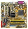
P5LD2-VM Motherboard - Asus P5LD2-VM | P5LD2-VM User's Manual for English Edition - Page 2
express written permission of ASUSTeK COMPUTER INC. ("ASUS"). Product warranty or service will not be extended if: (1) the ASUS HAS BEEN ADVISED OF THE POSSIBILITY OF SUCH DAMAGES ARISING FROM ANY DEFECT OR ERROR IN THIS MANUAL OR PRODUCT. SPECIFICATIONS AND INFORMATION CONTAINED IN THIS MANUAL - Asus P5LD2-VM | P5LD2-VM User's Manual for English Edition - Page 3
vii About this guide viii Typography ix P5LD2-VM specifications summary x Chapter 1: Product introduction 1.1 Welcome 1-2 1.2 Package contents 1-2 1.3 Special features 1-2 1.3.1 Product highlights 1-2 1.3.2 Innovative ASUS features 1-4 1.4 Before you proceed 1-5 1.5 Motherboard overview - Asus P5LD2-VM | P5LD2-VM User's Manual for English Edition - Page 4
1-24 Chapter 2: BIOS setup 2.1 Managing and updating your BIOS 2-2 2.1.1 Creating a bootable floppy disk 2-2 2.1.2 ASUS EZ Flash utility 2-3 2.1.3 AFUDOS utility 2-4 2.1.4 ASUS CrashFree BIOS 2 utility 2-6 2.1.5 ASUS Update utility 2-8 2.2 BIOS setup program 2-11 2.2.1 BIOS menu screen 2-12 - Asus P5LD2-VM | P5LD2-VM User's Manual for English Edition - Page 5
Exit menu 2-38 Chapter 3: Software support 3.1 Installing an operating system 3-2 3.2 Support CD information 3-2 3.2.1 Running the support CD 3-2 3.2.2 Drivers menu 3-3 3.2.3 Utilities menu 3-4 3.2.4 Manuals menu 3-5 3.2.5 ASUS Contact information 3-6 Appendix: CPU features A.1 Intel® EM64T - Asus P5LD2-VM | P5LD2-VM User's Manual for English Edition - Page 6
and used in accordance with manufacturer's instructions, may cause harmful interference to radio by turning the equipment off and on, the user is encouraged to try to correct the interference by for connection of the monitor to the graphics card is required to assure compliance with FCC regulations - Asus P5LD2-VM | P5LD2-VM User's Manual for English Edition - Page 7
Contact a qualified service technician or your retailer. Operation safety • Before installing the motherboard and adding devices on it, carefully read all the manuals that came with . • If you encounter technical problems with the product, contact a qualified service technician or your retailer. vii - Asus P5LD2-VM | P5LD2-VM User's Manual for English Edition - Page 8
guide This user guide contains the information you need when installing and configuring the motherboard. How this guide is organized This manual contains the following parts: • Chapter 1: Product introduction This chapter describes the features of the motherboard and the new technology it supports - Asus P5LD2-VM | P5LD2-VM User's Manual for English Edition - Page 9
following symbols used throughout this manual. D A N G E R / W A R N I N G : Information to prevent injury to yourself when trying to complete a task. C A U T I O N : Information to prevent damage to the components when trying to complete a task. I M P O R T A N T : Instructions that you MUST follow - Asus P5LD2-VM | P5LD2-VM User's Manual for English Edition - Page 10
P5LD2-VM specifications summary CPU Chipset Front Side Bus Memory VGA Expansion slots Storage Audio LAN USB Rear panel LGA775 socket for Intel® Pentium® D/Intel® Pentium® 4 or Intel® Celeron® processors Compatible with Intel® PCG 05B/05A and 04B/04A processors Supports Intel® Enhanced Memory 64 - Asus P5LD2-VM | P5LD2-VM User's Manual for English Edition - Page 11
P5LD2-VM specifications summary BIOS features 4 Mb Flash ROM, AMI BIOS, PnP, WfM2.0, DMI2.0, SM BIOS 2.3, ASUS EZ Flash, CrashFree BIOS2, C.P.R. (CPU Parameter Recall) Special features ASUS AI Overclocking ASUS EZ Flash ASUS CrashFree BIOS 2 ASUS MyLogo2™ ASUS CPR (CPU Parameter Recall) I n d u - Asus P5LD2-VM | P5LD2-VM User's Manual for English Edition - Page 12
xii - Asus P5LD2-VM | P5LD2-VM User's Manual for English Edition - Page 13
This chapter describes the motherboard features and the new technologies it supports. 1Product introduction ASUS P5LD2-VM 1-1 - Asus P5LD2-VM | P5LD2-VM User's Manual for English Edition - Page 14
for the following items. Motherboard ASUS P5LD2-VM motherboard Cables 2 x Serial ATA signal cables 1 x Ultra DMA 133 cable 1 x Floppy disk drive cable Accessories I/O shield A p p l i c a t i o n C D s ASUS motherboard support CD D o c u m e n t a t i o n User guide If any of the above - Asus P5LD2-VM | P5LD2-VM User's Manual for English Edition - Page 15
technology The motherboard supports the Serial ATA technology through the Serial ATA interfaces and the Intel® ICH7 chipset. The SATA specification allows for thinner, more flexible cables with lower pin count, reduced voltage requirement, and up to 300 MB/s data transfer rate. ASUS P5LD2-VM 1-3 - Asus P5LD2-VM | P5LD2-VM User's Manual for English Edition - Page 16
to buy a replacement ROM chip. See details on page 2-6. ASUS MyLogo2™ This new feature present in the motherboard allows you to personalize and add style to your system with customizable boot logos. See page 2-35. ASUS EZ Flash BIOS With the ASUS EZ Flash, you can easily update the system BIOS even - Asus P5LD2-VM | P5LD2-VM User's Manual for English Edition - Page 17
This is a reminder that you should shut down the system and unplug the power cable before removing or plugging in any motherboard component. The illustration below shows the location of the onboard LED. ® P5LD2-VM P5LD2-VM Onboard LED SB_PWR ON Standby Power OFF Powered Off ASUS P5LD2-VM 1-5 - Asus P5LD2-VM | P5LD2-VM User's Manual for English Edition - Page 18
image below. 1.5.2 Screw holes Place eight (8) screws into the holes indicated by circles to secure the motherboard to the chassis. Do not overtighten the screws! Doing so can damage the motherboard. Place this side towards the rear of the chassis ® P5LD2-VM 1-6 Chapter 1: Product introduction - Asus P5LD2-VM | P5LD2-VM User's Manual for English Edition - Page 19
:Mic In CHA_FAN PCIEX16 Intel® GMCH 945G PRI_IDE Intel 82573V CD PCI1 SB_PWR PCI2 PCIEX1_1 CR2032 3V Lithium Cell CMOS Power AAFP SPDIF_OUT USB56 Intel® ICH7 Intel FWH 4Mb SATA3 SATA4 CLRTC SATA1 SATA2 BUZZ USB78 PCI_EIDE PLED CHASSIS SPEAKER ITE 8211 F_PANEL ASUS P5LD2-VM 1-7 - Asus P5LD2-VM | P5LD2-VM User's Manual for English Edition - Page 20
/removal, or misplacement/ loss/incorrect removal of the PnP cap. 1.6.1 Installling the CPU To install a CPU: 1. Locate the CPU socket on the motherboard. ® P5LD2-VM P5LD2-VM CPU Socket 775 Before installing the CPU, make sure that the socket box is facing towards you and the load lever - Asus P5LD2-VM | P5LD2-VM User's Manual for English Edition - Page 21
cap B from the load plate window to remove (B). Load plate 5. Position the CPU over the socket, making sure that the gold triangle is on the bottom-left corner of the socket. The socket alignment key should fit A l i g n m e n t k e y into the CPU notch. Gold triangle mark ASUS P5LD2-VM A 1-9 - Asus P5LD2-VM | P5LD2-VM User's Manual for English Edition - Page 22
the socket to prevent bending the connectors on the socket and damaging the CPU! The motherboard supports Intel® Pentium® D or Intel® Pentium® 4 LGA775 processors with the Intel® Enhanced Memory 64 Technology (EM64T), Enhanced Intel SpeedStep® Technology (EIST), and Hyper-Threading Technology. Refer - Asus P5LD2-VM | P5LD2-VM User's Manual for English Edition - Page 23
. To install the CPU heatsink and fan: 1. Place the heatsink on top of the installed CPU, making sure that the four fasteners match the holes on the motherboard. Fastener Motherboard hole Make sure each fastener is oriented as shown, with the narrow groove directed outward. ASUS P5LD2-VM 1-11 - Asus P5LD2-VM | P5LD2-VM User's Manual for English Edition - Page 24
the fan and heatsink assembly is in place, connect the CPU fan cable to the connector on the motherboard labeled CPU_FAN. CPU_FAN CPU FAN PWM CPU FAN IN CPU FAN PWR GND ® P5LD2-VM P5LD2-VM CPU fan connector Do not forget to connect the CPU fan connector! Hardware monitoring errors can occur if you - Asus P5LD2-VM | P5LD2-VM User's Manual for English Edition - Page 25
and fan: 1. Disconnect the CPU fan cable from the connector on the motherboard. 2. Rotate each fastener counterclockwise. 3. Pull up two fasteners at a time in a diagonal sequence to disengage the heatsink B and fan assembly from the A A motherboard. B A B B A ASUS P5LD2-VM 1-13 - Asus P5LD2-VM | P5LD2-VM User's Manual for English Edition - Page 26
4. Remove the heatsink and fan assembly from the motherboard. 5. Rotate each fastener clockwise to reset the orientation. The narrow end of the groove should point outward after resetting. (The photo shows the groove shaded - Asus P5LD2-VM | P5LD2-VM User's Manual for English Edition - Page 27
List on the next page for details. • Due to chipset resource allocation, the system may detect less than 4 GB system memory when you installed four 1 GB DDR2 memory modules. • This motherboard does not support memory modules made up of 128 Mb chips or double sided x16 memory modules. ASUS P5LD2-VM - Asus P5LD2-VM | P5LD2-VM User's Manual for English Edition - Page 28
1.7.3 DDR2 Qualified Vendors List The following table lists the memory modules that have been tested and qualified for use with this motherboard. Visit the ASUS website (www.asus.com) for the latest DDR2 DIMM modules for this motherboard. DDR2 533 Qualified Vendors List Size Vendor 512MB 256MB - Asus P5LD2-VM | P5LD2-VM User's Manual for English Edition - Page 29
cause severe damage to both the motherboard and the components. To install a Support the DIMM lightly with your fingers when pressing the retaining clips. The DIMM might get damaged when it flips out with extra force. 1 2 1 DDR2 DIMM notch 2. Remove the DIMM from the socket. ASUS P5LD2-VM - Asus P5LD2-VM | P5LD2-VM User's Manual for English Edition - Page 30
slots and the expansion cards that they support. Make sure to unplug the power cord before adding or removing expansion cards. Failure to do so may cause you physical injury and damage motherboard components. 1.8.1 Installing an expansion card To install an expansion card: 1. Before installing the - Asus P5LD2-VM | P5LD2-VM User's Manual for English Edition - Page 31
shared - - - - - shared - - - - - - When using PCI cards on shared slots, ensure that the drivers support "Share IRQ" or that the cards do not need IRQ assignments. Otherwise, conflicts will arise between the two PCI groups, making the system unstable and the card inoperable. ASUS P5LD2-VM 1-19 - Asus P5LD2-VM | P5LD2-VM User's Manual for English Edition - Page 32
PCI slots The PCI slots support cards such as a LAN card, SCSI card, USB card, and other cards that comply with PCI specifications. The figure shows a LAN card installed on a PCI slot. 1.8.5 PCI Express x16 This motherboard supports one PCI Express x16 graphics card. The figure shows a graphics - Asus P5LD2-VM | P5LD2-VM User's Manual for English Edition - Page 33
battery. 5. Plug the power cord and turn ON the computer. 6. Hold down the key during the boot process and enter BIOS setup to re-enter data. Except when clearing the RTC RAM, never remove the cap on CLRTC jumper default position. Removing the cap will cause system boot failure! ® P5LD2-VM - Asus P5LD2-VM | P5LD2-VM User's Manual for English Edition - Page 34
1 Gbps connection ACT/LINK SPEED LED LED LAN port 4 . R e a r S p e a k e r O u t p o r t ( o r a n g e ) . This port connects the rear speakers on a 4-channel, 6-channel, or 8-channel audio configuration. 5 . S i d e S p e a k e r O u t p o r t ( b l a c k ) . This port connects the side - Asus P5LD2-VM | P5LD2-VM User's Manual for English Edition - Page 35
to the audio configuration table below for the function of the audio ports in 2, 4, 6, or 8-channel configuration. Audio 2, 4, o n n e c t o r . This 9-pin COM1 port is for serial devices. 1 4 . P S / 2 k e y b o a r d p o r t ( p u r p l e ) . This port is for a PS/2 keyboard. ASUS P5LD2-VM 1-23 - Asus P5LD2-VM | P5LD2-VM User's Manual for English Edition - Page 36
to PIN 1. PIN 1 P5LD2-VM Floppy disk drive connector 2 . Primary IDE connector (40-1 pin PRI_IDE) These connectors are for Ultra DMA 100/66 signal cables. The Ultra DMA 100/66 signal cable has three connectors: a blue connector for the primary IDE connector on the motherboard, a black connector for - Asus P5LD2-VM | P5LD2-VM User's Manual for English Edition - Page 37
® P5LD2-VM SATA3 SATA1 SATA4 SATA2 GND RSATA_TXP1 RSATA_TXN1 GND RSATA_RXP1 RSATA_RXN1 GND GND RSATA_TXP2 RSATA_TXN2 GND RSATA_RXP2 RSATA_RXN2 GND P5LD2-VM SATA connectors Install the Windows® 2000 Service Pack 4 or the Windows® XP Service Pack1 or later before using Serial ATA. ASUS P5LD2-VM - Asus P5LD2-VM | P5LD2-VM User's Manual for English Edition - Page 38
allows you to hear system beeps and warnings. ® P5LD2-VM P5LD2-VM Speaker out connector SPEAKER +5V GND GND Speak Out 1 6 . CPU, Power and Chassis fan connectors (4-pin CPU_FAN, 3-pin PWR_RAN, 3-pin CHA_FAN) The fan connectors support cooling fans of 350mA~740mA (8.88W max.) or a total of 1A - Asus P5LD2-VM | P5LD2-VM User's Manual for English Edition - Page 39
output. Connect one end of the S/PDIF audio cable to this connector and the other end to the S/PDIF module. SPDIF_OUT P5LD2-VM Digital audio connector The S/PDIF out module is purchased separately system is in sleep mode. ® P5LD2-VM P5LD2-VM PLED connector PLED PLEDNC PLED+ 1 ASUS P5LD2-VM 1-27 - Asus P5LD2-VM | P5LD2-VM User's Manual for English Edition - Page 40
ATX12V GND +12V DC +3 Volts +12 Volts +12 Volts +5V Standby Power OK GND +12V DC Ground +5 Volts Ground +5 Volts Ground P5LD2-VM ATX power connectors +3 Volts +3 Volts Ground +5 Volts +5 Volts +5 Volts -5 Volts Ground Ground Ground PSON# Ground -12 Volts +3 Volts 1-28 Chapter 1: Product - Asus P5LD2-VM | P5LD2-VM User's Manual for English Edition - Page 41
chassis. These USB connectors comply with USB 2.0 specification that supports up to 480 Mbps connection speed. ® P5LD2-VM USB+5V USB_P8USB_P8+ GND NC USB+5V USB_P6USB_P6+ GND NC USB+5V USB_P7USB_P7+ GND USB56 1 P5LD2-VM USB 2.0 connectors USB+5V USB_P5USB_P5+ GND USB78 1 ASUS P5LD2-VM 1-29 - Asus P5LD2-VM | P5LD2-VM User's Manual for English Edition - Page 42
out_L PORT1 L PORT1 R PORT2 R SENSE_SEND PORT2 L P5LD2-VM Analog front panel connector It is recommended that you connect a high-definition front panel audio module to this connector to avail of the motherboard's high-definition audio capability. 13. Chassis intrusion connector (4-1 pin CHASSIS - Asus P5LD2-VM | P5LD2-VM User's Manual for English Edition - Page 43
F_PANEL) This connector supports several chassis-mounted functions. ® P5LD2-VM F_PANEL PWRSW PWRLED GND PWR PWR_LEDPWR_LED+ Reset Ground IDE_LEDIDE_LED+ RESET IDE LED * Requires an ATX power supply. P5LD2-VM System panel connector The sytem panel connector is color-coded for easy connection - Asus P5LD2-VM | P5LD2-VM User's Manual for English Edition - Page 44
1-32 Chapter 1: Product introduction - Asus P5LD2-VM | P5LD2-VM User's Manual for English Edition - Page 45
This chapter tells how to change the system settings through the BIOS Setup menus. Detailed descriptions of the BIOS parameters are also provided. 2 BIOS setup ASUS P5LD2-VM 2-1 - Asus P5LD2-VM | P5LD2-VM User's Manual for English Edition - Page 46
using a floppy disk during POST.) 3. A S U S C r a s h F r e e B I O S 2 (Updates the BIOS using a bootable floppy disk or the motherboard support CD when the BIOS file fails or gets corrupted.) 4. A S U S U p d a t e (Updates the BIOS in Windows® environment.) Refer to the corresponding sections - Asus P5LD2-VM | P5LD2-VM User's Manual for English Edition - Page 47
your optical drive. e. Press , then follow screen instructions to continue. 2. Copy the original or the latest motherboard BIOS file to the bootable floppy disk. 2.1.2 ASUS EZ Flash utility The ASUS EZ Flash feature allows you to update the BIOS without having to go through the long process - Asus P5LD2-VM | P5LD2-VM User's Manual for English Edition - Page 48
-protected and has at least 600 KB free space to save the file. • The succeeding BIOS screens are for reference only. The actual BIOS screen displays may not be exactly the same as shown. 1. Copy the AFUDOS utility (afudos.exe) from the motherboard support CD to the bootable floppy disk you created - Asus P5LD2-VM | P5LD2-VM User's Manual for English Edition - Page 49
system from the hard disk drive. A:\>afudos /iP5LD2VM.ROM AMI Firmware Update Utility - Version 1.10 Copyright (C) 2002 American Megatrends, Inc. All rights reserved. Reading file ..... done Erasing flash .... done Writing flash .... 0x0008CC00 (9%) Verifying flash .. done A:\> ASUS P5LD2-VM 2-5 - Asus P5LD2-VM | P5LD2-VM User's Manual for English Edition - Page 50
2 utility The ASUS CrashFree BIOS 2 is an auto recovery tool that allows you to restore the BIOS file when it fails or gets corrupted during the updating process. You can update a corrupted BIOS file using the motherboard support CD or the floppy disk that contains the updated BIOS file. • Prepare - Asus P5LD2-VM | P5LD2-VM User's Manual for English Edition - Page 51
while updating the BIOS! Doing so can cause system boot failure! 4. Restart the system after the utility completes the updating process. The recovered BIOS may not be the latest BIOS version for this motherboard. Visit the ASUS website (www.asus.com) to download the latest BIOS file. ASUS P5LD2-VM - Asus P5LD2-VM | P5LD2-VM User's Manual for English Edition - Page 52
you to manage, save, and update the motherboard BIOS in Windows® environment. The ASUS Update utility allows you to: • Save the current BIOS file • Download the latest BIOS file from the Internet • Update the BIOS from an updated BIOS file • Update the BIOS directly from the Internet, and • View - Asus P5LD2-VM | P5LD2-VM User's Manual for English Edition - Page 53
U p d a t e. The ASUS Update main window appears. 2. Select U p d a t e B I O S f r o m 3. Select the ASUS FTP site t h e I n t e r n e t option from the nearest you to avoid network drop-down menu, then click traffic, or click A u t o S e l e c t. N e x t. Click N e x t. ASUS P5LD2-VM 2-9 - Asus P5LD2-VM | P5LD2-VM User's Manual for English Edition - Page 54
to download. Click Next. 5. Follow the screen instructions to complete the update process. The ASUS Update utility is capable of updating itself through the Internet. Always update the utility to avail all its features. Updating the BIOS through a BIOS file To update the BIOS through a BIOS file - Asus P5LD2-VM | P5LD2-VM User's Manual for English Edition - Page 55
the Exit Menu. See section "2.7 Exit Menu." • The BIOS setup screens shown in this section are for reference purposes only, and may not exactly match what you see on your screen. • Visit the ASUS website (www.asus.com) to download the latest BIOS file for this motherboard and . ASUS P5LD2-VM 2-11 - Asus P5LD2-VM | P5LD2-VM User's Manual for English Edition - Page 56
2.2.1 BIOS menu screen Menu items Menu bar Configuration fields General help System Time System Date Legacy Diskette A Primary IDE Master Primary IDE Slave select items in the menu and change the settings. Some of the navigation keys differ from one screen to another. 2-12 Chapter 2: BIOS setup - Asus P5LD2-VM | P5LD2-VM User's Manual for English Edition - Page 57
the specific items select an item that is not user-configurable. A configurable field is enclosed list of options. Refer to "2.2.7 Pop-up window." 2.2.7 Pop-up window Select a menu item then press to display a pop-up window SPD Memory Acceleration Mode window Scroll bar ASUS P5LD2-VM 2-13 - Asus P5LD2-VM | P5LD2-VM User's Manual for English Edition - Page 58
screen appears, giving you an overview of the basic system information. Refer to section "2.2.1 BIOS menu screen" for information on the menu screen items and how to navigate through them. , 5.25 in.] [1.2M , 5.25 in.] [720K , 3.5 in.] [1.44M, 3.5 in.] [2.88M, 3.5 in.] 2-14 Chapter 2: BIOS setup - Asus P5LD2-VM | P5LD2-VM User's Manual for English Edition - Page 59
set to Auto, the data transfer from and to the device occurs multiple sectors at a time if the device supports multi-sector transfer feature. When set to [Disabled], the data transfer from and to the device occurs one sector at a time. Configuration options: [Disabled] [Auto] ASUS P5LD2-VM 2-15 - Asus P5LD2-VM | P5LD2-VM User's Manual for English Edition - Page 60
to configure the item. IDE Configuration Configure SATA As Onboard IDE Operate Mode Enhanced Mode Support On IDE Detect Time Out (Sec) [Standard IDE] [Enhanced Mode] [S-ATA] [ are using native OS, such as Windows® 2000/XP/2003 Server. Configuration options: [Disabled] [Compatible Mode] [Enhanced - Asus P5LD2-VM | P5LD2-VM User's Manual for English Edition - Page 61
these options and encounter problems, revert to the default setting S - A T A. Configuration options: [P-ATA+S-ATA] [S-ATA] [P-ATA] IDE Detect Time Out [35] Selects the time out value for detecting ATA/ATAPI devices. Configuration options: [0] [5] [10] [15] [20] [25] [30] [35] ASUS P5LD2-VM 2-17 - Asus P5LD2-VM | P5LD2-VM User's Manual for English Edition - Page 62
Intel(R) CPU 3.20GHz : 3200 MHz : 1 System Memory Size : 512MB Appropriated : 0MB Available : 504MB AMI BIOS Displays the auto-detected BIOS information Processor Displays the auto-detected CPU specification System Memory Displays the auto-detected system memory 2-18 Chapter 2: BIOS setup - Asus P5LD2-VM | P5LD2-VM User's Manual for English Edition - Page 63
JumperFree Configuration USB Configuration CPU Configuration Chipset Onboard Devices Configuration PCI PnP Configure CPU. Select Screen Select Item the system. O v e r c l o c k P r o f i l e - loads overclocking profiles with optimal parameters for stability when overclocking. ASUS P5LD2-VM 2-19 - Asus P5LD2-VM | P5LD2-VM User's Manual for English Edition - Page 64
when you set the A I O v e r c l o c k i n g item to [Manual]. CPU Frequency [XXX] Displays the frequency sent by the clock generator to the system bus and PCI bus. The value of this item is auto-detected by the BIOS. Use the < + > and < - > keys to adjust the CPU frequency. You can also type the - Asus P5LD2-VM | P5LD2-VM User's Manual for English Edition - Page 65
to select the memory controller hub (MCH) voltage. Configuration options: [Auto] [1.50V] [1.60V] [1.70V] CPU VCore Voltage [ the CPU speed through the available preset values. Configuration options: [Overclock 5%] [Overclock 10%] [Overclock 15%] [Overclock 20%] [Overclock 30%] ASUS P5LD2-VM 2-21 - Asus P5LD2-VM | P5LD2-VM User's Manual for English Edition - Page 66
USB Support USB 2.0 Controller USB 2.0 Controller Mode BIOS EHCI BIOS EHCI Hand-off [Disabled] Allows you to enable support for operating systems without an EHCI hand-off feature. Configuration options: [Enabled] [Disabled] Do not disable the BIOS EHCI Hand-Off option if you are running a Windows - Asus P5LD2-VM | P5LD2-VM User's Manual for English Edition - Page 67
you to enable or disable the microcode updation. Configuration options: [Disabled] [Enabled] Max CPUID Value Limit [Disabled] Enable this item to boot legacy operating systems that cannot support CPUs with extended CPUID functions. Configuration options: [Disabled] [Enabled] ASUS P5LD2-VM 2-23 - Asus P5LD2-VM | P5LD2-VM User's Manual for English Edition - Page 68
C1 Control [Auto] When set to [Auto], the BIOS will automatically check the CPU's capability to enable the C1E support. In C1E mode, the CPU power consumption for details on how to use the EIST feature. • The motherboard comes with a BIOS file that supports EIST. 2-24 Chapter 2: BIOS setup - Asus P5LD2-VM | P5LD2-VM User's Manual for English Edition - Page 69
Mode Select [Enabled, 8MB] Graphics memory type [Auto] Advanced Chipset Settings Presence Detect). When disabled, you can manually set the DRAM timing parameters through the ] DRAM CAS# Latency [5 Clocks] Controls the latency between the SDRAM read command [5 Clocks] [6 Clocks] ASUS P5LD2-VM 2-25 - Asus P5LD2-VM | P5LD2-VM User's Manual for English Edition - Page 70
, 8MB] Graphics memory type [Auto] Sets the graphics memory type. Configuration options: [Auto] [DVMT] [FIX] [DVMT+FIX] 2.4.5 Onboard Devices Configuration Configure Win627EHF Super IO Chipset HD Audio Controller Onboard PCIEX GbE LAN LAN Option ROM ITE8211F Controller Detecting Device Time - Asus P5LD2-VM | P5LD2-VM User's Manual for English Edition - Page 71
enable complete detecting process. This item appears only when the ITE8211F Controller is Enabled. Configuration options: [Standard Mode] [Quick Mode] Serial M o d e is set to E P P. Configuration options: [1.9] [1.7] Parallel Port IRQ [IRQ7] Configuration options: [IRQ5] [IRQ7] ASUS P5LD2-VM 2-27 - Asus P5LD2-VM | P5LD2-VM User's Manual for English Edition - Page 72
for either PCI/PnP or legacy ISA devices, and setting the memory size block for legacy ISA devices. Take caution when changing the to [Yes], BIOS assigns an IRQ to PCI VGA card if the card requests for an IRQ. When set to [No], BIOS does not assign an IRQ to the PCI VGA card even if requested - Asus P5LD2-VM | P5LD2-VM User's Manual for English Edition - Page 73
Allows you to enable or disable the Advanced Configuration and Power Interface (ACPI) support in the Application-Specific Integrated Circuit (ASIC). When set to Enabled, the ACPI APIC table pointer is included in the RSDT pointer list. Configuration options: [Disabled] [Enabled] ASUS P5LD2-VM 2-29 - Asus P5LD2-VM | P5LD2-VM User's Manual for English Edition - Page 74
an external modem off and then back on while the computer is off causes an initialization string that turns the system power on. 2-30 Chapter 2: BIOS setup - Asus P5LD2-VM | P5LD2-VM User's Manual for English Edition - Page 75
[Enabled] Power On By PCIE Devices [Disabled] When set to [Enabled], this parameter allows you to turn on the system through a PCI Express LAN card. This feature requires an ATX power supply that provides at least 1A on the +5VSB lead. Configuration options: [Disabled] [Enabled] ASUS P5LD2-VM 2-31 - Asus P5LD2-VM | P5LD2-VM User's Manual for English Edition - Page 76
CPU Temperature [xxxC/xxxF] MB Temperature [xxxC/xxxF] The onboard hardware monitor automatically detects and displays the motherboard and CPU motherboard, the field shows N/A. Configuration options: [Ignored] [xxxRPM] CPU Q-Fan Control [Disabled] Allows you to enable or disable the ASUS - Asus P5LD2-VM | P5LD2-VM User's Manual for English Edition - Page 77
to the power fan connector, the specific field shows N/A. Configuration options: [Ignored] [xxxRPM] or [N/A] VCORE Voltage, 3.3V Voltage, 5V Voltage, 12V Voltage The onboard hardware monitor automatically detects the voltage output through the onboard voltage regulators. ASUS P5LD2-VM 2-33 - Asus P5LD2-VM | P5LD2-VM User's Manual for English Edition - Page 78
Priority 1st Boot Device 2nd Boot Device 3rd Boot Device [1st FLOPPY DRIVE] [PM-ST330620A] [PS-ASUS CD-S360] 1st ~ xxth Boot Device [1st Floppy Drive] These items specify the boot device priority sequence in the system. Configuration options: [xxxxx Drive] [Disabled] 2-34 Chapter 2: BIOS setup - Asus P5LD2-VM | P5LD2-VM User's Manual for English Edition - Page 79
Lock PS/2 Mouse Support Wait For 'F1' If Error Hit 'DEL' Message Display Interrupt 19 Capture [Enabled] [Enabled] [Force BIOS] [On] [Auto] [Enabled] [Enabled] [Disabled] Allows BIOS to skip certain Press DEL to run Setup" during POST. Configuration options: [Disabled] [Enabled] ASUS P5LD2-VM 2-35 - Asus P5LD2-VM | P5LD2-VM User's Manual for English Edition - Page 80
as in setting a user password. To clear the supervisor password, select the Change Supervisor Password then press . The message "Password Uninstalled" appears. If you forget your BIOS password, you can clear clear it by erasing the CMOS Real Time Clock (RTC) RAM. See section "2.6 Jumpers - Asus P5LD2-VM | P5LD2-VM User's Manual for English Edition - Page 81
. 3. Confirm the password when prompted. The message "Password Installed" appears after you set your password successfully. To change the user password, follow the same steps as in setting a user password. Clear User Password Select this item to clear the user password. ASUS P5LD2-VM 2-37 - Asus P5LD2-VM | P5LD2-VM User's Manual for English Edition - Page 82
to [Setup], BIOS checks for user password when accessing the Setup utility. When set to [Always], BIOS checks for user password both when CMOS RAM. An onboard backup battery sustains the CMOS RAM so it stays on even when the PC is turned off. When you select this option, a confirmation window - Asus P5LD2-VM | P5LD2-VM User's Manual for English Edition - Page 83
fields other than System Date, System Time, and Password, the BIOS asks for a confirmation before exiting. Discard Changes window appears. Select O k to load default values. Select E x i t & S a v e C h a n g e s or make other changes before saving the values to the non-volatile RAM. ASUS P5LD2-VM - Asus P5LD2-VM | P5LD2-VM User's Manual for English Edition - Page 84
2-40 Chapter 2: BIOS setup - Asus P5LD2-VM | P5LD2-VM User's Manual for English Edition - Page 85
This chapter describes the contents of the support CD that comes with the motherboard package. 3 Software support ASUS P5LD2-VM 3-1 - Asus P5LD2-VM | P5LD2-VM User's Manual for English Edition - Page 86
that you install Windows® 2000 Service Pack 4 or the Windows® XP Service Pack 1 or later versions before installing the drivers for better compatibility and system stability. 3.2 Support CD information The support CD that came with the motherboard package contains the drivers, software applications - Asus P5LD2-VM | P5LD2-VM User's Manual for English Edition - Page 87
the utility for details. Intel(R) Graphics Accelerator Driver Installs the Intel® Graphics Accelerator driver. Realtek Audio Driver Installs the Realtek® ALC882 high-definition audio driver and application. Intel(R) Tekoa Ethernet Driver Installs the Intel® Tekoa Ethernet driver. ASUS P5LD2-VM 3-3 - Asus P5LD2-VM | P5LD2-VM User's Manual for English Edition - Page 88
detected problems. This utility helps you keep your computer in healthy operating condition. ASUS Update The ASUS Update utility allows you to update the motherboard BIOS in a Windows® environment. This utility requires an Internet connection either through a network or an Internet Service Provider - Asus P5LD2-VM | P5LD2-VM User's Manual for English Edition - Page 89
The Manuals menu contains a list of supplementary user manuals. Click an item to open the folder of the user manual. Most user manual files are in Portable Document Format (PDF). Install the Adobe® Acrobat® Reader from the U t i l i t i e s m e n u before opening a user manual file. ASUS P5LD2-VM - Asus P5LD2-VM | P5LD2-VM User's Manual for English Edition - Page 90
3.2.5 ASUS Contact information Click the C o n t a c t tab to display the ASUS contact information. You can also find this information on the inside front cover of this user guide. 3-6 Chapter 3: Software support - Asus P5LD2-VM | P5LD2-VM User's Manual for English Edition - Page 91
CPU featAures The Appendix describes the CPU features that the motherboard supports. ASUS P5LD2-VM - Asus P5LD2-VM | P5LD2-VM User's Manual for English Edition - Page 92
verify if the card/device supports a 64-bit system. A.2 Enhanced Intel SpeedStep® Technology (EIST) • The motherboard comes with a BIOS file that supports EIST. You can download the latest BIOS file from the ASUS website (www.asus.com/support/download/) if you need to update the BIOS. See Chapter - Asus P5LD2-VM | P5LD2-VM User's Manual for English Edition - Page 93
then enter the BIOS Setup. 2. Go to the Advanced Menu, highlight CPU Configuration, then window. After you adjust the power scheme, the CPU internal frequency slightly decreases when the CPU loading is low. The screen displays and procedures may vary depending on the operating system. ASUS P5LD2-VM - Asus P5LD2-VM | P5LD2-VM User's Manual for English Edition - Page 94
• The motherboard supports Intel® Pentium® 4 LGA775 processors with Hyper-Threading Technology. • Hyper-Threading Technology is supported under Windows® XP/2003 Server and Linux 2.4.x (kernel) and later versions only. Under Linux, use the Hyper-Threading compiler to compile the code. If you
-
 1
1 -
 2
2 -
 3
3 -
 4
4 -
 5
5 -
 6
6 -
 7
7 -
8
-
9
-
10
-
11
-
12
-
13
-
14
-
15
-
16
-
17
-
18
-
19
-
20
-
21
-
22
-
23
-
24
-
25
-
26
-
27
-
28
-
29
-
30
-
31
-
32
-
33
-
34
-
35
-
36
-
37
-
38
-
39
-
40
-
41
-
42
-
43
-
44
-
45
-
46
-
47
-
48
-
49
-
50
-
51
-
52
-
53
-
54
-
55
-
56
-
57
-
58
-
59
-
60
-
61
-
62
-
63
-
64
-
65
-
66
-
67
-
68
-
69
-
70
-
71
-
72
-
73
-
74
-
75
-
76
-
77
-
78
-
79
-
80
-
81
-
82
-
83
-
84
-
85
-
86
-
87
-
88
-
89
-
90
-
91
-
92
-
93
-
94
 |
 |

Motherboard
P5LD2-VM