Asus P5LD2 Motherboard Installation Guide
Asus P5LD2 Manual
 |
View all Asus P5LD2 manuals
Add to My Manuals
Save this manual to your list of manuals |
Asus P5LD2 manual content summary:
- Asus P5LD2 | Motherboard Installation Guide - Page 1
P5LD2 Motherboard - Asus P5LD2 | Motherboard Installation Guide - Page 2
C2706 © 2006 2 - Asus P5LD2 | Motherboard Installation Guide - Page 3
3 - Asus P5LD2 | Motherboard Installation Guide - Page 4
4 - Asus P5LD2 | Motherboard Installation Guide - Page 5
5 - Asus P5LD2 | Motherboard Installation Guide - Page 6
6 - Asus P5LD2 | Motherboard Installation Guide - Page 7
7 - Asus P5LD2 | Motherboard Installation Guide - Page 8
8 - Asus P5LD2 | Motherboard Installation Guide - Page 9
12 Jumper Mode 23 Jumper Free (Default) 9 - Asus P5LD2 | Motherboard Installation Guide - Page 10
® ® ® ® ® ® 10 - Asus P5LD2 | Motherboard Installation Guide - Page 11
11 - Asus P5LD2 | Motherboard Installation Guide - Page 12
12 - Asus P5LD2 | Motherboard Installation Guide - Page 13
- Asus P5LD2 | Motherboard Installation Guide - Page 14
- Asus P5LD2 | Motherboard Installation Guide - Page 15
1-1 - Asus P5LD2 | Motherboard Installation Guide - Page 16
® ® ® ® ® 1-2 - Asus P5LD2 | Motherboard Installation Guide - Page 17
® 1-3 - Asus P5LD2 | Motherboard Installation Guide - Page 18
1-4 - Asus P5LD2 | Motherboard Installation Guide - Page 19
1-5 - Asus P5LD2 | Motherboard Installation Guide - Page 20
1-6 - Asus P5LD2 | Motherboard Installation Guide - Page 21
- Asus P5LD2 | Motherboard Installation Guide - Page 22
- Asus P5LD2 | Motherboard Installation Guide - Page 23
P5LD2 ® P5LD2 Onboard LED SB_PWR ON Standby Power OFF Powered Off 2-1 - Asus P5LD2 | Motherboard Installation Guide - Page 24
® 2-2 P5LD2 - Asus P5LD2 | Motherboard Installation Guide - Page 25
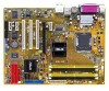
DIMM_B1 (64 bit,240-pin module) DDR2 DIMM_A1 (64 bit,240-pin module) DDR2 DIMM_A2 (64 bit,240-pin module) EATXPWR P5LD2 COM1 USB12 USBPW34 USBPW12 LGA775 LAN_USB34 Top: Back surround L/R Center: Side surround L/R Below:Bass Top:Line In Center:Line Out Below:Mic In Marvell 88E8053 PCIEX1_1 - Asus P5LD2 | Motherboard Installation Guide - Page 26
2-4 - Asus P5LD2 | Motherboard Installation Guide - Page 27
2-5 - Asus P5LD2 | Motherboard Installation Guide - Page 28
® ® • • • P5LD2 ® P5LD2 CPU Socket 775 2-6 - Asus P5LD2 | Motherboard Installation Guide - Page 29
A B B A 2-7 - Asus P5LD2 | Motherboard Installation Guide - Page 30
A B 2-8 - Asus P5LD2 | Motherboard Installation Guide - Page 31
® ® • ® ® ® • ® ® • 2-9 - Asus P5LD2 | Motherboard Installation Guide - Page 32
A B B A B A A B P5LD2 GND CPU FAN PWR CPU FAN IN CPU FAN PWM CPU_FAN ® P5LD2 CPU fan connector 2-10 - Asus P5LD2 | Motherboard Installation Guide - Page 33
A B B A B A A B 2-11 - Asus P5LD2 | Motherboard Installation Guide - Page 34
2-12 - Asus P5LD2 | Motherboard Installation Guide - Page 35
® P5LD2 DIMM sockets 2-13 P5LD2 DIMM_A1 DIMM_A2 DIMM_B1 DIMM_B2 - Asus P5LD2 | Motherboard Installation Guide - Page 36
2-14 - Asus P5LD2 | Motherboard Installation Guide - Page 37
2-15 - Asus P5LD2 | Motherboard Installation Guide - Page 38
2-16 - Asus P5LD2 | Motherboard Installation Guide - Page 39
2 3 1 • • 2 1 1 2-17 - Asus P5LD2 | Motherboard Installation Guide - Page 40
2-18 - Asus P5LD2 | Motherboard Installation Guide - Page 41
A B CD E F GH 2-19 - Asus P5LD2 | Motherboard Installation Guide - Page 42
2-20 - Asus P5LD2 | Motherboard Installation Guide - Page 43
P5LD2 ® P5LD2 Clear RTC RAM CLRTC 12 23 Normal (Default) Clear CMOS 2-21 - Asus P5LD2 | Motherboard Installation Guide - Page 44
USBPW34 USBPW12 12 23 P5LD2 +5V +5VSB (Default) USBPW56 ® USBPW78 12 23 +5V P5LD2 USB device wake-up +5VSB (Default) 2-22 KBPWR 12 23 +5V +5VSB (Default) P5LD2 ® P5LD2 Keyboard power setting - Asus P5LD2 | Motherboard Installation Guide - Page 45
1 2 3 45 67 15 14 13 12 11 10 9 8 2-23 - Asus P5LD2 | Motherboard Installation Guide - Page 46
2-24 - Asus P5LD2 | Motherboard Installation Guide - Page 47
P5LD2 FLOPPY R PIN 1 P5LD2 Floppy disk drive connector P5LD2 R P5LD2 RAID connectors SEC_EIDE PIN 1 PRI_EIDE PIN 1 2-25 - Asus P5LD2 | Motherboard Installation Guide - Page 48
• • PRI_IDE P5LD2 R P5LD2 IDE connector PIN 1 2-26 - Asus P5LD2 | Motherboard Installation Guide - Page 49
• • ® P5LD2 SATA connectors P5LD2 SATA4 GND RSATA_TXP1 RSATA_TXN1 GND RSATA_RXP1 RSATA_RXN1 GND GND RSATA_TXP2 RSATA_TXN2 GND RSATA_RXP2 RSATA_RXN2 GND SATA2 SATA3 SATA1 GND RSATA_TXP3 RSATA_TXN3 GND RSATA_RXP3 RSATA_RXN3 GND - Asus P5LD2 | Motherboard Installation Guide - Page 50
P5LD2 CD Right Audio Channel ® Ground Ground Left Audio Channel P5LD2 CD audio connector GND PRESENCE# SENSE1_RETUR SENSE2_RETUR AGND NC NC NC P5LD2 AAFP ® P5LD2 Analog front panel connector • • PORT1 L PORT1 R PORT2 R SENSE_SEND PORT2 L MIC2 MICPWR Line out_R NC Line out_L AC '97 audio pin - Asus P5LD2 | Motherboard Installation Guide - Page 51
2-29 P5LD2 Game connector P5LD2 GAME +5V J1B1 J1CX GND GND J1CY J1B2 +5V +5V J2B1 J2CX MIDI_OUT J2CY J2B2 MIDI_IN ® P5LD2 USB 2.0 connectors P5LD2 USB56 1 USB+5V USB_P5USB_P5+ GND USB+5V USB_P6USB_P6+ GND NC USB78 1 USB+5V USB_P7USB_P7+ GND USB+5V USB_P8USB_P8+ GND NC ® - Asus P5LD2 | Motherboard Installation Guide - Page 52
GND CPU FAN PWR CPU FAN IN CPU FAN PWM CPU_FAN PWR_FAN CHA_FAN2 CPU_FAN P5LD2 ® CHA_FAN1 P5LD2 Fan connectors CHA_FAN1 GND +12V Rotation Rotation +12V GND PWR_FAN GND +12V Rotation CHA_FAN2 P5LD2 +5VSB_MB Chassis Signal GND 2-30 ® CHASSIS P5LD2 Chassis intrusion connector (Default) - Asus P5LD2 | Motherboard Installation Guide - Page 53
ATX12V EATXPWR P5LD2 +12V DC GND ® P5LD2 ATX power connectors +12V DC +3 Volts GND +12 Volts +12 Volts +5V Standby Power OK Ground +5 Volts Ground +5 Volts Ground +3 Volts +3 Volts Ground +5 Volts +5 Volts +5 - Asus P5LD2 | Motherboard Installation Guide - Page 54
PLED SPEAKER PLED+ PLED+5V Ground Ground Speaker P5LD2 PANEL ® IDE_LED+ IDE_LED- PWR Ground Reset Ground IDE_LED RESET PWRSW P5LD2 System panel connector * Requires an ATX power supply. • 2-32 - Asus P5LD2 | Motherboard Installation Guide - Page 55
- Asus P5LD2 | Motherboard Installation Guide - Page 56
- Asus P5LD2 | Motherboard Installation Guide - Page 57
3-1 - Asus P5LD2 | Motherboard Installation Guide - Page 58
® ® ® ® 3-2 - Asus P5LD2 | Motherboard Installation Guide - Page 59
- Asus P5LD2 | Motherboard Installation Guide - Page 60
- Asus P5LD2 | Motherboard Installation Guide - Page 61
4-1 - Asus P5LD2 | Motherboard Installation Guide - Page 62
• • A:\>afudos /oOLDBIOS1.rom A:\>afudos /oOLDBIOS1.rom AMI Firmware Update Utility - Version 1.19 (ASUS V2.07(03.11.24BB)) Copyright (C) 2002 American Megatrends, Inc. All rights reserved. Reading flash ..... done Write to file ..... ok A:\> 4-2 - Asus P5LD2 | Motherboard Installation Guide - Page 63
A:\>afudos /iP5LD2.rom A:\>afudos /iP5LD2.ROM AMI Firmware Update Utility - Version 1.19 (ASUS V2.07(03.11.24BB)) Copyright (C) 2002 American Megatrends, Inc. All rights reserved. WARNING!! Do not turn off power during flash BIOS Reading file ..... done Reading flash .... done Advance Check .... - Asus P5LD2 | Motherboard Installation Guide - Page 64
A:\>afudos /iP5LD2.ROM AMI Firmware Update Utility - Version 1.10 Copyright (C) 2002 American Megatrends, Inc. All rights reserved. WARNING!! Do not turn off power during flash BIOS Reading file ..... done Reading flash .... done Advance Check .... Erasing flash .... done Writing flash .... done - Asus P5LD2 | Motherboard Installation Guide - Page 65
Bad BIOS checksum. Starting BIOS recovery... Checking for floppy... Bad BIOS checksum. Starting BIOS recovery... Checking for floppy... Floppy found! Reading file "P5LD2.ROM". Completed. Start flashing... 4-5 - Asus P5LD2 | Motherboard Installation Guide - Page 66
Bad BIOS checksum. Starting BIOS recovery... Checking for floppy... Bad BIOS checksum. Starting BIOS recovery... Checking for floppy... Floppy not found! Checking for CD-ROM... CD-ROM found. Reading file "P5LD2.ROM". Completed. Start flashing... 4-6 - Asus P5LD2 | Motherboard Installation Guide - Page 67
EZFlash starting BIOS update Checking for floppy... EZFlash starting BIOS update Checking for floppy... Floppy found! Reading file "P5LD2.ROM". Completed. Start erasing.......| Start Programming...| Flashed successfully. Rebooting. • • 4-7 - Asus P5LD2 | Motherboard Installation Guide - Page 68
4-8 - Asus P5LD2 | Motherboard Installation Guide - Page 69
4-9 - Asus P5LD2 | Motherboard Installation Guide - Page 70
4-10 - Asus P5LD2 | Motherboard Installation Guide - Page 71
4-11 - Asus P5LD2 | Motherboard Installation Guide - Page 72
IDE Slave Fourth IDE Master Fourth IDE Slave IDE Configuration System Information [11:51:19] [Thu 05/07/2004] [1.44M, 3.5 in] : [ST320413A] : [ASUS CD-S520/A] : [Not Detected] : [Not Detected] : [Not Detected] : [Not Detected] Use [ENTER], [TAB] or [SHIFT-TAB] to select a field. Use [+] or [-] to - Asus P5LD2 | Motherboard Installation Guide - Page 73
[11:10:19] [Thu 03/27/2003] [1.44M, 3.5 in] [English] :[ST320413A] :[ASUS CD-S340] :[Not Detected] :[Not Detected] :[Not Detected] :[Not Detected] Use [ENTER], [ may cause system to malfunction. Configure DRAM Timing by SPD Memory Acceleration Mode DRAM Idle Timer DRAm Refresh Rate [Enabled] - Asus P5LD2 | Motherboard Installation Guide - Page 74
IDE Slave Fourth IDE Master Fourth IDE Slave IDE Configuration System Information [11:51:19] [Thu 05/07/2004] [1.44M, 3.5 in] : [ST320413A] : [ASUS CD-S520/A] : [Not Detected] : [Not Detected] : [Not Detected] : [Not Detected] Use [ENTER], [TAB] or [SHIFT-TAB] to select a field. Use [+] or [-] to - Asus P5LD2 | Motherboard Installation Guide - Page 75
Block Mode : 16 Sectors PIO Mode : 4 Async DMA : MultiWord DMA-2 Ultra DMA : Ultra DMA-5 SMART Monitoring: Supported Type [Auto] LBA/Large Mode [Auto] Block(Multi-sector Transfer) [Auto] PIO Mode [Auto] DMA Mode [Auto] SMART Monitoring [Auto] 32Bit Data Transfer [Disabled - Asus P5LD2 | Motherboard Installation Guide - Page 76
IDE Configuration Configure SATA As Onboard IDE Operate Mode Enhanced Mode Support On [Standard IDE] [Enhanced Mode] [S-ATA] IDE Detect Time Out (Sec) [35] When in AHCI/RAID mode SATA controller is forced to Native mode. ® 4-16 - Asus P5LD2 | Motherboard Installation Guide - Page 77
4-17 - Asus P5LD2 | Motherboard Installation Guide - Page 78
AMIBIOS Version : 0106 Build Date : 04/15/05 Processor Type Speed Count : Genuine Intel(R) CPU 3.20GHz : 3200 MHz : 1 System Memory Total : 1024MB Appropriated : 0MB Available : 1024MB Select Screen Select Item +- Change Option F1 General Help F10 Save and Exit ESC Exit 4-18 - Asus P5LD2 | Motherboard Installation Guide - Page 79
system frequency/voltage. Configure System Frequency/Voltage AI Overclocking [Auto] Select the targe CPU frequency, and the relevant parameters will be auto-adjusted. Frequencies higher than CPU manufacturer recommends are not guaranteed to be stable. If the system becomes unstable, return - Asus P5LD2 | Motherboard Installation Guide - Page 80
FSB 1066 FSB 800 FSB 533 266 MHz 200 MHz 133 MHz 4-20 - Asus P5LD2 | Motherboard Installation Guide - Page 81
4-21 - Asus P5LD2 | Motherboard Installation Guide - Page 82
4-22 - Asus P5LD2 | Motherboard Installation Guide - Page 83
POST Check LAN Cable [Disabled] LAN Cable Status Pair Status Length 1-2 Normal N/A 3-6 Normal N/A 4-5 Normal N/A 7-8 Normal N/A Check LAN cable during POST. 4-23 - Asus P5LD2 | Motherboard Installation Guide - Page 84
USB Configuration Module Version - 2.23.2-9.4 USB Devices Enabled: None USB Function Legacy USB Support USB 2.0 Controller USB 2.0 Controller Mode BIOS EHCI Hand-Off [Enabled] [Auto] [Enabled] [HiSpeed] [Disabled] Enables USB host controllers. 4-24 - Asus P5LD2 | Motherboard Installation Guide - Page 85
Setting: [ 14] VID CMOS Setting: [ 62] CPU Lock Free [Auto] Microcode Updation [Enabled] Max CPUID Value Limit: [Disabled] Execute Disable Function [Disabled] Enhanced C1 Control [Auto] CPU Internal Thermal Control [Auto] Sets the ratio between CPU Core Clock and the FSB Frequency - Asus P5LD2 | Motherboard Installation Guide - Page 86
4-26 - Asus P5LD2 | Motherboard Installation Guide - Page 87
Advanced Chipset Settings Configure DRAM Timing by SPD Hyper Path 3 Booting Graphic Adapter Priori PEG Buffer Length Link Latency PEG Root Control PEG Link Mode Slot Power High Priority Port Select [Enabled] [Auto] [PCI Express/PCI] [Auto] [Auto] [Auto] [Auto] [Auto] [Disabled] Enable or disable - Asus P5LD2 | Motherboard Installation Guide - Page 88
4-28 - Asus P5LD2 | Motherboard Installation Guide - Page 89
Configure Win627EHF Super IO Chipset HD Audio Controller Front Panel Support Type Onboard PCIEX GbE LAN LAN Option ROM ITE8211F Controller Detecting Device Time [Enabled] [HD Audio] [Enabled] [Disabled] [IDE Mode] [Quick Mode] Serial Port1 Address Parallel Port Address Parallel Port Mode ECP Mode - Asus P5LD2 | Motherboard Installation Guide - Page 90
® 4-30 - Asus P5LD2 | Motherboard Installation Guide - Page 91
-15 assigned to [PCI Device] [PCI Device] [PCI Device] [PCI Device] [PCI Device] [PCI Device] [PCI Device] [PCI Device] [PCI Device] NO: Lets the BIOS configue all the devices in the system. YES: Lets the operating system configure Plug and Play (PnP) devices not required for boot if your system - Asus P5LD2 | Motherboard Installation Guide - Page 92
4-32 - Asus P5LD2 | Motherboard Installation Guide - Page 93
Suspend Mode Repost Video on S3 Resume ACPI 2.0 Support ACPI APIC Support APM Configuration Hardware Monitor [Auto] [No] [No] [Enabled] Select the ACPI state used for System Suspend. 4-33 - Asus P5LD2 | Motherboard Installation Guide - Page 94
APM Configuration Power Button Mode [On/Off] Restore on AC Power Loss Power On By RTC Alarm Power On By External Modems Power On By PCI Devices Power On By PCIE Devices Power On By PS/2 Keyboard Power On By PS/2 Mouse [Power Off] [Disabled] [Disabled] [Disabled] [Disabled] [Disabled] [Disabled] - Asus P5LD2 | Motherboard Installation Guide - Page 95
4-35 - Asus P5LD2 | Motherboard Installation Guide - Page 96
Hardware Monitor AI Quiet CPU Q-Fan Control [Disabled] [Disabled] CPU Temperature MB Temperature [32.5ºC/90.5ºF] [36.0ºC/96.5ºF] CPU Fan Speed (RPM) Chassis Fan1 Speed (RPM) Chassis Fan2 Speed (RPM) Power Fan Speed (RPM) [3813RPM] [N/A] [N/A] [N/A] VCORE Voltage 3.3V Voltage 5V Voltage 12V - Asus P5LD2 | Motherboard Installation Guide - Page 97
4-37 - Asus P5LD2 | Motherboard Installation Guide - Page 98
Help F10 Save and Exit ESC Exit Boot Device Priority 1st Boot Device 2nd Boot Device 3rd Boot Device [1st FLOPPY DRIVE] [PM-ST330620A] [PS-ASUS CD-S360] Select Screen Select Item Enter Go to Sub-screen F1 General Help F10 Save and Exit ESC Exit 4-38 - Asus P5LD2 | Motherboard Installation Guide - Page 99
Full Screen Logo AddOn ROM Display Mode Bootup Num-Lock PS/2 Mouse Support Wait For 'F1' If Error Hit 'DEL' Message Display Interrupt 19 Capture [Enabled] [Enabled] [Force BIOS] [On] [Auto] [Enabled] [Enabled] [Disabled] Allows BIOS to skip certain tests while booting. This will decrease the time - Asus P5LD2 | Motherboard Installation Guide - Page 100
Security Settings Supervisor Password User Password : Not Installed : Not Installed Change Supervisor Password to change password. again to disabled password. Select Screen Select Item +- Change Option F1 General Help F10 Save and Exit ESC Exit 4-40 - Asus P5LD2 | Motherboard Installation Guide - Page 101
Security Settings Supervisor Password User Password : Not Installed : Not Installed Change Supervisor Password User Access Level Change User Password Clear User Password Password Check [Full Access] [Setup] Select Screen Select Item +- Change Option F1 General Help F10 Save and Exit ESC Exit 4- - Asus P5LD2 | Motherboard Installation Guide - Page 102
4-42 - Asus P5LD2 | Motherboard Installation Guide - Page 103
Exit Options Exit & Save Changes Exit & Discard Changes Discard Changes Load Setup Defaults Exit system setup after saving the changes. F10 key can be used for this operation. Select Screen Select Item Enter Go to Sub-screen F1 General Help F10 Save and Exit ESC Exit 4-43 - Asus P5LD2 | Motherboard Installation Guide - Page 104
4-44 - Asus P5LD2 | Motherboard Installation Guide - Page 105
- Asus P5LD2 | Motherboard Installation Guide - Page 106
- Asus P5LD2 | Motherboard Installation Guide - Page 107
5-1 - Asus P5LD2 | Motherboard Installation Guide - Page 108
® 5-2 - Asus P5LD2 | Motherboard Installation Guide - Page 109
5-3 - Asus P5LD2 | Motherboard Installation Guide - Page 110
5-4 - Asus P5LD2 | Motherboard Installation Guide - Page 111
5-5 - Asus P5LD2 | Motherboard Installation Guide - Page 112
5-6 - Asus P5LD2 | Motherboard Installation Guide - Page 113
5-7 - Asus P5LD2 | Motherboard Installation Guide - Page 114
5-8 - Asus P5LD2 | Motherboard Installation Guide - Page 115
5-9 - Asus P5LD2 | Motherboard Installation Guide - Page 116
5-10 - Asus P5LD2 | Motherboard Installation Guide - Page 117
5-11 - Asus P5LD2 | Motherboard Installation Guide - Page 118
5-12 - Asus P5LD2 | Motherboard Installation Guide - Page 119
5-13 - Asus P5LD2 | Motherboard Installation Guide - Page 120
5-14 - Asus P5LD2 | Motherboard Installation Guide - Page 121
5-15 - Asus P5LD2 | Motherboard Installation Guide - Page 122
5-16 - Asus P5LD2 | Motherboard Installation Guide - Page 123
® ® ® ® 5-17 - Asus P5LD2 | Motherboard Installation Guide - Page 124
® 5-18 - Asus P5LD2 | Motherboard Installation Guide - Page 125
1032 ICH7R wRAID5 Copyright(C) 2003-05 Intel Corporation. All Rights Reserved. [ MAIN MENU ] 1. Create RAID Volume 2. Delete RAID Volume 3. Reset Disks to Non-RAID 4. Exit RAID Volumes: None defined. Physical Disks: Port Drive Model 0 XXXXXXXXXXX 1 XXXXXXXXXXX 2 XXXXXXXXXXX 3 XXXXXXXXXXX [ DISK - Asus P5LD2 | Motherboard Installation Guide - Page 126
Intel(R) Matrix Storage Manager Option ROM v5.0.0.1032 ICH7R wRAID5 Copyright(C) 2003-05 Intel Corporation. All Rights Reserved. [ CREATE ARRAY MENU ] Name: RAID Level: Disks: Strip Size: Capacity: Volume0 RAID0(Stripe) Select Disks 128KB 0.0 GB Create Volume [ DISK/VOLUME INFORMATION ] Enter a - Asus P5LD2 | Motherboard Installation Guide - Page 127
• • • WARNING: ALL DATA ON SELECTED DISKS WILL BE LOST. Are you sure you want to create this volume? (Y/N): 5-21 - Asus P5LD2 | Motherboard Installation Guide - Page 128
Intel(R) Matrix Storage Manager Option ROM v5.0.0.1032 ICH7R wRAID5 Copyright(C) 2003-05 Intel Corporation. All Rights Reserved. [ CREATE ARRAY MENU ] Name: RAID Level: Disks: Strip Size: Capacity: Volume1 RAID1(Mirror) Select Disks N/A XX.X GB Create Volume [ DISK/VOLUME INFORMATION ] Enter a - Asus P5LD2 | Motherboard Installation Guide - Page 129
Intel(R) Matrix Storage Manager Option ROM v5.0.0.1032 ICH7R wRAID5 Copyright(C) 2003-05 Intel Corporation. All Rights Reserved. [ CREATE ARRAY MENU ] Name: RAID Level: Disks: Strip Size: Capacity: Volume10 RAID10(RAID0+1) Select Disks 128KB XXX.X GB Create Volume [ DISK/VOLUME INFORMATION ] - Asus P5LD2 | Motherboard Installation Guide - Page 130
WARNING: ALL DATA ON SELECTED DISKS WILL BE LOST. Are you sure you want to create this volume? (Y/N): Intel(R) Matrix Storage Manager Option ROM v5.0.0.1032 ICH7R wRAID5 Copyright(C) 2003-05 Intel Corporation. All Rights Reserved. [ CREATE ARRAY MENU ] Name: RAID Level: Disks: Strip Size: Capacity - Asus P5LD2 | Motherboard Installation Guide - Page 131
Port Drive Model 0 XXXXXXXXXXXX 1 XXXXXXXXXXXX 2 XXXXXXXXXXXX 3 XXXXXXXXXXXX [ SELECT DISKS ] Serial # XXXXXXXX XXXXXXXX XXXXXXXX XXXXXXXX Size Status XX.XGB Non-RAID Disk XX.XGB Non-RAID Disk XX.XGB Non-RAID Disk XX.XGB Non-RAID Disk Select 2 to 4 disks to use in creating the volume. [↑↓]- - Asus P5LD2 | Motherboard Installation Guide - Page 132
Intel(R) Matrix Storage Manager Option ROM v5.0.0.1032 ICH7R wRAID5 Copyright(C) 2003-05 Intel Corporation. All Rights Reserved. [ DELETE VOLUME MENU ] Name Volume0 Level RAIDX(xxxxx) Drives X Capacity Status XXX.XGB Normal Bootable Yes [ HELP ] Deleting a volume will destroy the volume - Asus P5LD2 | Motherboard Installation Guide - Page 133
internal RAID structures from the selected RAID disks. By removing these structures, the drive will revert back to a non-RAID disk. WARNING: Resetting a disk causes all data on the disk to be lost. Port Drive Model 0 XXXXXXXXXXXX 1 XXXXXXXXXXXX Serial # XXXXXXXX XXXXXXXX Size Status XX.XGB - Asus P5LD2 | Motherboard Installation Guide - Page 134
the internal RAID structures from the selected RAID disks. By removing these structures the drive will revert back to a Non-RAID disk. WARNING: Resetting a disk causes all data on the disk to be lost. Port Drive Model 0 STXXXXXXXXX 1 STXXXXXXXXX Serial # XXXXXXXX XXXXXXXX Size XX.0GB XX.0GB - Asus P5LD2 | Motherboard Installation Guide - Page 135
Loading FreeDOS FAT KERNEL GO! Press any key to boot from CDROM... 1) Make ICH7 32-bit RAID driver disk 2) Make ICH7 64-bit RAID driver disk 3) Format floppy disk 4) FreeDOS command prompt Please choose 1 ~ 4 Insert new diskette for drive B:\ and press ENTER when ready... Please insert your - Asus P5LD2 | Motherboard Installation Guide - Page 136
• • • 5-30 - Asus P5LD2 | Motherboard Installation Guide - Page 137
- Asus P5LD2 | Motherboard Installation Guide - Page 138
® ® ® - Asus P5LD2 | Motherboard Installation Guide - Page 139
® ® ® ® ® ® ® ® ® ® ® A-1 - Asus P5LD2 | Motherboard Installation Guide - Page 140
A-2 - Asus P5LD2 | Motherboard Installation Guide - Page 141
® ® ® ® ® ® ® ® A-3 - Asus P5LD2 | Motherboard Installation Guide - Page 142
A-4 - Asus P5LD2 | Motherboard Installation Guide - Page 143
A-5 - Asus P5LD2 | Motherboard Installation Guide - Page 144
A-6
-
 1
1 -
 2
2 -
 3
3 -
 4
4 -
 5
5 -
 6
6 -
 7
7 -
8
-
9
-
10
-
11
-
12
-
13
-
14
-
15
-
16
-
17
-
18
-
19
-
20
-
21
-
22
-
23
-
24
-
25
-
26
-
27
-
28
-
29
-
30
-
31
-
32
-
33
-
34
-
35
-
36
-
37
-
38
-
39
-
40
-
41
-
42
-
43
-
44
-
45
-
46
-
47
-
48
-
49
-
50
-
51
-
52
-
53
-
54
-
55
-
56
-
57
-
58
-
59
-
60
-
61
-
62
-
63
-
64
-
65
-
66
-
67
-
68
-
69
-
70
-
71
-
72
-
73
-
74
-
75
-
76
-
77
-
78
-
79
-
80
-
81
-
82
-
83
-
84
-
85
-
86
-
87
-
88
-
89
-
90
-
91
-
92
-
93
-
94
-
95
-
96
-
97
-
98
-
99
-
100
-
101
-
102
-
103
-
104
-
105
-
106
-
107
-
108
-
109
-
110
-
111
-
112
-
113
-
114
-
115
-
116
-
117
-
118
-
119
-
120
-
121
-
122
-
123
-
124
-
125
-
126
-
127
-
128
-
129
-
130
-
131
-
132
-
133
-
134
-
135
-
136
-
137
-
138
-
139
-
140
-
141
-
142
-
143
-
144
 |
 |

Motherboard
P5LD2