Asus P5RD1-V Motherboard Installation Guide
Asus P5RD1-V Manual
 |
View all Asus P5RD1-V manuals
Add to My Manuals
Save this manual to your list of manuals |
Asus P5RD1-V manual content summary:
- Asus P5RD1-V | Motherboard Installation Guide - Page 1
P5RD1-V Motherboard - Asus P5RD1-V | Motherboard Installation Guide - Page 2
express written permission of ASUSTeK COMPUTER INC. ("ASUS"). Product warranty or service will not be extended if: (1) the ASUS HAS BEEN ADVISED OF THE POSSIBILITY OF SUCH DAMAGES ARISING FROM ANY DEFECT OR ERROR IN THIS MANUAL OR PRODUCT. SPECIFICATIONS AND INFORMATION CONTAINED IN THIS MANUAL - Asus P5RD1-V | Motherboard Installation Guide - Page 3
used in this guide x Typography x P5RD1-V specifications summary xi Chapter 1: Product introduction 1.1 Welcome 1-1 1.2 Package contents 1-1 1.3 Special features 1-2 1.3.1 Product highlights 1-2 1.3.2 ASUS Proactive features 1-4 1.3.3 Innovative ASUS features 1-5 Chapter 2: Hardware - Asus P5RD1-V | Motherboard Installation Guide - Page 4
BIOS 2 utility 4-5 4.1.4 ASUS EZ Flash utility 4-7 4.1.5 ASUS Update utility 4-8 4.2 BIOS setup program 4-11 4.2.1 BIOS menu screen 4-12 4.2.2 Menu bar 4-12 4.2.3 Navigation keys 4-12 4.2.4 Menu items 4-13 4.2.5 Sub-menu items 4-13 4.2.6 Configuration fields 4-13 4.2.7 Pop-up window - Asus P5RD1-V | Motherboard Installation Guide - Page 5
JumperFree Configuration 4-18 4.4.3 LAN Cable Status 4-21 4.4.4 CPU Configuration 4-22 4.4.5 Chipset 4-24 4.4.6 Onboard Devices Configuration 4-27 4.4.7 PCI PnP 4-28 4.5 Power menu 4-29 4.5.1 Suspend Mode 4-29 4.5.2 Repost Video on S3 Resume 4-29 4.5.3 ACPI 2.0 Support 4-29 4.5.4 ACPI APIC - Asus P5RD1-V | Motherboard Installation Guide - Page 6
Using the Virtual Cable Tester 5-9 5.4.3 Audio configurations 5-10 5.5 RAID configurations 5-16 5.5.1 Installing hard disks 5-16 5.5.2 ULI® RAID configurations 5-17 5.6 Creating a RAID driver disk 5-22 Appendix: CPU features A.1 Enhanced Intel SpeedStep® Technology (EIST A-1 A.1.1 System - Asus P5RD1-V | Motherboard Installation Guide - Page 7
. This equipment generates, uses and can radiate radio frequency energy and, if not installed and used in accordance with manufacturer's instructions, may cause harmful interference to radio communications. However, there is no guarantee that interference will not occur in a particular installation - Asus P5RD1-V | Motherboard Installation Guide - Page 8
Contact a qualified service technician or your retailer. Operation safety • Before installing the motherboard and adding devices on it, carefully read all the manuals that came with • If you encounter technical problems with the product, contact a qualified service technician or your retailer. viii - Asus P5RD1-V | Motherboard Installation Guide - Page 9
the BIOS parameters are also provided. • Chapter 5: Software support This chapter describes the contents of the support CD that comes with the motherboard package. Where to find more information Refer to the following sources for additional information and for product and software updates. 1. ASUS - Asus P5RD1-V | Motherboard Installation Guide - Page 10
following symbols used throughout this manual. D A N G E R / W A R N I N G : Information to prevent injury to yourself when trying to complete a task. C A U T I O N : Information to prevent damage to the components when trying to complete a task. I M P O R T A N T : Instructions that you MUST follow - Asus P5RD1-V | Motherboard Installation Guide - Page 11
P5RD1-V specifications summary CPU Chipset Front Side Bus Memory Expansion slots Integrated Graphics Storage High Definition Audio LAN Overclocking features USB LGA775 socket for Intel® Pentium® 4/Celeron processor Compatible with the Intel® PCG 04A and 04B processors Supports Intel® Hyper- - Asus P5RD1-V | Motherboard Installation Guide - Page 12
P5RD1-V specifications summary ASUS Special features BIOS features Rear panel Internal connectors Power requirement Form Factor Support CD contents ASUS Q-Fan2 ASUS CrashFree BIOS 2 ASUS MyLogo2 4 MB Flash ROM, AMI BIOS, PnP, DMI2.0, SM BIOS 2.3, WfM2.0 1 x Parallel port 1 x VGA port 1 x LAN (RJ- - Asus P5RD1-V | Motherboard Installation Guide - Page 13
This chapter describes the motherboard features and the new technologies it supports. 1Product introduction - Asus P5RD1-V | Motherboard Installation Guide - Page 14
Chapter summary 1.1 Welcome 1-1 1.2 Package contents 1-1 1.3 Special features 1-2 ASUS P5RD1-V - Asus P5RD1-V | Motherboard Installation Guide - Page 15
(dual plugs) 1 x Ultra DMA/133 cables 40-conductor IDE cable Floppy disk drive cable Accessories I/O shield A p p l i c a t i o n C D s ASUS motherboard support CD D o c u m e n t a t i o n User guide If any of the above items is damaged or missing, contact your retailer. ASUS P5RD1-V 1-1 - Asus P5RD1-V | Motherboard Installation Guide - Page 16
Front Side Bus (FSB). The motherboard also supports the Intel® Hyper-Threading Technology, Enhanced Intel SpeedStep® Technology, and is fully compatible with Intel® 04B and 04A processors. See page 2-6 for details. ATI RADEON® XPRESS 200/ULI M1573 chipset The ATI RADEON® XPRESS 200 Northbridge and - Asus P5RD1-V | Motherboard Installation Guide - Page 17
The onboard ULI® M1573 allows RAID 0, RAID 1, RAID 0+1, or JBOD configuration for four SATA connectors. See pages 2-26 and 5-16 for details. PCI Express™ interface The motherboard fully supports PCI Express, the latest I/O interconnect technology that speeds up the PCI bus. PCI Express features - Asus P5RD1-V | Motherboard Installation Guide - Page 18
LAN cable(s) and reports shorts and faults up to 100 meters at 1 meter accuracy. See pages 4-21 and 5-9 for details. 1.3.3 Innovative ASUS features CrashFree BIOS 2 This feature allows you to restore the original BIOS data from the support ASUS MyLogo2™ This new feature present in the motherboard - Asus P5RD1-V | Motherboard Installation Guide - Page 19
This chapter lists the hardware setup procedures that you have to perform when installing system components. It includes description of the jumpers and connectors on the motherboard. 2 Hardware information - Asus P5RD1-V | Motherboard Installation Guide - Page 20
Chapter summary 2.1 Before you proceed 2-1 2.2 Motherboard overview 2-2 2.3 Central Processing Unit (CPU 2-6 2.4 System memory 2-13 2.5 Expansion slots 2-17 2.6 Jumpers 2-20 2.7 Connectors 2-23 ASUS P5RD1-V - Asus P5RD1-V | Motherboard Installation Guide - Page 21
motherboard components or change any motherboard may cause severe damage to the motherboard, peripherals, and/or components. Onboard LED The motherboard comes with a standby power motherboard component. The illustration below shows the location of the onboard LED. P5RD1-V ® SB_PWR P5RD1-V Onboard - Asus P5RD1-V | Motherboard Installation Guide - Page 22
or removing the motherboard. Failure to do so can cause you physical injury and damage motherboard components. 2.2.1 Placement direction When installing the motherboard, make sure indicated by circles to secure the motherboard to the chassis. Do not overtighten the screws! Doing so can damage the - Asus P5RD1-V | Motherboard Installation Guide - Page 23
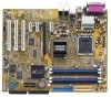
(12.0in) 2.2.3 Motherboard layout 24.5cm (9. Center:Line Out Below:Mic In CHA_FAN1 PCIEX1_1 TV_OUT ATI RADEON XPRESS 200 P5RD1-V PCIEX16 R PCIEX1_2 PCIEX1_3 Marvell 88E8001 PCI1 SPDIF_OUT BIOS LPC Super I/O CHASSIS COM1 USB78 USB56 GAME PANEL PRI_IDE FLOPPY SEC_IDE ASUS P5RD1-V 2-3 - Asus P5RD1-V | Motherboard Installation Guide - Page 24
Slots 1. DDR DIMM slots 2. PCI slots 3. PCI Express slot Page 2-13 2-19 2-19 Jumpers 1. Clear RTC RAM (3-pin CLRTC) 2. USB Device wake-up (3-pin USBPW12, USBPW34, USBPW56, USBPW78) 3. CPU Fan type selector (3-pin FANSEL) Page 2-20 2-21 2-22 Rear panel connectors 1. Parallel port 2. RJ-45 port - Asus P5RD1-V | Motherboard Installation Guide - Page 25
ATA connectors (7-pin SATA1, SATA2, SATA3, SATA4) 5. CPU fan connector (4-pin CPU_FAN) 6. Power fan connector (3-pin PWR_FAN GAME) 14. Chassis intrusion connector (4-1 pin CHASSIS) 15. Front panel audio connector (10-1 pin AAFP) 16. TV-out connector (6-1 pin TV_OUT 2-32 2-32 2-33 ASUS P5RD1-V 2-5 - Asus P5RD1-V | Motherboard Installation Guide - Page 26
Unit (CPU) The motherboard comes with a surface mount LGA775 socket designed for the Intel® Pentium® 4 processor in the 775-land package. • Your boxed Intel® Pentium® 4 LGA775 processor package should come with installation instructions for the CPU, fan and heatsink assembly. If the instructions in - Asus P5RD1-V | Motherboard Installation Guide - Page 27
the socket pins, do not remove the PnP cap unless you are installing a CPU. 3. Lift the load lever in the direction of the arrow to a 135º (A), then push the PnP cap B from the load plate window to remove (B). Load plate 5. Position the CPU over the socket, making sure that the gold triangle is - Asus P5RD1-V | Motherboard Installation Guide - Page 28
snaps into the retention tab. B The motherboard supports Intel® Pentium® 4 LGA775 processors with the Intel® Enhanced Intel SpeedStep® Technology (EIST) and Intel® Hyper-Threading Technology. Refer to the Appendix for more information on these CPU features. 2-8 Chapter 2: Hardware information - Asus P5RD1-V | Motherboard Installation Guide - Page 29
heatsink and fan assembly such that the CPU fan cable is closest to the CPU fan connector. Narrow end of the groove Motherboard hole Fastener Make sure to orient each fastener with the narrow end of the groove pointing outward. (The photo shows the groove shaded for emphasis.) ASUS P5RD1-V 2-9 - Asus P5RD1-V | Motherboard Installation Guide - Page 30
fan assembly in A place. A B A B B A 3. Connect the CPU fan cable to the connector on the motherboard labeled CPU_FAN. P5RD1-V ® CPU_FAN CPU FAN PWM CPU FAN IN CPU FAN PWR GND P5RD1-V CPU fan connector Do not forget to connect the CPU fan connector! Hardware monitoring errors can occur - Asus P5RD1-V | Motherboard Installation Guide - Page 31
CPU heatsink and fan: 1. Disconnect the CPU fan cable from the connector on the motherboard. 2. Rotate each fastener counterclockwise. 3. Pull up two fasteners at a time in a diagonal sequence to disengage the heatsink B and fan assembly from the A A motherboard. B A B B A ASUS P5RD1 - Asus P5RD1-V | Motherboard Installation Guide - Page 32
4. Carefully remove the heatsink and fan assembly from the motherboard. 5. Rotate each fastener clockwise to ensure correct orientation when reinstalling. The narrow end of the groove should point outward after resetting. (The photo shows the - Asus P5RD1-V | Motherboard Installation Guide - Page 33
install DIMMs with the same CAS latency. For optimum compatibility, it is recommended that you obtain memory modules from the same vendor. • Due to chipset resource allocation, the system may detect less than 4 GB system memory when you installed four 1 GB DDR memory modules. ASUS P5RD1-V 2-13 - Asus P5RD1-V | Motherboard Installation Guide - Page 34
Table 1 Recommended memory configurations Mode Single-channel Dual-channel DIMM_A1 (blue) (1) Populated (2) - (3) - (4) - (1) Populated (2) - (3) Apacer 256MB Apacer 512MB Apacer 256MB A DATA Model DIMM support Brand Side(s) Component ABC KVR400X64C3A/256 Hynix SS HY5DU56822BT-D43 - Asus P5RD1-V | Motherboard Installation Guide - Page 35
- supports on pair of modules inserted into either the blue slots or the black slots as one pair of Dual-channel memory configuration. C - support for 4 modules inserted into the blue and black slots as two pairs of Dual-channel memory configuration. S S - Single-sided D S - Double-sided ASUS P5RD1 - Asus P5RD1-V | Motherboard Installation Guide - Page 36
components. Failure to do so may cause severe damage to both the motherboard and the components. 1. Unlock a DIMM socket by pressing the retaining clips retaining clips outward to unlock the DIMM. 1 1 DDR DIMM notch Support the DIMM lightly with your fingers when pressing the retaining clips. The - Asus P5RD1-V | Motherboard Installation Guide - Page 37
cards that they support. Make sure to unit cover (if your motherboard is already installed in a BIOS settings, if any. See Chapter 4 for information on BIOS setup. 2. Assign an IRQ to the card. Refer to the tables on the next page. 3. Install the software drivers for the expansion card. ASUS P5RD1 - Asus P5RD1-V | Motherboard Installation Guide - Page 38
for ISA or PCI devices. IRQ assignments for this motherboard PCI slot 1 PCI slot 2 PCI slot 3 PCI USB controller 3 Onboard USB 2.0 controller Onboard LAN Onboard HD audio A B C D E F G H using PCI cards on shared slots, ensure that the drivers support "Share IRQ" or that the cards do not - Asus P5RD1-V | Motherboard Installation Guide - Page 39
graphics card installed on the PCI Express x16 slot. 2.5.6 PCI Express x1 slot This motherboard supports PCI Express x1 network cards, SCSI cards and other cards that comply with the PCI Express specifications. The figure shows a network card installed on the PCI Express x1 slot. ASUS P5RD1-V 2-19 - Asus P5RD1-V | Motherboard Installation Guide - Page 40
failure! P5RD1-V ® P5RD1-V Clear RTC RAM CLRTC 2 1 Normal (Default) 3 2 Clear CMOS You do not need to clear the RTC when the system hangs due to overclocking. For system failure due to overclocking, use the C.P.R. (CPU Parameter Recall) feature. Shut down and reboot the system so the BIOS can - Asus P5RD1-V | Motherboard Installation Guide - Page 41
connected USB devices. Set to +5VSB to wake up from S3 and S4 sleep modes (no power to CPU, DRAM in slow refresh, power supply in reduced power mode). The USBPWR12 and USBPWR34 jumpers are for the power supply capability (+5VSB) whether under normal condition or in sleep mode. ASUS P5RD1-V 2-21 - Asus P5RD1-V | Motherboard Installation Guide - Page 42
a 3-pin or a 4-pin fan cable plug to the CPU fan connector (CPU_FAN). Set this jumper to pins 1-2 if you are using a 4-pin fan cable plug, or to pins 2-3 if you are using a 3-pin plug. P5RD1-V R FANSEL 2 1 4-pin (Default) 3 2 3-pin P5RD1-V FANPWR setting 2-22 Chapter 2: Hardware information - Asus P5RD1-V | Motherboard Installation Guide - Page 43
(LAN) through a network hub. Refer to the table below for the LAN port LED indications. LAN port port connects the center/subwoofer speakers. Refer to the audio configuration table on the next page for the function of the audio ports in 2, 4, 6, or 8-channel configuration. ASUS P5RD1-V 2-23 - Asus P5RD1-V | Motherboard Installation Guide - Page 44
Audio 2, 4, 6, or 8-channel configuration Port Light Blue Lime Pink Gray Black Yellow Orange Headset 2-channel Line In Line Out Mic In • • • 4-channel Line In Front Speaker - Asus P5RD1-V | Motherboard Installation Guide - Page 45
. This prevents incorrect insertion when you connect the IDE cable. • Use the 80-conductor IDE cable for Ultra DMA 133/100/66 IDE devices. PRI_IDE P5RD1-V ® P5RD1-V IDE connectors ASUS P5RD1-V NOTE: Orient the red markings (usually zigzag) on the IDE ribbon cable to PIN 1. PIN 1 SEC_IDE 2-25 - Asus P5RD1-V | Motherboard Installation Guide - Page 46
GND SATA2 GND RSATA_TXP2 RSATA_TXN2 GND RSATA_RXP2 RSATA_RXN2 GND • Due to chipset limitation, you cannot configure a RAID 0 set or JBOD with more than two hard disk drives. • Install the Windows® 2000 Service Pack 4 or the Windows® XP Service Pack1 or later when using Serial ATA. 2-26 Chapter - Asus P5RD1-V | Motherboard Installation Guide - Page 47
damage the motherboard components. These are not jumpers! DO NOT place jumper caps on the fan connectors! • The ASUS Q-Fan2 function is supported using the CPU Fan (CPU_FAN) and Chassis Fan 1 (CHA_FAN1) connectors only. P5RD1-V ® CPU_FAN CHA_FAN1 PWR_FAN CPU_FAN CPU FAN PWM CPU FAN IN CPU FAN - Asus P5RD1-V | Motherboard Installation Guide - Page 48
module to a slot opening at the back of the system chassis. These USB connectors comply with USB 2.0 specification that supports up to 480 Mbps connection speed. USB+5V USB_P6USB_P6+ GND NC USB+5V USB_P8USB_P8+ GND NC P5RD1-V ® USB78 1 USB56 1 USB+5V USB_P5USB_P5+ GND USB+5V USB_P7USB_P7+ GND - Asus P5RD1-V | Motherboard Installation Guide - Page 49
until the connectors completely fit. • Use of an ATX 12 V Specification 2.0-compliant power supply unit (PSU) that provides a minimum power installing an add-on PCI Express x16 graphics card. EATXPWR P5RD1-V ® ATX12V +12V DC GND +12V DC GND P5RD1-V ATX power connectors +3 Volts +12 Volts +12 - Asus P5RD1-V | Motherboard Installation Guide - Page 50
system chassis. The GAME/MIDI port connects a joystick or game pad for playing games, and MIDI devices for playing or editing audio files. +5V J2B1 J2CX MIDI_OUT J2CY J2B2 MIDI_IN P5RD1-V ® P5RD1-V GAME connector GAME +5V J1B1 J1CX GND GND J1CY J1B2 +5V 2-30 Chapter 2: Hardware information - Asus P5RD1-V | Motherboard Installation Guide - Page 51
-definition audio front panel audio I/O to use the high-definition audio features. • The default setting of this connector is legacy AC'97 audio, if you want to use the High-Definition (Azalia) audio features, set the A C 9 7 & A z a l i a L I N K A in the BIOS to Azalia. See page 4-26. ASUS P5RD1 - Asus P5RD1-V | Motherboard Installation Guide - Page 52
connector is for the S/PDIF audio module to allow digital sound output. Connect one end of the S/PDIF audio cable to this connector and the other end to the S/PDIF module. The S/PDIF module is purchased separately. +5V SPDIFOUT GND P5RD1-V ® SPDIF_OUT P5RD1-V Digital audio connector 13. TV-out - Asus P5RD1-V | Motherboard Installation Guide - Page 53
supports several chassis-mounted functions. PLED SPEAKER PLED+ PLED+5V Ground Ground Speaker P5RD1-V ® PANEL IDE_LED+ IDE_LED- PWR Ground Reset Ground IDE LED P5RD1 the system in SLEEP or SOFT-OFF mode depending on the BIOS settings. Pressing the power switch for more than four seconds while - Asus P5RD1-V | Motherboard Installation Guide - Page 54
2-34 Chapter 2: Hardware information - Asus P5RD1-V | Motherboard Installation Guide - Page 55
This chapter describes the power up Powerin3g up sequence, the vocal POST messages, and ways of shutting down the system. - Asus P5RD1-V | Motherboard Installation Guide - Page 56
Chapter summary 3.1 Starting up for the first time 3-1 3.2 Powering off the computer 3-2 ASUS P5RD1-V - Asus P5RD1-V | Motherboard Installation Guide - Page 57
then runs the power-on self tests or POST. While the tests are running, the BIOS beeps (see BIOS beep codes table below) or additional messages appear on the screen. If you do not see on, hold down the key to enter the BIOS Setup. Follow the instructions in Chapter 4. ASUS P5RD1-V 3-1 - Asus P5RD1-V | Motherboard Installation Guide - Page 58
to shut down the computer. 3. The power supply should turn off after Windows® shuts down. If you are using Windows® XP: 1. Click the S t a r t button then select T u BIOS setting. Pressing the power switch for more than four seconds lets the system enter the soft-off mode regardless of the BIOS - Asus P5RD1-V | Motherboard Installation Guide - Page 59
This chapter tells how to change the system settings through the BIOS Setup menus. Detailed descriptions of the BIOS parameters are also provided. 4 BIOS setup - Asus P5RD1-V | Motherboard Installation Guide - Page 60
Chapter summary 4.1 Managing and updating your BIOS 4-1 4.2 BIOS setup program 4-11 4.3 Main menu 4-14 4.4 Advanced menu 4-17 4.5 Power menu 4-29 4.6 Boot menu 4-33 4.7 Exit menu 4-37 ASUS P5RD1-V - Asus P5RD1-V | Motherboard Installation Guide - Page 61
motherboard BIOS using the ASUS Update or AFUDOS utilities. 4.1.1 Creating a bootable floppy disk 1. Do either one of the following to create a bootable floppy disk. DOS environment a. Insert a 1.44MB floppy disk into the drive. b. At the DOS prompt, type format A:/S then press . Windows® XP - Asus P5RD1-V | Motherboard Installation Guide - Page 62
is your optical drive. e. Press , then follow screen instructions to continue. 2. Copy the original or the latest motherboard BIOS file to the bootable floppy disk. 4.1.2 AFUDOS utility The AFUDOS utility allows you to update the BIOS file in DOS environment using a bootable floppy disk with - Asus P5RD1-V | Motherboard Installation Guide - Page 63
The utility returns to the DOS prompt after copying the current BIOS file. Updating the BIOS file To update the BIOS file using the AFUDOS utility: 1. Visit the ASUS website (www.asus.com) and download the latest BIOS file for the motherboard. Save the BIOS file to a bootable floppy disk. Write the - Asus P5RD1-V | Motherboard Installation Guide - Page 64
system boot failure! 5. The utility returns to the DOS prompt after the BIOS update process is completed. Reboot the system from the hard disk drive. A:\>afudos /iP5RD1V.ROM AMI Firmware Update Utility - Version 1.19(ASUS V2.07(03.11.24BB)) Copyright (C) 2003 American Megatrends, Inc. All rights - Asus P5RD1-V | Motherboard Installation Guide - Page 65
2 utility The ASUS CrashFree BIOS 2 is an auto recovery tool that allows you to restore the BIOS file when it fails or gets corrupted during the updating process. You can update a corrupted BIOS file using the motherboard support CD or the floppy disk that contains the updated BIOS file. • Prepare - Asus P5RD1-V | Motherboard Installation Guide - Page 66
updating the BIOS! Doing so can cause system boot failure! 4. Restart the system after the utility completes the updating process. The recovered BIOS may not be the latest BIOS version for this motherboard. Visit the ASUS website (www.asus.com) to download the latest BIOS file. 4-6 Chapter 4: BIOS - Asus P5RD1-V | Motherboard Installation Guide - Page 67
> + during the Power-On Self Tests (POST). To update the BIOS using EZ Flash: 1. Visit the ASUS website (www.asus.com) to download the latest BIOS file for the motherboard and rename the same to P 5 R D 1 V . R O M. 2. Save the BIOS file to a floppy disk, then restart the system. 3. Press - Asus P5RD1-V | Motherboard Installation Guide - Page 68
you to manage, save, and update the motherboard BIOS in Windows® environment. The ASUS Update utility allows you to: • Save the current BIOS file • Download the latest BIOS file from the Internet • Update the BIOS from an updated BIOS file • Update the BIOS directly from the Internet, and • View - Asus P5RD1-V | Motherboard Installation Guide - Page 69
Updating the BIOS through the Internet To update the BIOS through the Internet: 1. Launch the ASUS Update utility from the Windows® desktop by clicking S t a r t > P r o g r a m s > A S U S > A S U S U p d a t e > A S U S U p d a t e. The ASUS Update main window appears. 2. Select U p d a t e B I O - Asus P5RD1-V | Motherboard Installation Guide - Page 70
to download. Click Next. 5. Follow the screen instructions to complete the update process. The ASUS Update utility is capable of updating itself through the Internet. Always update the utility to avail all its features. Updating the BIOS through a BIOS file To update the BIOS through a BIOS file - Asus P5RD1-V | Motherboard Installation Guide - Page 71
the Exit Menu. See section "4.7 Exit Menu." • The BIOS setup screens shown in this section are for reference purposes only, and may not exactly match what you see on your screen. • Visit the ASUS website (www.asus.com) to download the latest BIOS file for this motherboard and . ASUS P5RD1-V 4-11 - Asus P5RD1-V | Motherboard Installation Guide - Page 72
4.2.1 BIOS menu screen Menu items Menu bar Configuration fields General help System Time System Date Legacy Diskette A Primary IDE Master Primary IDE Slave select items in the menu and change the settings. Some of the navigation keys differ from one screen to another. 4-12 Chapter 4: BIOS setup - Asus P5RD1-V | Motherboard Installation Guide - Page 73
The highlighted item on the menu bar displays the specific items for that menu. For example, selecting Advanced Chipset settings WARNING: Setting wrong values in the sections below may cause system to malfunction. Configure DRAM Timing by SPD Memory Pop-up window Scroll bar ASUS P5RD1-V 4-13 - Asus P5RD1-V | Motherboard Installation Guide - Page 74
screen appears, giving you an overview of the basic system information. Refer to section "4.2.1 BIOS menu screen" for information on the menu screen items and how to navigate through them. , 5.25 in.] [1.2M , 5.25 in.] [720K , 3.5 in.] [1.44M, 3.5 in.] [2.88M, 3.5 in.] 4-14 Chapter 4: BIOS setup - Asus P5RD1-V | Motherboard Installation Guide - Page 75
Supported Type LBA/Large Mode Block(Multi-sector Transfer) PIO Mode DMA Mode Smart Monitoring 32Bit Data Transfer [Auto] [Auto] [Auto] [Auto] [Auto] [Auto] [Disabled] The BIOS if you are specifically configuring a CD- mode if the device supports this mode, and if the device supports multi-sector - Asus P5RD1-V | Motherboard Installation Guide - Page 76
: 08.00.10 Build Date : 01/10/05 Processor Type Speed Count : Genuine Intel(R) CPU 3.20GHz : 2800 MHz : 1 System Memory Size : 512MB AMI BIOS Displays the auto-detected BIOS information Processor Displays the auto-detected CPU specification System Memory Displays the auto-detected system - Asus P5RD1-V | Motherboard Installation Guide - Page 77
JumperFree Configuration LAN Cable Status CPU Configuration Chipset Onboard Devices Configuration PCI PnP Configure CPU. Select Screen .4 USB Devices Enabled: None USB Controller Legacy USB Support USB 2.0 Controller Mode BIOS EHCI Hand-Off [USB OHCI + EHCI] [Auto OHCI + EHCI] ASUS P5RD1-V 4-17 - Asus P5RD1-V | Motherboard Installation Guide - Page 78
BIOS EHCI hand-off function. Configuration options: [Disabled] [Enabled] 4.4.2 JumperFree Configuration Configure System Frequency/Voltage AiBooster Support when overclocking. A I N . O . S . - the ASUS AI Non-delay Overclocking System feature intelligently determines the system load and - Asus P5RD1-V | Motherboard Installation Guide - Page 79
70V] [2.80V] Refer to the DDR documentation before setting the memory voltage. Setting a very high memory voltage may damage the memory module(s)! VCore Voltage Select [Auto] Allows you to set the ] The following item appears only when the AI Overclocking item is set to [Manual]. ASUS P5RD1-V 4-19 - Asus P5RD1-V | Motherboard Installation Guide - Page 80
equals the CPU speed. The value of this item is auto-detected by BIOS. The memory clock mode. Configuration options: [Auto] [Sync to CPU] [Async Manual Mode] Memory Frequency [300] Allows you to set the memory frequency. This item appears only when the Memory Clock Mode item is set to [Async Manual - Asus P5RD1-V | Motherboard Installation Guide - Page 81
(LAN) cable. POST Check LAN cable LAN Cable Status Pair Status Length 1-2 N/A 3-6 N/A 4-5 N/A 7-8 N/A [Disabled] POST Check LAN cable [Disabled] Enables or disables checking of the LAN cable during the Power-On Self-Test (POST). Configuration options: [Disabled] [Enabled] ASUS P5RD1 - Asus P5RD1-V | Motherboard Installation Guide - Page 82
Auto] allows the motherboard to automatically reduce the CPU multiplier value for more flexibility when increasing the external FSB. This item appears only when you install a processor that supports the Lock Free feature. Configuration options: [Auto] [Disabled] [Enabled] Microcode Updation [Enabled - Asus P5RD1-V | Motherboard Installation Guide - Page 83
CPU constantly operates at a lower internal frequency when you set this item to [Minimum]. Configuration options: [Maximum] [Minimum] [Automatic] [Disabled] • Refer to the Appendix for details on how to use the EIST feature. • The motherboard comes with a BIOS file that supports EIST. ASUS P5RD1 - Asus P5RD1-V | Motherboard Installation Guide - Page 84
chipset Memory Clock DRAM CAS Select Surround View Function UMA Frame Buffer Size 400MHz [2.5 Clocks] [Disabled] [64MB] Advanced NB Video PCI Express Graphics Current Memory Clock [400MHz] Displays the current memory clock. This item is ATI PCI Express graphics card. Configuration options: [Disabled] - Asus P5RD1-V | Motherboard Installation Guide - Page 85
parameters are set according to the DRAM SPD (Serial Presence Detect). When disabled, you can manually set the DRAM timing parameters through the DRAM sub-items. The following sub-items appear when . Configuration options: [15.625 us] [3.9 us] [7.8 us] [31.3 us] [62.5 us] [125 us] ASUS P5RD1-V 4-25 - Asus P5RD1-V | Motherboard Installation Guide - Page 86
Video LINK A Serial ATA Controller OnBoard SATA Boot ROM Onboard LAN OnBoard LAN Boot ROM [Azalia Only] [ audio link. Configuration options: [Disabled] [Azalia Only] Serial ATA Controller [Enabled] Enables or disables the Serial ATA controller. Configuration options: [Disabled] [Enabled] OnBoard SATA - Asus P5RD1-V | Motherboard Installation Guide - Page 87
4.4.6 Onboard Devices Configuration Configure ITE8712 Super IO Chipset Serial Port1 Address Parallel Port Address Parallel Port Mode EPP Version Parallel Port IRQ Select [IRQ5] Allows you to set the MIDI port IRQ address. Configuration options: [IRQ5] [IRQ7] [IRQ10] [IRQ11] ASUS P5RD1-V 4-27 - Asus P5RD1-V | Motherboard Installation Guide - Page 88
either PCI/PnP or legacy ISA devices, and setting the memory size block for legacy ISA devices. Take caution when BIOS does not assign an IRQ to the PCI VGA card even if requested. Configuration options: [No] [Yes] IRQ-xx assigned to, DMA Channel x [PCI Device] When set to [PCI Device], the specific - Asus P5RD1-V | Motherboard Installation Guide - Page 89
] [Auto] 4.5.2 Repost Video on S3 Resume [No] Determines whether to invoke VGA BIOS POST on S3/STR resume. Configuration options: [No] [Yes] 4.5.3 ACPI 2.0 Support [No] Allows you to add more tables for Advanced Configuration and Power Interface (ACPI) 2.0 specifications. Configuration options: [No - Asus P5RD1-V | Motherboard Installation Guide - Page 90
Power Off] [Power On] [Last State] Power On By PS/2 Keyboard [Disabled] Allows you to use specific keys on the keyboard to turn on the system. This feature requires an ATX power supply that provides at appear with set values. Configuration options: [Disabled] [Enabled] 4-30 Chapter 4: BIOS setup - Asus P5RD1-V | Motherboard Installation Guide - Page 91
the system power on. Power On By PCI Devices [Disabled] When set to [Enabled], this parameter allows you to turn on the system through a PCI LAN or modem card. This feature requires an ATX power supply that provides at least 1A on the +5VSB lead. Configuration options: [Disabled] [Enabled - Asus P5RD1-V | Motherboard Installation Guide - Page 92
Support [36ºC/96.5ºF] [39ºC/102.5ºF] [3902 RPM] [N/A] [N/A] [ 1.360V] [ 3.264V] [ 5.034V] [11.855V] [Disabled] MB Temperature [xxxC/xxxF] CPU Temperature [xxxC/xxxF] The onboard hardware monitor automatically detects and displays the motherboard and CPU fan connector, the specific field shows N/A. - Asus P5RD1-V | Motherboard Installation Guide - Page 93
Priority 1st Boot Device 2nd Boot Device 3rd Boot Device [1st FLOPPY DRIVE] [PM-ST330620A] [PS-ASUS CD-S360] 1st ~ xxth Boot Device [1st Floppy Drive] These items specify the boot device priority of devices installed in the system. Configuration options: [xxxxx Drive] [Disabled] ASUS P5RD1-V 4-33 - Asus P5RD1-V | Motherboard Installation Guide - Page 94
Support Wait For 'F1' If Error Hit 'DEL' Message Display Interrupt 19 Capture [Enabled] [Enabled] [Force BIOS] [On] [Auto] [Enabled] [Enabled] [Disabled] Allows BIOS ASUS MyLogo2™ feature. Add On ROM Display Mode [Force BIOS] Sets the display mode for option ROM. Configuration options: [Force BIOS - Asus P5RD1-V | Motherboard Installation Guide - Page 95
password, select the Change Supervisor Password then press . The message "Password Uninstalled" appears. If you forget your BIOS password, you can clear it by erasing the CMOS Real Time Clock (RTC) RAM. See section "2.6 Jumpers" for information on how to erase the RTC RAM. ASUS P5RD1-V 4-35 - Asus P5RD1-V | Motherboard Installation Guide - Page 96
"Password Installed" appears after you set your password successfully. To change the user password, follow the same steps as in setting a user password. 4-36 Chapter 4: BIOS setup - Asus P5RD1-V | Motherboard Installation Guide - Page 97
confirmation window appears. Select O k to save changes and exit. If you attempt to exit the Setup program without saving your changes, the program prompts you with a message asking if you want to save your changes before exiting. Press to save the changes while exiting. ASUS P5RD1-V 4-37 - Asus P5RD1-V | Motherboard Installation Guide - Page 98
fields other than System Date, System Time, and Password, the BIOS asks for a confirmation before exiting. Discard Changes This option on the Setup menus. When you select this option or if you press , a confirmation window appears. Select O k to load default values. Select E x i t & S a v - Asus P5RD1-V | Motherboard Installation Guide - Page 99
This chapter describes the contents of the support CD that comes with the motherboard package. 5 Software support - Asus P5RD1-V | Motherboard Installation Guide - Page 100
Chapter summary 5.1 Installing an operating system 5-1 5.2 Support CD information 5-1 5.3 Software information 5-7 5.4 RAID configurations 5-16 5.5 Creating a RAID driver disk 5-20 ASUS P5RD1-V - Asus P5RD1-V | Motherboard Installation Guide - Page 101
that you install Windows® 2000 Service Pack 4 or the Windows® XP Service Pack1 or later versions before installing the drivers for better compatibility and system stability. 5.2 Support CD information The support CD that came with the motherboard package contains the drivers, software applications - Asus P5RD1-V | Motherboard Installation Guide - Page 102
ATI™ RADEON® XPRESS 200 chipset drivers. ULI Chipset Driver Installs the ULI® chipset drivers. Make ULI Chipset Driver Disk Allows you to create a RAID driver disk for the ULI® SATA RAID configuration. Marvell Yukon Gigabit Driver Installs the Marvell® Yukon Gigabit LAN driver. Realtek Audio Driver - Asus P5RD1-V | Motherboard Installation Guide - Page 103
and alerts you of any detected problems. This utility helps you keep your computer in healthy operating condition. ASUS Update Allows you to download the latest version of the BIOS from the ASUS website. Microsoft DirectX Installs the Microsoft® DirectX 9.0 driver. Anti-virus utility The anti-virus - Asus P5RD1-V | Motherboard Installation Guide - Page 104
front cover of this user guide. 5.2.5 Other information The icons on the top right corner of the screen give additional information on the motherboard and the contents of the support CD. Click an icon to display the specified information. Motherboard Info Displays the general specifications of the - Asus P5RD1-V | Motherboard Installation Guide - Page 105
Browse this CD Displays the support CD contents in graphical format. Technical support Form Displays the ASUS Technical Support Request Form that you have to fill out when requesting technical support. ASUS P5RD1-V 5-5 - Asus P5RD1-V | Motherboard Installation Guide - Page 106
Filelist Displays the contents of the support CD and a brief description of each in text format. 5-6 Chapter 5: Software support - Asus P5RD1-V | Motherboard Installation Guide - Page 107
support CD have wizards that will conveniently guide you through the installation. View the online help or readme file that came with the software application for more information. 5.3.1 ASUS MyLogo2™ The ASUS BIOS file, then click N e x t. The ASUS MyLogo2 window appears. 6. From the left window - Asus P5RD1-V | Motherboard Installation Guide - Page 108
7. When the logo images appear on the right window pane, select an image to enlarge by clicking on it. 8. Adjust the boot image to your desired size by selecting a value on the R a t i o box. 9. When the screen returns to the ASUS Update utility, flash the original BIOS to load the new boot logo. 10 - Asus P5RD1-V | Motherboard Installation Guide - Page 109
™ main window is disabled if no problem is detected on the LAN cable(s) connected to the LAN port(s). • If you want the system to check the LAN cable before entering the OS, enable the P O S T C h e c k L A N c a b l e item in the BIOS. See section "4.4.3 LAN Cable Status" for details. ASUS P5RD1 - Asus P5RD1-V | Motherboard Installation Guide - Page 110
v e r a n d A p p l i c a t i o n from the support CD that came with the motherboard package. If the Realtek audio software is correctly installed, you will find the SoundEffect icon on the supported on the Line-In, Line-Out, and Mic jacks only. Sound Effect options The Realtek® ALC861 Audio CODEC - Asus P5RD1-V | Motherboard Installation Guide - Page 111
change your S/PDIF output settings. To set the S/PDIF options: 1. From the Realtek Audio Control Panel, click the S P D I F button. 2. Click the option buttons to change your S/PDIF out settings. 3. Click the Exit (X ) button on the upper-right hand corner of the window to exit. ASUS P5RD1-V 5-11 - Asus P5RD1-V | Motherboard Installation Guide - Page 112
speaker setup, then click A u t o T e s t to test your settings. 3. Click the U A J A u t o m a t i c button to enable or disable the Universal Audio Jack(UAJ®) technology feature. 4. Click the Exit (X ) button on the upper-right hand corner of the window to exit. 5-12 Chapter 5: Software support - Asus P5RD1-V | Motherboard Installation Guide - Page 113
applications before starting this function. 5. When finished, the utility prompts the Realtek® EZ-connection dialog box showing your current audio connections. The text at the bottom of the box explains your audio connection status. An X mark denotes an incorrect connection. ASUS P5RD1-V 5-13 - Asus P5RD1-V | Motherboard Installation Guide - Page 114
If there are detected problems, make sure that your audio cables are connected to the proper audio jack and repeat connector sensing. 7. Click the X button to exit EZ-connection dialog box. 8. Click the Exit (X ) button on the upper-right hand corner of the window to exit audio control panel. HRTF - Asus P5RD1-V | Motherboard Installation Guide - Page 115
Windows taskbar. To display the general settings: 1. From the Realtek Audio Control Panel, click the G e n e r a l button. 2. Click the option button to enable or disable the icon display on the Windows of the window to exit. Rear panel audio ports function audio configuration as shown in - Asus P5RD1-V | Motherboard Installation Guide - Page 116
disks independently and does not provide fault tolerance or other RAID performance benefits. Due to chipset limitation, you cannot configure a RAID 0 set or JBOD with more than two hard disk drives. 5.4.1 Installing hard disks The motherboard supports Ultra DMA 133/100/66 and Serial ATA hard disk - Asus P5RD1-V | Motherboard Installation Guide - Page 117
5.4.2 ULI® RAID configurations The ULI® RAID controller supports RAID 0, RAID 1, RAID 0+1, and JBOD configurations. Use the ULI® RAID BIOS Setup utility to configure a disk array. Entering the Silicon Image BIOS RAID Configuration Utility To enter the Silicon Image BIOS RAID configuration utility: - Asus P5RD1-V | Motherboard Installation Guide - Page 118
item E n t e r : Confirms a selected item E S C : Exit Creating a RAID 0 configuration To create a RAID 0 set: 1. From the ULI RAID BIOS Setup utility menu, move the cursor to C r e a t e R A I D RAID drives will be deleted (Y/N)? Press to continue or press to return to menu. 5. Key-in a RAID - Asus P5RD1-V | Motherboard Installation Guide - Page 119
Creating a RAID 1 configuration To create a RAID 1 set: 1. From the ULI RAID BIOS Setup utility menu, move the cursor to C r e a t e R A I D 1 M i r r o r i n g f o r R e l i a b i l i t y then press . 2. Use the up or down arrow settings at the bottom of the screen. ASUS P5RD1-V 5-19 - Asus P5RD1-V | Motherboard Installation Guide - Page 120
RAID name composed of a maximum of eight (8) alpha-numeric characters then press . Special characters or symbols are not allowed. 4. The utility displays the RAID ULI RAID BIOS Setup RAID drives will be deleted (Y/N)? Press to continue or press to return to menu. 5. Key-in a RAID - Asus P5RD1-V | Motherboard Installation Guide - Page 121
of a lower array block size is recommended. For multimedia computer systems used mainly for audio and video editing, a higher array block size is recommended for optimum performance. Deleting a RAID configuration To delete a RAID set: 1. From the ULI RAID BIOS Setup utility menu, move the cursor to - Asus P5RD1-V | Motherboard Installation Guide - Page 122
Please choose 1 ~ 3:_ 7. Press to create a RAID driver disk. 8. Insert a formatted floppy disk into the floppy drive then press . 9. Follow succeeding screen instructions to complete the process. OR 1. Start Windows. 2. Place the motherboard support CD into the optical drive. 3. When the - Asus P5RD1-V | Motherboard Installation Guide - Page 123
CPU featAures The Appendix describes the CPU features and technologies that the motherboard supports. - Asus P5RD1-V | Motherboard Installation Guide - Page 124
Chapter summary A A.1 Enhanced Intel SpeedStep® Technology (EIST A-1 A.2 Intel® Hyper-Threading Technology A-3 ASUS P5RD1-V - Asus P5RD1-V | Motherboard Installation Guide - Page 125
SpeedStep® Technology (EIST) • The motherboard comes with a BIOS file that supports EIST. You can download the latest BIOS file from the ASUS website (www.asus.com/support/download/) if you need to update the BIOS. See Chapter 4 for details. • Visit www.intel.com for more information on the EIST - Asus P5RD1-V | Motherboard Installation Guide - Page 126
Home/Office Desktop or Always On. 9. Click A p p l y, then click O K. 10. Close the Display Properties window. After you adjust the power scheme, the CPU internal frequency slightly decreases when the CPU loading is low. The screen displays and procedures may vary depending on the operating system - Asus P5RD1-V | Motherboard Installation Guide - Page 127
and performance. • Installing Windows® XP Service Pack 1 or later version is recommended. • Make sure to enable the Hyper-Threading Technology item in BIOS before installing a supported operating system. • For more information on Hyper-Threading Technology, visit www.intel.com/info/hyperthreading - Asus P5RD1-V | Motherboard Installation Guide - Page 128
A-4 Appendix: CPU features
-
 1
1 -
 2
2 -
 3
3 -
 4
4 -
 5
5 -
 6
6 -
 7
7 -
8
-
9
-
10
-
11
-
12
-
13
-
14
-
15
-
16
-
17
-
18
-
19
-
20
-
21
-
22
-
23
-
24
-
25
-
26
-
27
-
28
-
29
-
30
-
31
-
32
-
33
-
34
-
35
-
36
-
37
-
38
-
39
-
40
-
41
-
42
-
43
-
44
-
45
-
46
-
47
-
48
-
49
-
50
-
51
-
52
-
53
-
54
-
55
-
56
-
57
-
58
-
59
-
60
-
61
-
62
-
63
-
64
-
65
-
66
-
67
-
68
-
69
-
70
-
71
-
72
-
73
-
74
-
75
-
76
-
77
-
78
-
79
-
80
-
81
-
82
-
83
-
84
-
85
-
86
-
87
-
88
-
89
-
90
-
91
-
92
-
93
-
94
-
95
-
96
-
97
-
98
-
99
-
100
-
101
-
102
-
103
-
104
-
105
-
106
-
107
-
108
-
109
-
110
-
111
-
112
-
113
-
114
-
115
-
116
-
117
-
118
-
119
-
120
-
121
-
122
-
123
-
124
-
125
-
126
-
127
-
128
 |
 |

Motherboard
P5RD1-V