Asus P5SD2-X P5SD2-X English Manual E2026
Asus P5SD2-X - Motherboard - ATX Manual
 |
UPC - 610839130702
View all Asus P5SD2-X manuals
Add to My Manuals
Save this manual to your list of manuals |
Asus P5SD2-X manual content summary:
- Asus P5SD2-X | P5SD2-X English Manual E2026 - Page 1
P5SD2-X Motherboard - Asus P5SD2-X | P5SD2-X English Manual E2026 - Page 2
Product warranty or service will not be extended if: (1) the product is repaired, modified or altered, unless such repair, modification of alteration is authorized in writing by ASUS; or (2) the serial number of the product is defaced or missing. ASUS PROVIDES THIS MANUAL "AS IS" WITHOUT WARRANTY - Asus P5SD2-X | P5SD2-X English Manual E2026 - Page 3
vii About this guide viii Typography ix P5SD2-X specifications summary x Chapter 1: Product introduction 1.1 Welcome 1-2 1.2 Package contents 1-2 1.3 Special features 1-2 1.3.1 Product highlights 1-2 1.3.2 Innovative ASUS features 1-4 1.4 Before you proceed 1-5 1.5 Motherboard overview - Asus P5SD2-X | P5SD2-X English Manual E2026 - Page 4
utility 2-4 2.1.4 ASUS CrashFree BIOS 2 utility 2-6 2.1.5 ASUS Update utility 2-8 2.2 BIOS setup program 2-11 2.2.3 Navigation keys 2-12 2.2.1 BIOS menu screen 2-12 2.2.2 Menu bar 2-12 2.2.4 Menu items 2-13 2.2.5 Sub-menu items 2-13 2.2.6 Configuration fields 2-13 2.2.7 Pop-up window 2-13 - Asus P5SD2-X | P5SD2-X English Manual E2026 - Page 5
2-33 2.7 Exit menu 2-35 Chapter 3: Software support 3.1 Installing an operating system 3-2 3.2 Support CD information 3-2 3.2.1 Running the support CD 3-2 3.2.2 Drivers menu 3-3 3.2.3 Utilities menu 3-4 3.2.4 Make Disk menu 3-5 3.2.5 Manuals menu 3-6 3.2.6 ASUS Contact information 3-6 v - Asus P5SD2-X | P5SD2-X English Manual E2026 - Page 6
, if not installed and used in accordance with manufacturer's instructions, may cause harmful interference to radio communications. However, there use of shielded cables for connection of the monitor to the graphics card is required to assure compliance with FCC regulations. Changes or modifications - Asus P5SD2-X | P5SD2-X English Manual E2026 - Page 7
signal cables from the motherboard, ensure that all service technician or your retailer. Operation safety • Before installing the motherboard and adding devices on it, carefully read all the manuals screws, and staples away from connectors, slots, sockets and circuitry. • Avoid dust, humidity, and - Asus P5SD2-X | P5SD2-X English Manual E2026 - Page 8
you need when installing and configuring the motherboard. How this guide is organized This manual contains the following parts: • Chapter 1: Product introduction This chapter describes the features of the motherboard and the new technology it supports. This chapter also lists the hardware setup - Asus P5SD2-X | P5SD2-X English Manual E2026 - Page 9
following symbols used throughout this manual. D A N G E R / W A R N I N G : Information to prevent injury to yourself when trying to complete a task. C A U T I O N : Information to prevent damage to the components when trying to complete a task. I M P O R T A N T : Instructions that you MUST follow - Asus P5SD2-X | P5SD2-X English Manual E2026 - Page 10
P5SD2-X specifications summary CPU LGA775 socket for Intel® Pentium® 4/Pentium® D/Intel® Celeron / Celeron D processors Compatible with Intel® PCG 05B/05A and 04B/04A processors Supports Intel® EM64T/EIST Technology Supports Intel® Hyper-Threading Technology Chipset Northbridge: SIS 656 - Asus P5SD2-X | P5SD2-X English Manual E2026 - Page 11
supply (with 24-pin and 8-pin 12 V plugs) ATX 12 V 2.0 compliant ATX form factor: 12 in x 8.8 in (30.5 cm x 22.4 cm) Device drivers ASUS PC Probe II ASUS Screen Saver Adobe Acrobat Reader Microsoft DirectX ASUS Update RAID user manual Anti-virus utility (OEM version) *Specifications are subject to - Asus P5SD2-X | P5SD2-X English Manual E2026 - Page 12
xii - Asus P5SD2-X | P5SD2-X English Manual E2026 - Page 13
This chapter describes the motherboard features and the new technologies it supports. 1Product introduction ASUS P5SD2-X 1-1 - Asus P5SD2-X | P5SD2-X English Manual E2026 - Page 14
(LGA) socket designed for the Intel® Pentium® 4 processor in the 775-land package. The motherboard supports the Intel® Pentium® 4/Intel® Pentium® D/Intel® Celeron / Celeron D processors. The motherboard also supports the Intel® Hyper-Threading Technology and is fully compatible with Intel® 04B/ 04A - Asus P5SD2-X | P5SD2-X English Manual E2026 - Page 15
EIST) The Enhanced Intel SpeedStep® Technology (EIST) intelligently manages the CPU resources by automatically adjusting the CPU voltage and core frequency depending on the CPU loading and system speed or power requirement. DDR2 memory support The motherboard supports DDR2 memory which features data - Asus P5SD2-X | P5SD2-X English Manual E2026 - Page 16
you to restore the original BIOS data from the support CD in case when the BIOS codes and data are corrupted. This protection eliminates the need to buy a replacement ROM chip. See details on page 2-6. ASUS Q-Fan technology The ASUS Q-Fan technology smartly adjusts the CPU fan speed according to - Asus P5SD2-X | P5SD2-X English Manual E2026 - Page 17
install motherboard components or change any motherboard settings. • Unplug the power cord from the wall socket before touching motherboard component. The illustration below shows the location of the onboard LED. P5SD2-X ® P5SD2-X Onboard LED SB_PWR ON Standby Power OFF Powered Off ASUS P5SD2 - Asus P5SD2-X | P5SD2-X English Manual E2026 - Page 18
or removing the motherboard. Failure to do so can cause you physical injury and damage motherboard components. 1.5.1 Placement direction When installing the motherboard, make sure indicated by circles to secure the motherboard to the chassis. Do not overtighten the screws! Doing so can damage the - Asus P5SD2-X | P5SD2-X English Manual E2026 - Page 19
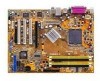
CPU_FAN SiS 656 Intel RC82540EM CHA_FAN PCIEX1_1 PCIEX16 Super I/O PCI1 R PCI2 AD1986A FP_AUDIO CD FLOPPY PCIEX1_2 AUX PCI3 USBPW78 USBPW56 GAME SiS 965L CR2032 3V Lithium Cell CMOS Power SATA1 4Mb BIOS SATA2 USB56 PRI_IDE USB78 SB_PWR CHASSIS CLRTC PANEL SEC_IDE ASUS P5SD2-X 1-7 - Asus P5SD2-X | P5SD2-X English Manual E2026 - Page 20
Unit (CPU) The motherboard comes with a surface mount LGA775 socket designed for the Intel® Pentium® 4 processor in the 775-land package. • Your boxed Intel® Pentium® 4 LGA775 processor package should come with installation instructions for the CPU, fan and heatsink assembly. If the instructions in - Asus P5SD2-X | P5SD2-X English Manual E2026 - Page 21
cap B from the load plate window to remove (B). Load plate 5. Position the CPU over the socket, making sure that the gold triangle is on the bottom-left corner of the socket. The socket alignment key should fit A l i g n m e n t k e y into the CPU notch. Gold triangle mark ASUS P5SD2-X A 1-9 - Asus P5SD2-X | P5SD2-X English Manual E2026 - Page 22
the CPU into the socket to prevent bending the connectors on the socket and damaging the CPU! 6. Close the load plate (A), then A push the load lever (B) until it snaps into the retention tab. B The motherboard supports Intel® Pentium® 4 LGA775 processors with the Intel® Enhanced Memory 64 - Asus P5SD2-X | P5SD2-X English Manual E2026 - Page 23
. To install the CPU heatsink and fan: 1. Place the heatsink on top of the installed CPU, making sure that the four fasteners match the holes on the motherboard. Fastener Motherboard hole Make sure each fastener is oriented as shown, with the narrow groove directed outward. ASUS P5SD2-X 1-11 - Asus P5SD2-X | P5SD2-X English Manual E2026 - Page 24
the fan and heatsink assembly is in place, connect the CPU fan cable to the connector on the motherboard labeled CPU_FAN. P5SD2-X CPU_FAN GND CPU FAN PWR CPU FAN IN CPU FAN PWM ® P5SD2-X CPU fan connector Do not forget to connect the CPU fan connector! Hardware monitoring errors can occur if you - Asus P5SD2-X | P5SD2-X English Manual E2026 - Page 25
1. Disconnect the CPU fan cable from the connector on the motherboard labeled CPU_FAN. 2. Rotate each fastener counterclockwise. 3. Pull up two fasteners at a time in a diagonal sequence to disengage the heatsink B and fan assembly from the A A motherboard. B A B B A ASUS P5SD2-X 1-13 - Asus P5SD2-X | P5SD2-X English Manual E2026 - Page 26
4. Remove the heatsink and fan assembly from the motherboard. 5. Rotate each fastener clockwise to reset the orientation. When reset, each fastener should be oriented as shown, with the narrow groove directed outward. 1-14 Chapter 1: Product introduction - Asus P5SD2-X | P5SD2-X English Manual E2026 - Page 27
Due to chipset limitation, DIMM modules with 128 Mb memory chips or double-sided x16 memory chips are not supported in this motherboard. • Use only qualified DIMMs modules on this motherboard. Visit the ASUS website (www.asus.com) for the latest DDR2 Qualified Vendors List (QVL). ASUS P5SD2-X 1-15 - Asus P5SD2-X | P5SD2-X English Manual E2026 - Page 28
configurations For dual-channel configuration, the total size of memory module(s) installed per channel must be the same to ensure optimum performance. (DDR_A1 + DDR_A2 = DDR_B1 + DDR_B2) Channel Channel A Channel B Sockets DDR_A1 and DDR_A2 DDR_B1 and DDR_B2 1-16 Chapter 1: Product introduction - Asus P5SD2-X | P5SD2-X English Manual E2026 - Page 29
. 1. Simultaneously press the retaining clips outward to unlock the DIMM. Support the DIMM lightly with your fingers when pressing the retaining clips. The DIMM might get damaged when it flips out with extra force. 1 2 1 DDR2 DIMM notch 2. Remove the DIMM from the socket. ASUS P5SD2-X 1-17 - Asus P5SD2-X | P5SD2-X English Manual E2026 - Page 30
slots and the expansion cards that they support. Make sure to unplug the power cord before adding or removing expansion cards. Failure to do so may cause you physical injury and damage motherboard components. 1.8.1 Installing an expansion card To install an expansion card: 1. Before installing the - Asus P5SD2-X | P5SD2-X English Manual E2026 - Page 31
LAN Onboard audio Onboard RAID A shared - - shared shared shared B used C D E - -- - shared - shared used shared - shared - - - -- F used - - - - - G used - - - - H used - - - When using PCI cards on shared slots, ensure that the drivers support "Share IRQ" or that the cards - Asus P5SD2-X | P5SD2-X English Manual E2026 - Page 32
1.8.4 PCI slots The PCI slots support cards such as a LAN card, SCSI card, USB card, and other cards that comply with PCI specifications. The figure shows a LAN card installed on a PCI slot. 1.8.5 PCI Express x16 slot This motherboard supports PCI Express x16 graphic cards that comply with the PCI - Asus P5SD2-X | P5SD2-X English Manual E2026 - Page 33
Clear CMOS You do not need to clear the RTC when the system hangs due to overclocking. For system failure due to overclocking, use the C.P.R. (CPU Parameter Recall) feature. Shut down and reboot the system so the BIOS can automatically reset parameter settings to default values. ASUS P5SD2-X 1-21 - Asus P5SD2-X | P5SD2-X English Manual E2026 - Page 34
to +5VSB to wake up from S3 and S4 sleep modes (no power to CPU, DRAM in slow refresh, power supply in reduced power mode). The USBPWR12 and to additional USB ports. USBPW12 USBPW34 12 23 P5SD2-X +5V (Default) +5VSB USBPW78 USBPW56 ® 12 23 +5V P5SD2-X USB device wake-up (Default) +5VSB - Asus P5SD2-X | P5SD2-X English Manual E2026 - Page 35
table for the function of the audio ports in 2, 4, or 6-channel configuration. Audio 2, 4, or 6-channel configuration Port Light Blue Lime Pink Headset 2-channel Line In Line Out Mic In 4-channel Line In Front Speaker Out Mic In 6-channel Line In Front Speaker Out Mic In ASUS P5SD2-X 1-23 - Asus P5SD2-X | P5SD2-X English Manual E2026 - Page 36
port is for serial devices. 1 0 . C o a x i a l S / P D I F O u t p o r t . This port connects an external audio output device via a coaxial S/PDIF cable. 1 1 . P S / 2 k e y b o a r d p o r t ( p u r p l e to PIN 1. P5SD2-X Floppy disk drive connector P5SD2-X 1-24 Chapter 1: Product introduction - Asus P5SD2-X | P5SD2-X English Manual E2026 - Page 37
has three connectors: a blue connector for the primary IDE connector on the motherboard, a black connector for an Ultra DMA 100/66 IDE slave device ( conductor IDE cable for Ultra DMA 100/66 IDE devices. P5SD2-X SEC_IDE ® P5SD2-X IDE connectors NOTE: Orient the red markings (usually zigzag) - Asus P5SD2-X | P5SD2-X English Manual E2026 - Page 38
or the Windows® XP Service Pack1 before using Serial ATA. 4. CPU and Chassis fan connectors (4-pin CPU_FAN, 3-pin CHA_FAN) The fan connectors support cooling fans of 350mA~2000mA (24W max.) or a total of 1A~3.48A (41.36W max.) at +12V. Connect the fan cables to the fan connectors on the motherboard - Asus P5SD2-X | P5SD2-X English Manual E2026 - Page 39
a chassis-mounted front panel audio I/O module that supports legacy AC '97 audio standard. Connect one end of the front panel audio I/O module cable to this connector. AGND +5VA BLINE_OUT_R BLINE_OUT_L P5SD2-X ® FP_AUDIO P5SD2-X Front panel audio connector ASUS P5SD2-X MIC2 MICPWR Line out_R - Asus P5SD2-X | P5SD2-X English Manual E2026 - Page 40
power is inadequate. • The ATX 12 V Specification 2.0-compliant PSU passed the motherboard power requirement test with the following configuration: CPU : Memory : Graphics card : Parallel ATA devices : Serial ATA device : Optical drives : SCSI devices : Intel® Pentium® 4 3.6 GHz 512 MB - Asus P5SD2-X | P5SD2-X English Manual E2026 - Page 41
you to receive stereo audio input from sound sources such as a CD-ROM, TV-tuner, or MPEG card. P5SD2-X Right Audio Channel Ground Ground Left Audio Channel Right Audio Channel Ground Ground Left Audio Channel ® CD(Black) AUX(White) P5SD2-X Internal audio connectors 9 . Chassis intrusion connector - Asus P5SD2-X | P5SD2-X English Manual E2026 - Page 42
supports several chassis-mounted functions. PLED SPEAKER PLED+ PLED+5V Ground Ground Speaker P5SD2-X PANEL IDE_LED+ IDE_LED- PWR Ground Reset Ground ® IDE_LED RESET PWRSW P5SD2-X System Panel connector * Requires an ATX SOFT-OFF mode depending on the BIOS settings. Pressing the power switch - Asus P5SD2-X | P5SD2-X English Manual E2026 - Page 43
This chapter tells how to change the system settings through the BIOS Setup menus. Detailed descriptions of the BIOS parameters are also provided. 2 BIOS setup ASUS P5SD2-X 2-1 - Asus P5SD2-X | P5SD2-X English Manual E2026 - Page 44
motherboard BIOS using the ASUS Update or AFUDOS utilities. 2.1.1 Creating a bootable floppy disk 1. Do either one of the following to create a bootable floppy disk. DOS environment a. Insert a 1.44MB floppy disk into the drive. b. At the DOS prompt, type format A:/S then press . Windows® XP - Asus P5SD2-X | P5SD2-X English Manual E2026 - Page 45
your optical drive. e. Press , then follow screen instructions to continue. 2. Copy the original or the latest motherboard BIOS file to the bootable floppy disk. 2.1.2 ASUS EZ Flash utility The ASUS EZ Flash feature allows you to update the BIOS without having to go through the long process - Asus P5SD2-X | P5SD2-X English Manual E2026 - Page 46
-protected and has at least 600 KB free space to save the file. • The succeeding BIOS screens are for reference only. The actual BIOS screen displays may not be exactly the same as shown. 1. Copy the AFUDOS utility (afudos.exe) from the motherboard support CD to the bootable floppy disk you created - Asus P5SD2-X | P5SD2-X English Manual E2026 - Page 47
Updating the BIOS file To update the BIOS file using the AFUDOS utility: 1. Visit the ASUS website (www.asus.com) and download the latest BIOS file for the motherboard. Save the BIOS file to a bootable floppy disk. Write the BIOS filename on a piece of paper. You need to type the exact BIOS filename - Asus P5SD2-X | P5SD2-X English Manual E2026 - Page 48
2 utility The ASUS CrashFree BIOS 2 is an auto recovery tool that allows you to restore the BIOS file when it fails or gets corrupted during the updating process. You can update a corrupted BIOS file using the motherboard support CD or the floppy disk that contains the updated BIOS file. • Prepare - Asus P5SD2-X | P5SD2-X English Manual E2026 - Page 49
while updating the BIOS! Doing so can cause system boot failure! 4. Restart the system after the utility completes the updating process. The recovered BIOS may not be the latest BIOS version for this motherboard. Visit the ASUS website (www.asus.com) to download the latest BIOS file. ASUS P5SD2 - Asus P5SD2-X | P5SD2-X English Manual E2026 - Page 50
you to manage, save, and update the motherboard BIOS in Windows® environment. The ASUS Update utility allows you to: • Save the current BIOS file • Download the latest BIOS file from the Internet • Update the BIOS from an updated BIOS file • Update the BIOS directly from the Internet, and • View - Asus P5SD2-X | P5SD2-X English Manual E2026 - Page 51
U p d a t e. The ASUS Update main window appears. 2. Select U p d a t e B I O S f r o m 3. Select the ASUS FTP site t h e I n t e r n e t option from the nearest you to avoid network drop-down menu, then click traffic, or click A u t o S e l e c t. N e x t. Click N e x t. ASUS P5SD2-X 2-9 - Asus P5SD2-X | P5SD2-X English Manual E2026 - Page 52
to download. Click Next. 5. Follow the screen instructions to complete the update process. The ASUS Update utility is capable of updating itself through the Internet. Always update the utility to avail all its features. Updating the BIOS through a BIOS file To update the BIOS through a BIOS file - Asus P5SD2-X | P5SD2-X English Manual E2026 - Page 53
under the Exit Menu. See section "2.7 Exit Menu." • The BIOS setup screens shown in this section are for reference purposes only, and may not exactly match what you see on your screen. • Visit the ASUS website (www.asus.com) to download the latest BIOS file for this motherboard. ASUS P5SD2-X 2-11 - Asus P5SD2-X | P5SD2-X English Manual E2026 - Page 54
2.2.1 BIOS menu screen Menu items Menu bar Configuration fields General help System Time System Date Legacy Diskette A [11:51:19] [Thu 05/07/2004] [1.44M, select items in the menu and change the settings. Some of the navigation keys differ from one screen to another. 2-12 Chapter 2: BIOS setup - Asus P5SD2-X | P5SD2-X English Manual E2026 - Page 55
of the menu screen is a brief description of the selected item. Advanced Chipset settings WARNING: Setting wrong values in the sections below may cause system to malfunction. Configure DRAM Timing +- Change Option F1 General Help F10 Save and Exit ESC Exit Pop-up window Scroll bar ASUS P5SD2-X 2-13 - Asus P5SD2-X | P5SD2-X English Manual E2026 - Page 56
screen appears, giving you an overview of the basic system information. Refer to section "2.2.1 BIOS menu screen" for information on the menu screen items and how to navigate through them. 25 in.] [1.2M , 5.25 in.] [720K , 3.5 in.] [1.44M, 3.5 in.] [2.88M, 3.5 in.] 2-14 Chapter 2: BIOS setup - Asus P5SD2-X | P5SD2-X English Manual E2026 - Page 57
and Fourth IDE Master While entering Setup, the BIOS automatically detects the presence of IDE devices. There is supports multi-sector transfer feature. When set to [Disabled], the data transfer from and to the device occurs one sector at a time. Configuration options: [Disabled] [Auto] ASUS P5SD2 - Asus P5SD2-X | P5SD2-X English Manual E2026 - Page 58
] 32Bit Data Transfer [Disabled] Enables or disables 32-bit data transfer. Configuration options: [Disabled] [Enabled] 2.3.5 OnBoard PCI S-ATA Controller [Native] Disables or sets the onboard PCI Serial ATA controller. Configuration options: [Disabled] [Native] [RAID] 2-16 Chapter 2: BIOS setup - Asus P5SD2-X | P5SD2-X English Manual E2026 - Page 59
: 09/23/05 Processor Type Speed Count : Genuine Intel(R) CPU 3.20GHz : 3800 MHz : 1 System Memory Size : 256MB AMI BIOS Displays the auto-detected BIOS information Processor Displays the auto-detected CPU specification System Memory Displays the auto-detected system memory ASUS P5SD2-X 2-17 - Asus P5SD2-X | P5SD2-X English Manual E2026 - Page 60
cause the system to malfunction. JumperFree Configuration CPU Configuration Chipset Onboard Devices Configuration PCI PnP USB Configuration system. O v e r c l o c k P r o f i l e - loads overclocking profiles with optimal parameters for stability when overclocking. 2-18 Chapter 2: BIOS setup - Asus P5SD2-X | P5SD2-X English Manual E2026 - Page 61
only when the AI Overclocking item is set to [Manual]. Auto Detect CPU Frequency [Enabled] Enables or disables the CPU frequency auto-detect feature. Configuration options: [Disabled] [ options. Configuration options: [Overclock 5%] [Overclock 10%] [Overclock 15%] [Overclock 20%] ASUS P5SD2-X 2-19 - Asus P5SD2-X | P5SD2-X English Manual E2026 - Page 62
show the CPU-related information that the BIOS automatically detects. Configure Advanced CPU settings Manufacturer: Intel Brand String: Genuine Intel(R) CPU 2.80GHz Frequency ], the BIOS will automatically check the CPU's capability to enable the C1E support. In C1E mode, the CPU power consumption - Asus P5SD2-X | P5SD2-X English Manual E2026 - Page 63
want to use EIST. Configuration options: [Disabled] [Enabled] 2.4.3 Chipset The Chipset menu allows you to change the advanced chipset settings. Select an item then press to display the sub-menu. NorthBridge SIS656 Configuration SouthBridge SIS965/SIS965L Configuration ASUS P5SD2-X 2-21 - Asus P5SD2-X | P5SD2-X English Manual E2026 - Page 64
SIS656 Configuration The items in this sub-menu show the SIS 656 NorthBridge related configuration. Primary Graphics Adapter CPU FSB Set To Chipset Timing DRAM CAS# Latency 128 Bit related configuration. OnBoard AC97 Audio DEVICE [Enabled] OnBoard AC97 Audio DEVICE [Enabled] Enables or - Asus P5SD2-X | P5SD2-X English Manual E2026 - Page 65
Chipset Onboard LAN Onboard LAN Boot ROM Serial Port1 Address Parallel Port Address Parallel Port Mode ECP Mode DMA Channel Parallel Port IRQ Onboard Game/MIDI Port [Enabled] [Disabled] [3F8/IRQ4] [378] [ECP] [DMA3] [IRQ7] [Disabled] Enable or Disable High Definition Audio Controller OnBoard LAN - Asus P5SD2-X | P5SD2-X English Manual E2026 - Page 66
ISA devices, and setting the memory size block for legacy ISA card if the card requests for an IRQ. When set to [No], BIOS does not assign an IRQ to the PCI VGA card even if requested. Configuration options: [No] [Yes] IRQ-xx assigned to [PCI Device] When set to [PCI Device], the specific IRQ is free - Asus P5SD2-X | P5SD2-X English Manual E2026 - Page 67
device is detected, the legacy USB support is disabled. Configuration options: [Disabled] [Enabled] [Auto] USB 2.0 Controller Mode [HiSpeed] Allows you to set the USB 2.0 controller mode to HiSpeed (480 Mbps) or FullSpeed (12 Mbps). Configuration options: [FullSpeed] [HiSpeed] ASUS P5SD2-X 2-25 - Asus P5SD2-X | P5SD2-X English Manual E2026 - Page 68
S3 Resume ACPI 2.0 Support ACPI APIC Support APM Configuration Hardware Monitor [Auto] [No] [Yes] [Enabled] Configure CPU. Select Screen Select Item No] Determines whether to invoke VGA BIOS POST on S3/STR resume. Configuration options: [No] [Yes] 2.5.3 ACPI 2.0 Support [Yes] Allows you to add more - Asus P5SD2-X | P5SD2-X English Manual E2026 - Page 69
[Enabled] Power On By PCI Devices [Disabled] When set to [Enabled], this parameter allows you to turn on the system through a PCI LAN or modem card. This feature requires an ATX power supply that provides at least 1A on the +5VSB lead. Configuration options: [Disabled] [Enabled] ASUS P5SD2-X 2-27 - Asus P5SD2-X | P5SD2-X English Manual E2026 - Page 70
Alarm Second [30] Sets the RTC alarm second. Use the plus (+) or minus (-) keys to adjust the values. Configuration options: [00] [01] ~ [59] 2-28 Chapter 2: BIOS setup - Asus P5SD2-X | P5SD2-X English Manual E2026 - Page 71
operating a low CPU temperature. Select a higher ratio if you installed additional devices and the system requires more ventilation. This item appears only when the CPU Q-Fan Control item is Enabled. Configuration options: [Auto] [90%] [80%] [70%] [60%] [50%] [40%] [30%] [20%] ASUS P5SD2-X 2-29 - Asus P5SD2-X | P5SD2-X English Manual E2026 - Page 72
the CPU temperature threshold when the CPU fan speed is increased to lower the CPU temperature. This item appears only when the CPU Q-Fan Control item is Enabled. The configuration options vary depending on the CPU installed. F1 General Help F10 Save and Exit ESC Exit 2-30 Chapter 2: BIOS setup - Asus P5SD2-X | P5SD2-X English Manual E2026 - Page 73
], BIOS performs all the POST items. Configuration options: [Disabled] [Enabled] Full Screen Logo [Enabled] This allows you to enable or disable the full screen logo display feature. Configuration options: [Disabled] [Enabled] Set this item to [Enabled] to use the ASUS MyLogo™ feature. ASUS P5SD2 - Asus P5SD2-X | P5SD2-X English Manual E2026 - Page 74
options: [Disabled] [Enabled] Interrupt 19 Capture [Disabled] When set to [Enabled], this function allows the option ROMs to trap Interrupt 19. Configuration options: [Disabled] [Enabled] 2-32 Chapter 2: BIOS setup - Asus P5SD2-X | P5SD2-X English Manual E2026 - Page 75
, select the Change Supervisor Password then press . The message "Password Uninstalled" appears. If you forget your BIOS password, you can clear clear it by erasing the CMOS Real Time Clock (RTC) RAM. See section "1.9 Jumpers" for information on how to erase the RTC RAM. ASUS P5SD2-X 2-33 - Asus P5SD2-X | P5SD2-X English Manual E2026 - Page 76
the user password, follow the same steps as in setting a user password. Clear User Password Select this item to clear the user password. 2-34 Chapter 2: BIOS setup - Asus P5SD2-X | P5SD2-X English Manual E2026 - Page 77
confirmation window appears. Select O k to save changes and exit. If you attempt to exit the Setup program without saving your changes, the program prompts you with a message asking if you want to save your changes before exiting. Press to save the changes while exiting. ASUS P5SD2-X 2-35 - Asus P5SD2-X | P5SD2-X English Manual E2026 - Page 78
fields other than System Date, System Time, and Password, the BIOS asks for a confirmation before exiting. Discard Changes This option on the Setup menus. When you select this option or if you press , a confirmation window appears. Select O k to load default values. Select E x i t & S a v - Asus P5SD2-X | P5SD2-X English Manual E2026 - Page 79
This chapter describes the contents of the support CD that comes with the motherboard package. 3 Software support ASUS P5SD2-X 3-1 - Asus P5SD2-X | P5SD2-X English Manual E2026 - Page 80
that you install Windows® 2000 Service Pack 4 or the Windows® XP Service Pack 2 or later versions before installing the drivers for better compatibility and system stability. 3.2 Support CD information The support CD that came with the motherboard package contains the drivers, software applications - Asus P5SD2-X | P5SD2-X English Manual E2026 - Page 81
motherboard. SiS RAID Controller Driver Installs the SiS RAID controller driver. SoundMAX ADI1986A Audio Driver Installs the SoundMAX ADI1986A audio driver and application. Intel Gigabit Ethernet Driver Installs the Intel® Gigabit LAN driver. USB 2.0 Driver Installs the USB 2.0 driver. ASUS P5SD2 - Asus P5SD2-X | P5SD2-X English Manual E2026 - Page 82
monitors the fan speed, CPU temperature, and system voltages, and alerts you of any detected problems. This utility helps you keep your computer in healthy operating condition. ASUS Update The ASUS Update utility allows you to update the motherboard BIOS in a Windows® environment. This utility - Asus P5SD2-X | P5SD2-X English Manual E2026 - Page 83
removes computer viruses. View the online help for detailed information. 3.2.4 Make Disk menu The Make Disk menu shows the applications and other software that the motherboard supports. Make SiS RAID Controller Driver Disk Allows you to create a SiS RAID controller driver disk. ASUS P5SD2-X 3-5 - Asus P5SD2-X | P5SD2-X English Manual E2026 - Page 84
SATA RAID User's Manual Allows you to open the SIS 965/965L SATA RAID user's manual. 3.2.6 ASUS Contact information Click the C o n t a c t tab to display the ASUS contact information. You can also find this information on the inside front cover of this user guide. 3-6 Chapter 3: Software support
-
 1
1 -
 2
2 -
 3
3 -
 4
4 -
 5
5 -
 6
6 -
 7
7 -
8
-
9
-
10
-
11
-
12
-
13
-
14
-
15
-
16
-
17
-
18
-
19
-
20
-
21
-
22
-
23
-
24
-
25
-
26
-
27
-
28
-
29
-
30
-
31
-
32
-
33
-
34
-
35
-
36
-
37
-
38
-
39
-
40
-
41
-
42
-
43
-
44
-
45
-
46
-
47
-
48
-
49
-
50
-
51
-
52
-
53
-
54
-
55
-
56
-
57
-
58
-
59
-
60
-
61
-
62
-
63
-
64
-
65
-
66
-
67
-
68
-
69
-
70
-
71
-
72
-
73
-
74
-
75
-
76
-
77
-
78
-
79
-
80
-
81
-
82
-
83
-
84
 |
 |

Motherboard
P5SD2-X