Asus P7F-E User Manual
Asus P7F-E - Motherboard - ATX Manual
 |
UPC - 610839172924
View all Asus P7F-E manuals
Add to My Manuals
Save this manual to your list of manuals |
Asus P7F-E manual content summary:
- Asus P7F-E | User Manual - Page 1
P7F-E Motherboard - Asus P7F-E | User Manual - Page 2
without the express written permission of ASUSTeK COMPUTER INC. ("ASUS"). Product warranty or service will not be extended if: ASUS HAS BEEN ADVISED OF THE POSSIBILITY OF SUCH DAMAGES ARISING FROM ANY DEFECT OR ERROR IN THIS MANUAL OR PRODUCT. SPECIFICATIONS AND INFORMATION CONTAINED IN THIS MANUAL - Asus P7F-E | User Manual - Page 3
viii About this guide ix Typography x P7F-E specifications summary xi Chapter 1: Product introduction 1.1 Welcome 1-3 1.2 Package contents 1-3 1.3 Serial number label 1-4 1.4 Special features 1-4 1.4.1 Product highlights 1-4 1.4.2 Innovative ASUS features 1-6 Chapter 2: Hardware - Asus P7F-E | User Manual - Page 4
x16 slot (x16 link 2-18 2.5.7 PCI Express x1 slot 2-19 2.5.8 PCI slots 2-19 2.5.9 PIKE slot 2-19 2.5.10 Installing an ASUS PIKE RAID card 2-20 2.5.11 Installing i Button 2-21 2.5.12 Installing ASMB4 management board 2-21 2.5.13 Connect Thermal sensor cable 2-22 2.5.14 Installing the audio - Asus P7F-E | User Manual - Page 5
4-25 4.4.7 Event Log Configuration 4-27 4.4.8 Intel VT-d Configuration [Disabled 4-27 4.4.9 SR-IOV Supprted [Disabled 4-27 4.5 Server menu 4-28 4.5.1 Remote Access Configuration 4-28 4.6 Power menu 4-30 4.6.1 ACPI APIC Support [Enabled 4-30 4.6.2 APM Configuration 4-30 4.6.3 Hardware Monitor - Asus P7F-E | User Manual - Page 6
in the BIOS Setup Utility 5-34 Chapter 6: Driver installation 6.1 RAID driver installation 6-3 6.1.1 Creating a RAID driver disk 6-3 6.1.2 Installing the RAID controller driver 6-6 6.2 Intel® chipset device installation 6-19 6.3 LAN driver installation 6-21 6.4 VGA driver installation 6-24 - Asus P7F-E | User Manual - Page 7
and used in accordance with manufacturer' s instructions, may cause harmful interference to radio communications. cables for connection of the monitor to the graphics card is required to assure compliance with FCC regulations. ASUS REACH website at http://green.asus.com/english/REACH.htm. vii - Asus P7F-E | User Manual - Page 8
qualified service technician or your retailer. Operation safety • Before installing the motherboard and adding devices on it, carefully read all the manuals stable surface. • If you encounter technical problems with the product, contact a qualified service technician or your retailer. This symbol of - Asus P7F-E | User Manual - Page 9
Detailed descriptions of the BIOS parameters are also provided. • Chapter 5: RAID configuration This chapter provides instructions for setting up, creating, and configuring RAID sets using the available utilities. • Chapter 6: Driver installation This chapter provides instructions for installing the - Asus P7F-E | User Manual - Page 10
the following symbols used throughout this manual. DANGER/WARNING: Information to prevent injury to yourself when trying to complete a task. CAUTION: Information to prevent damage to the components when trying to complete a task. IMPORTANT: Instructions that you MUST follow to complete - Asus P7F-E | User Manual - Page 11
Support / System Bus 1 * Socket LGA1156 Quad Core Intel Xeon 3400 series Server Processor Quad Core Intel Core i7-800 series Desktop Processor Quad Core Intel Core i5-700 series Desktop Processor Dual Core 32nm CPU design Ready Core Logic Intel® 3420 PCH Form Factor ATX, 12" * 9.6" ASUS - Asus P7F-E | User Manual - Page 12
RPM Intel® 3420: 6* SATA2 300MB/s portsIntel Matrix Storage utility supports software RAID 0, 1, 10 & 5 (Windows) LSI MegaRAID driver supports software RAID 0, 1& 10 (Windows & Linux) Optional: ASUS PIKE 1064E 4-port SAS card (Support FW RAID 0,1,1E) ASUS PIKE 1068E 8-port SAS card (support FW RAID - Asus P7F-E | User Manual - Page 13
This chapter describes the motherboard introPdruoc1dtuiocnt features and the new technologies it supports. - Asus P7F-E | User Manual - Page 14
Chapter summary 1 1.1 Welcome 1-3 1.2 Package contents 1-3 1.3 Serial number label 1-4 1.4 Special features 1-4 ASUS P7F-E - Asus P7F-E | User Manual - Page 15
SAS card Support integrated H/W RAID 0, 1, 10, 5, 50, 6, and 60 ASUS PIKE 6480 8-port SAS card Support FW RAID 0, 1, 10 and 5 ASMB4-iKVM Remote Management solution provides KVM over IP solution. ASUS MIO audio card Discrete 8 channel audio card provides clearest high quality sounds ASUS P7F - Asus P7F-E | User Manual - Page 16
and satisfying solution to your problems. P7F-E xxS2xxxxxxxxx Made in China 合格 1.4 Special features 1.4.1 Product highlights Intel® LGA1156 Xeon 3400 Processor Ready This motherboard supports the latest Intel® Xeon 3400 processors in LGA1156 package, which has memory and PCI Express controller - Asus P7F-E | User Manual - Page 17
loading and system speed or power requirement. Serial ATA II technology The motherboard supports the Serial ATA II 3 Gb/s technology through the Serial ATA interface and Intel 3420 chipset. The Serial ATA II specification provides twice the bandwidth of the current Serial ATA products with a host - Asus P7F-E | User Manual - Page 18
automatically when the Slot 3 is not occupied. With this flexibility, ASUS Flex-E makes motherboards suitable for both Server and Workstation. ASUS MIO Audio card Enjoy high-end sound quality! The ASUS MIO audio card is a discrete 8-channel high definition audio (High Definition Audio previously - Asus P7F-E | User Manual - Page 19
This chapter lists the hardware setup procedures that you have to perform when installing system components. It includes description of the jumpers and connectors on the motherboard. 2 Hardware information - Asus P7F-E | User Manual - Page 20
Chapter summary 2 2.1 Before you proceed 2-3 2.2 Motherboard overview 2-5 2.3 Central Processing Unit (CPU 2-9 2.4 System memory 2-15 2.5 Expansion slots 2-17 2.6 Jumpers 2-23 2.7 Connectors 2-27 ASUS P7F-E - Asus P7F-E | User Manual - Page 21
in soft-off mode. This is a reminder that you should shut down the system and unplug the power cable before removing or plugging in any motherboard component. The illustration below shows the location of the onboard LED ASUS P7F-E 2-3 - Asus P7F-E | User Manual - Page 22
BMC_LED1) The green heartbeat LED blinks per second to indicate that the ASMB4 is working normally. • The heartbeat LED functions only when you install the ASUS ASMB4. • Everytime afte rthe AC power is replugged, you have to wait for about 30 seconds for the system power up 2-4 Chapter 2: Hardware - Asus P7F-E | User Manual - Page 23
of the chassis as indicated in the image below. 2.2.2 Screw holes Place nine (9) screws into the holes indicated by circles to secure the motherboard to the chassis. DO NOT overtighten the screws! Doing so can damage the motherboard. Place this side towards the rear of the chassis ASUS P7F-E 2-5 - Asus P7F-E | User Manual - Page 24
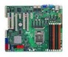
2.2.3 Motherboard layout 2-6 Chapter 2: Hardware information - Asus P7F-E | User Manual - Page 25
Chassis Fan control setting (3-pin CPUFAN_SEL1, CHAFAN_SEL1) 4. LAN controller setting (3-pin LAN_SW1, LAN_SW2) 5. iBTN RAID setting (3-pin IBTN_SEL1) 6. RAID configuration utility selection (3-pin RAID_SEL1) 7. Force BIOS 26 2-26 Page 2-27 2-27 2-27 2-27 2-27 2-27 2-27 2-27 ASUS P7F-E 2-7 - Asus P7F-E | User Manual - Page 26
SATA1, SATA2, SATA3, SATA4; RED) (7-pin SATA5, SATA6; Black) 2. SAS connectors (7-pin SAS1, SAS2, SAS3, SAS4; Red) (7-pin SAS5, SAS6, header (BMC_FW1) 11. Power Supply SMBus connector (5-pin PSUSMB1) 12. ATX power connectors (24-pin EATXPWR1, 8-pin EATX12V1) 13. System panel connector - Asus P7F-E | User Manual - Page 27
The motherboard comes with a surface mount LGA1156 socket designed for the Intel® Xeon 3400 series Processors. • Upon purchase of the motherboard, ensure the motherboard. ASUS will process Return Merchandise Authorization (RMA) requests only if the motherboard comes with the cap on the LGA1156 - Asus P7F-E | User Manual - Page 28
3. Lift the load lever in the direction of the arrow until the load plate is completely lifted. Load plate 4. Remove the PnP cap from the CPU socket. PnP cap 5. Position the CPU over the socket, ensuring that the gold triangle is on the bottom‑left corner of the socket, and then fit the socket - Asus P7F-E | User Manual - Page 29
the load lever (B), ensuring that the front edge of the load plate slides under the retention knob (C). B A C 8. Insert the load lever under the retention tab. ASUS P7F-E 2-11 - Asus P7F-E | User Manual - Page 30
Intel®‑certified multi‑directional heatsink and fan. • Your Intel® LGA1156 heatsink and fan assembly comes in a push-pin design and requires no tool to install. • Use an LGA1156-compatible CPU heatsink and fan assembly only. The LGA1156 have installed the motherboard to the chassis before you install - Asus P7F-E | User Manual - Page 31
on the motherboard. 2. Rotate each fastener counterclockwise. 3. Pull up two fasteners at a time in a diagonal sequence to disengage the heatsink and fan assembly from the motherboard. A B A B A B A 4. Carefully remove the heatsink and fan assembly from the motherboard. ASUS P7F-E 2-13 - Asus P7F-E | User Manual - Page 32
2.3.2 Installing the CPU heatsink in rack The Intel® 1156 processors require a specially designed heatsink to ensure the sticker on the heatsink metal plate and affix the plate to the back of the motherboard, matching the standoffs to the heatsink screw holes. 2. Use a Phillips screwdriver to - Asus P7F-E | User Manual - Page 33
DIMMs into the DIMM sockets using the memory configurations in this section. RDIMM* DIMM Slot compatibility, it is recommended that you obtain memory modules from the same vendor. DO NOT combine RDIMM and UDIMM. • The motherboard supports x8 DRAM Only and x4 & x16 DRAM are not supported ASUS P7F - Asus P7F-E | User Manual - Page 34
system components. Failure to do so can cause severe damage to both the motherboard and the components. To install a DIMM: 2 1. Press the retaining into a socket to avoid damaging the DIMM. • The DDR3 DIMM sockets do not support DDR and DDR2 DIMMs. DO NOT install DDR or DDR2 DIMMs to the DDR3 DIMM - Asus P7F-E | User Manual - Page 35
software drivers for the expansion card. When using PCI cards on shared slots, ensure that the drivers support "Share IRQ" or that the cards do not need IRQ assignments. Otherwise, conflicts will arise between the two PCI groups, making the system unstable and the card inoperable. ASUS P7F-E 2-17 - Asus P7F-E | User Manual - Page 36
PCI Steering 11* 6 IRQ Holder for PCI Steering 12* 7 PS/2 Compatible Mouse Port 13 8 Numeric Data Processor 14* 9 Primary IDE Channel provides one x8 link to CPU. This slot supports VGA cards and various server class high performance add-on cards. 2.5.6 PCI Express x16 slot (x16 link) - Asus P7F-E | User Manual - Page 37
. 2.5.8 PCI slots The PCI slot supports cards such as a LAN card, USB card, and other cards that comply with PCI 2.3 specifications. 2.5.9 PIKE slot The PIKE slot allows you to choose and change your preferred SAS solution easily. Install an optional ASUS PIKE RAID card based on your needs. MIO PCIE - Asus P7F-E | User Manual - Page 38
the steps below to install an optional ASUS RAID card on your motherboard. 1. Locate the PIKE RAID card slot on the motherboard. 2. Align the golden fingers of the RAID card with the PIKE RAID card slot. 3. Insert the RAID card into the PIKE RAID card slot. Ensure that it is completely seated - Asus P7F-E | User Manual - Page 39
I Button before using PIKE 1078 functions. 2.5.12 Installing ASMB4 management board Follow the steps below to install an optional ASMB4 management board on your motherboard. 1. Locate the BMC_FW1 header on the motherboard. 2. Orient and press the ASMB4 management card in place. ASUS P7F-E 2-21 - Asus P7F-E | User Manual - Page 40
would like to monitor temperature. 2.5.14 Installing the audio card 1. Locate the audio slot on the motherboard. 2. Align the card connector with the slot and press firmly until the card sits on the slot completely. This slot does not support PCI-E x1 cards. 2-22 Chapter 2: Hardware information - Asus P7F-E | User Manual - Page 41
the RTC RAM, never remove the cap on CLRTC jumper default position. Removing the cap will cause system boot failure! If the steps above do not help, remove the onboard battery and move the jumper again to clear the CMOS RTC RAM data. After the CMOS clearance, reinstall the battery. ASUS P7F-E 2-23 - Asus P7F-E | User Manual - Page 42
) This jumper allows you to enable or disable the onboard VGA controller. Set to pins 1-2 to activate the VGA feature. 3. CPU Fan and Chassis Fan control setting (3-pin CPUFAN_SEL1, CHAFAN_SEL1) These jumpers allow you to switch for fan pin selection. The CPUFAN_SEL1 jumper is for the CPU fan - Asus P7F-E | User Manual - Page 43
5. iBTN RAID setting (3-pin IBTN_SEL1) This jumper allows you to select the RAID configuration utility to use when you create disk arrays. Place the jumper caps on pins 1-2 if you install a PIKE RAID card to the motherboard and want to use the LSI Logic MPT Setup Utility (default). ASUS P7F-E 2-25 - Asus P7F-E | User Manual - Page 44
the RAID configuration utility to use when you create disk arrays. Place the jumper caps over pins 1-2 if you want to use the LSI Logic Embedded SATA RAID Setup Utility (default); otherwise, place the jumper caps to pins 2-3 to use the Intel® Matrix Storage Manager. 7. Force BIOS recovery setting - Asus P7F-E | User Manual - Page 45
port is for a PS/2 mouse. 2. RJ-45 port for iKVM. This RJ-45 port functions only when you install ASMB4 management card. 3. PS/2 keyboard port (purple). This port is for a PS/2 keyboard. 4. USB 2.0 ports 1 and 2. These two GREEN 1 Gbps connection ACT/LINK SPEED LED LED LAN port ASUS P7F-E 2-27 - Asus P7F-E | User Manual - Page 46
; Black) Supported by the Intel® 3420 chipset, these connectors are for the Serial ATA signal cables for Serial ATA hard disk drives that allows up to 3Gb/s of data transfer rate. If you installed Serial ATA hard disk drives, you can create a RAID 0, RAID 1, RAID 10, or RAID 5 configuration. • The - Asus P7F-E | User Manual - Page 47
) This motherboard comes with eight (8) Serial Attached SCSI (SAS) connectors, the next-generation storage technology that supports both Serial Attached SCSI (SAS) and Serial ATA (SATA). Each connector supports one device. • These connectors function only when you install a PIKE RAID card. • Connect - Asus P7F-E | User Manual - Page 48
cables to connectors USB34 and USB56, then install the modules to a slot opening at the back of the system chassis. These USB connectors comply with USB 2.0 specification that supports up to 480 Mbps connection speed. 5. Thermal sensor cable connectors (3-pin TR1) This connector is for temperature - Asus P7F-E | User Manual - Page 49
. • DO NOT forget to connect the fan cables to the fan connectors. Insufficient air flow inside the system may damage the motherboard components. • These are not jumpers! DO NOT place jumper caps on the fan connectors! • All fans feature the ASUS Fan Speed Control technology. ASUS P7F-E 2-31 - Asus P7F-E | User Manual - Page 50
) This connector is used for the SGPIO peripherals for the LSI MegaRAID and Intel Matrix RAID SATA LED. 8. Serial General Purpose Input/Output connectors (8-1 pin SGPIO2/3) These connector is used for the SAS chip SGPIO interface that controls the LED pattern generation, device information and - Asus P7F-E | User Manual - Page 51
a serial (COM) port. Connect the serial port module cable to this connector, then install the module to a slot opening at the back of the system chassis. 10. BMC header (BMC_FW1) The BMC connector on the motherboard supports an ASUS® Server Management Board 4 Series (ASMB4). ASUS P7F-E 2-33 - Asus P7F-E | User Manual - Page 52
SMBus interface. 12. ATX power connectors (24-pin EATXPWR1, 8-pin EATX12V1) These connectors are for an ATX power supply plugs. when configuring a system with more power-consuming devices. The system may become unstable or may not boot up if the power is inadequate. • This motherboard supports ATX2 - Asus P7F-E | User Manual - Page 53
HDD. 5. ATX power button/soft BIOS settings. Pressing the power switch for more than four seconds while the system is ON turns the system OFF. 6. Reset button (2-pin RESET) This 2-pin connector is for the chassis-mounted reset button for system reboot without turning off the system power. ASUS P7F - Asus P7F-E | User Manual - Page 54
14. Auxiliary panel connector (20-pin AUX_PANEL1) This connector is for additional front panel features including front panel SMB, locator LED and switch, chassis intrusion, and LAN LEDs. 1. Front panel SMB (6-1 pin FPSMB) These leads connect the front panel SMBus cable. 2. LAN activity LED (2-pin - Asus P7F-E | User Manual - Page 55
This chapter describes the power up Powerin3g up sequence, and ways of shutting down the system. - Asus P7F-E | User Manual - Page 56
Chapter summary 3 3.1 Starting up for the first time 3-3 3.2 Turning off the computer 3-4 ASUS P7F-E - Asus P7F-E | User Manual - Page 57
switches are off. 3. Connect the power cord to the power connector at the back of the system chassis. 4. Connect the power cord to a power outlet that is equipped with a surge protector. 5. Turn hold down the key to enter the BIOS Setup. Follow the instructions in Chapter 4. ASUS P7F-E 3-3 - Asus P7F-E | User Manual - Page 58
computer 3.2.1 Using the OS shut down function If you are using Windows® 2003 Server: 1. Click the Start button then click Shut Down. 2. Select Shut Down to sleep mode or to soft-off mode, depending on the BIOS setting. Pressing the power switch for more than four seconds lets the system enter the - Asus P7F-E | User Manual - Page 59
This chapter tells how to change the system settings through the BIOS Setup BIOS se4tup menus. Detailed descriptions of the BIOS parameters are also provided. - Asus P7F-E | User Manual - Page 60
Chapter summary 4 4.1 Managing and updating your BIOS 4-1 4.2 BIOS setup program 4-7 4.3 Main menu 4-10 4.4 Advanced menu 4-16 4.5 Server menu 4-28 4.6 Power menu 4-30 4.7 Boot menu 4-33 4.8 Tools menu 4-37 4.9 Exit menu 4-38 ASUS P7F-E - Asus P7F-E | User Manual - Page 61
2 BIOS ROM Utility V3.34 FLASH TYPE: MXIC 25L1605A Current ROM BOARD: P7F-E VER: 0205 DATE: 07/23/2009 Update ROM BOARD: Unknown VER: Unknown DATE: Unknown PATH: A:\ A: Note [Enter] Select or Load [Up/Down/Home/End] Move [Tab] Switch [B] Backup [V] Drive Info [Esc] Exit ASUS P7F-E 4-3 - Asus P7F-E | User Manual - Page 62
BUPDATER utility: 1. Visit the ASUS website at www.asus.com and download the latest BIOS file for the motherboard. Save the BIOS file to a bootable�U��S��B��fl�a�s�h��d�i�s�k��d�r�iv��e��. 2. Copy the BUPDATER utility (BUPDATER.exe) from the ASUS support website at support.asus.com to the bootable - Asus P7F-E | User Manual - Page 63
The utility verifies the file, then starts updating the BIOS file. ASUSTek BIOS Update for DOS V1.06 (09/08/04) FLASH TYPE: MXIC 25L1605A Current ROM BOARD: P7F-E VER: 0205 DATE: 07/23/2009 Update ROM BOARD: P7F-E VER: 0206 DATE: 08/10/2009 PATH: WARNING! Do not turn off power during flash - Asus P7F-E | User Manual - Page 64
. It resets the system when the BIOS recovery finished. DO NOT shut down or reset the system while recovering the BIOS! Doing so would cause system boot failure! The recovered BIOS may not be the latest BIOS version for this motherboard. Visit the ASUS website at www.asus.com to download the latest - Asus P7F-E | User Manual - Page 65
the reset button on the system chassis. You can also restart by BIOS setup screens shown in this section are for reference purposes only, and may not exactly match what you see on your screen. • Visit the ASUS website (www.asus.com) to download the latest BIOS file for this motherboard. ASUS P7F - Asus P7F-E | User Manual - Page 66
screen Menu items Menu bar Configuration fields General help Main Advanced BIOS SETUP UTILITY Server Power Boot Tools Exit System Time [13:44:30] System Date [Wed, 08/05/2009] SATA 1 SATA 2 SATA 3 SATA 4 SATA 5 SATA 6 : [ST3160812AS] : [Not Detected] : [Not - Asus P7F-E | User Manual - Page 67
displays the specific then press to display a pop-up window with the configuration options for that item. display the other items on the screen. 4.2.9 General help Pop-up window Scroll bar At the top right corner of the menu screen is a brief description of the selected item. ASUS P7F - Asus P7F-E | User Manual - Page 68
information on the menu screen items and how to navigate through them. Main Advanced BIOS SETUP UTILITY Server Power Boot Tools Exit System Time [13:44:30] System Date [Wed, -TAB] to select a field. Use [+] or [-] to configure system Date. ←→ Select Screen ↑↓ Select Item +- Change Field - Asus P7F-E | User Manual - Page 69
supports multi-sector transfer feature. When set to [Disabled], the data transfer from and to the device occurs one sector at a time. Configuration options: [Disabled] [Auto] PIO Mode [Auto] Allows you to select the data transfer mode. Configuration options: [Auto] [0] [1] [2] [3] [4] ASUS P7F - Asus P7F-E | User Manual - Page 70
SWDMA1] [SWDMA2] [MWDMA0] [MWDMA1] [MWDMA2] [UDMA0] [UDMA1] [UDMA2] [UDMA3] [UDMA4] [UDMA5] SMART Monitoring [Auto] Sets the Smart Monitoring, Analysis, and Reporting Technology. Configuration options: [Auto] [Disabled] [Enabled] 32Bit Data Transfer [Enabled] Enables or disables 32-bit data transfer - Asus P7F-E | User Manual - Page 71
1985-2009, American Megatrends, Inc. SATA Configuration [Enhanced] Configuration options: [Disabled] [Compatible] [Enhanced] Configure SATA as [IDE] Sets the configuration for the Serial ATA connectors supported by the Southbridge chip. Configuration options: [IDE] [RAID] [AHCI] • If you want to use - Asus P7F-E | User Manual - Page 72
configuration. It appears only when you set the item Configure SATA as from the sub-menu of SATA Configuration to [AHCI]. Main AHCI Settings BIOS ready longer. SATA Port1-6 [XXXX] Displays the status of auto-detection of SATA devices. Main BIOS SETUP UTILITY SATA Port1 Device :Not Detected - Asus P7F-E | User Manual - Page 73
. System Memory Displays the auto-detected system memory. System Memory Information Displays system memory information. Main System Memory Information Speed DDR3 1067 BIOS SETUP UTILITY DIMM_A1 DIMM_A2 DIMM_A3 DIMM_B1 DIMM_B2 DIMM_B3 1024 MB, 1R, 1067 N/A N/A N/A N/A N/A ASUS P7F-E 4-15 - Asus P7F-E | User Manual - Page 74
to malfunction. Main Advanced Server BIOS SETUP UTILITY Power Boot Tools CPU Configuration Chipset Onboard Device Configuration USB Configuration PCIPnP ACPI Configuration Event Log Configuration Exit Configure CPU. Intel VT-d [Disabled] SR-IOV Supported [Disabled] ←→ Select Screen - Asus P7F-E | User Manual - Page 75
] Intel(R) Virtualization Tech [Enabled] The Intel® Virtualization Technology allows a hardware platform to run multiple operating systems separately and simultaneously, enabling one system to virtually function as several systems. Configuration options: [Disabled] [Enabled] ASUS P7F-E 4-17 - Asus P7F-E | User Manual - Page 76
the clock speed to cool down. Configuration options: [Disabled] [Enabled] specific condition.Configuration options: [Disabled] [Enabled] Intel(R) C-STATE Tech [Enabled] The Intel -supported CPU. Configuration options: [Disabled] [Enabled] The following items appear only when you set the Intel(R) - Asus P7F-E | User Manual - Page 77
options: [Disabled] [Enabled] C State package limit setting [Auto] We recommend that you set this item to [Auto] for BIOS to automatically detect the C-State mode supported by your CPU. Configuration options: [Auto] [C1] [C3] [C6] [C7] C1 Auto Demotion [Enabled] When this item is enabled, the CPU - Asus P7F-E | User Manual - Page 78
: [Disabled] [Enabled] DRAM Frequency [Auto] You may allow the system to detect DDR3 memory frequency via SPD or designate a specific frequency. Configuration options: [Auto] [800 MHz] [1066 MHz] [1333 MHz] Refer to the memory AVL on ASUS website at www.asus.com. 4-20 Chapter 4: BIOS setup - Asus P7F-E | User Manual - Page 79
options: [Disabled] [Minimum] [Maximum] [Test] Spread Spectrum [Disabled] Configuration options: [Disabled] [0-0.5% Down] [+/-0.25 Center] [+/-0.3 Center] Memory ECC Function [Enabled] Allows you to enable or disable Memory ECC fucntion. Configuration options: [Disabled] [Enabled] ASUS P7F-E 4-21 - Asus P7F-E | User Manual - Page 80
devices. Take caution when changing the settings of the Onboard Devices Configuration menu items. Incorrect field values can cause the system to malfunction. Advanced BIOS SETUP UTILITY Onboard Devices Configuration HDA Controller OnBoard LAN1 Boot ROM OnBoard LAN2 Boot ROM Serial Port1 - Asus P7F-E | User Manual - Page 81
support for legacy USB devices. Setting to [Auto] allows the system to detect the presence of USB devices at startup. If detected, the USB controller legacy mode is enabled. If no USB device is detected, the legacy USB support is disabled. Configuration options: [Disabled] [Enabled] [Auto] ASUS P7F - Asus P7F-E | User Manual - Page 82
Enabled] Enables or disables the BIOS EHCI hand-off support. Configuration options: [Disabled] [Enabled] 4.4.5 PCIPnP The PCIPnP menu items allow you to change the advanced settings for PCI/PnP devices. Take caution when changing the settings of the PCI/PnP Configuration menu items. Incorrect field - Asus P7F-E | User Manual - Page 83
Advanced ACPI Configuration Advanced BIOS SETUP UTILITY Advanced ACPI Configuration ACPI 2.0 Support ACPI APIC support BIOS-->AML ACPI table Headless mode [Enabled] [Enabled] [Enabled] [Disabled] Add additional tables as per ACPI 2.0 specifications. ACPI 2.0 Support [Enabled] Specifies - Asus P7F-E | User Manual - Page 84
Chipset ACPI Configuration Advanced BIOS SETUP UTILITY South Bridge ACPI Configuration Energy Lake Feature APIC ACPI SCI IRQ High Performance Event Timer HPET Memory Address [Disabled] [Disabled] [Disabled] [FED00000h] Options Enabled Disabled Energy Lake Feature [Disabled] Allows you - Asus P7F-E | User Manual - Page 85
all events on the event log. 4.4.8 Intel VT-d Configuration [Disabled] Allows you to enable or disable the Intel Virtualization Technology for Directed I/O. Configuration options: [Disabled] [Enabled] 4.4.9 SR-IOV Supprted [Disabled] Configuration options: [Disabled] [Enabled] ASUS P7F-E 4-27 - Asus P7F-E | User Manual - Page 86
the Remote Access features. Select an item then press to display the configuration options. Server BIOS SETUP UTILITY Configure Remote Access type and parameters Remote Access [Enabled] Serial port number Base Address, IRQ Serial Port Mode Flow Control Redirection After - Asus P7F-E | User Manual - Page 87
mode after the BIOS Power-On Self-Test (POST). Some operating system may not work when set to [Always]. Configuration options: [Disabled] [Boot Loader] [Always] Terminal Type [VT-UTF8] Allows you to select the target terminal type. Configuration options: [ANSI] [VT100] [VT-UTF8] ASUS P7F-E 4-29 - Asus P7F-E | User Manual - Page 88
4.6 Power menu Main Advanced Server BIOS SETUP UTILITY Power Boot Tools Exit ACPI APIC support [Enabled] APM Configuration Hardware Monitor Include ACPI APIC table pointer to RSDT pointer list. ←→ Select Screen ↑↓ Select Item +- Change Option F1 General Help F10 Save and Exit ESC - Asus P7F-E | User Manual - Page 89
-TAB> key to select a field. Use the or key to configure alarm time. Power On By External Modems [Disabled] [Disabled] Disables to power turn on the system through a PCI LAN or modem card. This feature requires an ATX power supply that provides at least 1A on the event. ASUS P7F-E 4-31 - Asus P7F-E | User Manual - Page 90
+12V VBAT +3VSB +1.5V BIOS SETUP UTILITY Power [ 35ºC/ 94 displays the speed of CPU fans, front fans, and rear fans in rotations per minute (RPM). If the fan is not connected to the motherboard, the field shows [N/A]. Fan Speed Control [Generic Mode] Allows you to configure the ASUS - Asus P7F-E | User Manual - Page 91
press to display the sub-menu. Main Advanced Server Boot Settings Boot Device Priority BIOS SETUP UTILITY Power Boot Tools Boot Settings Configuration Security Exit Specifies the number of devices installed in the system. Configuration options: [xxxxx Drive] [Disabled] ASUS P7F-E 4-33 - Asus P7F-E | User Manual - Page 92
options: [Disabled] [Enabled] Set this item to [Enabled] to use the ASUS MyLogo2™ feature. AddOn ROM Display Mode [Force BIOS] Allows you to set the display mode for Options ROM. Configuration options: [Force BIOS] [Keep Current] Bootup Num-Lock [On] Allows you to select the power-on state - Asus P7F-E | User Manual - Page 93
. Select an item then press to display the configuration options. BIOS SETUP UTILITY Boot Security Settings Supervisor Password : Not BIOS password, you can clear it by erasing the CMOS Real Time Clock (RTC) RAM. See section 4.2 Jumper for information on how to erase the RTC RAM. ASUS P7F - Asus P7F-E | User Manual - Page 94
you to change other security settings. Main Advanced BIOS SETUP UTILITY Server Power Boot Tools Exit Supervisor Password : Installed ] This item allows you to select the access restriction to the Setup items. Configuration options: [No Access] [View Only] [Limited] [Full Access] No Access - Asus P7F-E | User Manual - Page 95
menu items allow you to configure options for special functions. Select an item then press to display the submenu. Main Advanced ASUS EZ Flash 2 Server BIOS SETUP UTILITY Power Boot Tools Exit Press ENTER to run the utility to select and update BIOS. This uitlity supports 1. FAT 12/16/32 - Asus P7F-E | User Manual - Page 96
failsafe default values for the BIOS items, and save or discard your changes to the BIOS items. Main Advanced Server BIOS SETUP UTILITY Power Boot Exit ensure the values you selected are saved to the CMOS RAM. An onboard backup battery sustains the CMOS RAM so it stays on even when the PC is - Asus P7F-E | User Manual - Page 97
This chapter provides instructions for setting up, creating, and configuring RAID sets using the available utilities. 5RAID configuration - Asus P7F-E | User Manual - Page 98
Chapter summary 5 5.1 Setting up RAID 5-1 5.2 LSI Software RAID Configuration Utility 5-5 5.3 Intel® Matrix Storage Manager Option ROM Utility 5-25 ASUS P7F-E - Asus P7F-E | User Manual - Page 99
first the RAID driver from the support CD to a floppy disk before you install an operating system to the selected hard disk drive. • Please refer to chapter 2 for how to select the RAID configuration utility. Move the jumper to choose between LSI MegaRAID and Intel® Matrix RAID. ASUS P7F-E 5-3 - Asus P7F-E | User Manual - Page 100
on the motherboard. 3. Connect a SATA power cable to the power connector on each drive. 5.1.3 Setting the RAID item in BIOS You must set the RAID item in the BIOS Setup before you can create a RAID set from SATA hard disk drives attached to the SATA connectors supported by Intel® 3420 chipset. To - Asus P7F-E | User Manual - Page 101
to the menu level. LSI Software RAID Configuration Utility Ver A.62 Apr 29, 2009 BIOS Version A.09.04300936R Management Menu Configure Initialize Objects Rebuild Check Consistency Configure VD(s) Use Cursor Keys to Navigate Between Items And Press Enter To Select An Option ASUS P7F-E 5-5 - Asus P7F-E | User Manual - Page 102
, you manually set the virtual drive parameters. Using Easy Configuration To create a RAID set using the Easy Configuration option 1. From the Management Menu, select Configure > Easy Configuration, and then press . LSI Software RAID Configuration Utility Ver A.62 Apr 29, 2009 BIOS Version - Asus P7F-E | User Manual - Page 103
Y is the drive number. LSI Software RAID Configuration Utility Ver A.62 Apr 29, 2009 BIOS Version A.09.04300936R Easy Configuration - ARRAY SELECTION MENU Management Menu Configure Initialize Objects Rebuild Check Consistency PORT # 0 ONLIN A00-00 1 ONLIN A00-01 2 READY 3 READY Port # 1 DISK - Asus P7F-E | User Manual - Page 104
then press . LSI Software RAID Configuration Utility Ver A.62 Apr 29, 2009 BIOS VVierrtsuailonDrivAe.(0s9).0C4on3f0ig0u9r3e6dR LD RAIEDasy CoSnifizgeuratio#nSt-riApReRsAY SELSEtCrTiIpOSNzMENUStatus 0 1 77247MB 2 64 KB ONLINE Management Menu Configure PORT # Initialize 0 DNLIN A00-00 - Asus P7F-E | User Manual - Page 105
# Initialize 0 DNLIN A00-00 Objects Rebuild 1 DNLIN A00-01 Check Consistency Virtual Drive 0 RAID = 1 Size = 77247MB DWC = Off RA = On Accept SPAN = NO Accept This VD Configuration And Go To Next VD Cursor Keys, SPACE-(De)Select F2-ChIdInfo F3-SlotInfo F10-Configure Esc-Quit ASUS P7F-E 5-9 - Asus P7F-E | User Manual - Page 106
and then press . LSI Software RAID Configuration Utility Ver A.62 Apr 29, 2009 BIOS Version A.09.04300936R Configuration Menu Easy Configuration Management MNeenwu Configuration Configure View/Add Configuration Initialize Clear Configuration Objects Select Boot Drive Rebuild Check - Asus P7F-E | User Manual - Page 107
(MDBr)i:ve770247 RAID = 1 Size = 77247MB DWC = Off RA = On Accept SPAN = NO Enter VD Size (MB): Use Cursor Keys to Navigate Between Items And Press Enter To Select An Option 5. Follow step 8 to 12 of the previous section: Using Easy Configuration to create the RAID set. ASUS P7F-E 5-11 - Asus P7F-E | User Manual - Page 108
is the drive number. LSI Software RAID Configuration Utility Ver A.62 Apr 29, 2009 BIOS Version A.09.04300936R View/Add Configuration - ARRAY SELECTION MENU Management Menu Configure Initialize Objects Rebuild Check Consistency PORT # 0 ONLIN A00-00 1 ONLIN A00-01 2 READY 3 READY Port # 2 DISK - Asus P7F-E | User Manual - Page 109
2009 BIOS Version A.09.04300936R Virtual Drive(s) Configured Management Menu LD RAID Size #Stripes StripSz Status Configure Initialize 0 1 151634MB 2 64 KB ONLINE Objects Rebuild Check Consistency Virtual Drives Virtual Drive 0 Select VD SPACE-(De)Select, F10-Initialize ASUS P7F-E 5-13 - Asus P7F-E | User Manual - Page 110
then press . LSI Software RAID Configuration Utility Ver A.62 Apr 29, 2009 BIOS Version A.09.04300936R Virtual Drive(s) Configured Management Menu LD RAID Size #Stripes StripSz Status Configure 0 10 154494MB 4 64 KB ONLINE Initialize Objects Rebuild Check Consistency Initialize - Asus P7F-E | User Manual - Page 111
Configuration Utility Ver A.62 Apr 29, 2009 BIOS Version A.09.04300936R Vitual Drive(1) Virtual Drive 0 Objects Management MAednaupter Configure Virtual Drive Initialize Physical Drive Objects Rebuild Check Consistency Select VD Press ENTER To Select A VD, To Delete A VD ASUS P7F - Asus P7F-E | User Manual - Page 112
and then press to start initialization. LSI Software RAID Configuration Utility Ver A.62 Apr 29, 2009 BIOS Version A.09.04300936R Vitual Drive(1) Virtual Drive 0 Objects Management MAednaupter Configure Virtual Drive Initialize Physical Drive Objects Rebuild Check Consistency Vitual - Asus P7F-E | User Manual - Page 113
Management Menu Configure Initialize Objects Rebuild Check Consistency REBUILD - PHYSICAL DRIVES SELECTION MENU PORT # 0 ONLIN A00-00 1 FAIL A00-01 Port # 1 DISK 77247MB HDS728080PLA380 PF20A60A SPACE-(De)Select,F10-Start Rebuild,F2-Drive Information,F3-View Virtual Drives ASUS P7F-E 5-17 - Asus P7F-E | User Manual - Page 114
, press to rebuild the drive. LSI Software RAID Configuration Utility Ver A.62 Apr 29, 2009 BIOS Version A.09.04300936R REBUILD - PHYSICAL DRIVES SELECTION MENU Management Menu PORT # Configure Initialize 0 ONLIN A00-00 Objects Rebuild 1 RBLD A00-01 ReCbhueiclkdiCnognsOifstDernciyve - Asus P7F-E | User Manual - Page 115
2009 BIOS Version A.09.04300936R Virtual Drive(s) Configured Management Menu LD RAID Size #Stripes StripSz Status Configure 0 10 154494MB 4 64 KB ONLINE Initialize Objects Rebuild Check Consistency Virtual Drives Virtual Drive 0 Select VD SPACE-(De)Select, F10-Check Consistency ASUS P7F - Asus P7F-E | User Manual - Page 116
then press . LSI Software RAID Configuration Utility Ver A.62 Apr 29, 2009 BIOS Version A.09.04300936R Virtual Drive(s) Configured Management Menu LD RAID Size #Stripes StripSz Status Configure 0 10 154494MB 4 64 KB ONLINE Initialize Objects Rebuild Check Consistency Consistency - Asus P7F-E | User Manual - Page 117
prompted, use the arrow keys to select Yes from the dialog box to check the drive. 5. When checking is complete, press any key to continue. ASUS P7F-E 5-21 - Asus P7F-E | User Manual - Page 118
and then press . LSI Software RAID Configuration Utility Ver A.62 Apr 29, 2009 BIOS Version A.09.04300936R Configuration Menu Easy Configuration Management MNeenwu Configuration Configure View/Add Configuration Initialize Clear Configuration Objects Select Boot Drive Rebuild Check - Asus P7F-E | User Manual - Page 119
and then press . LSI Software RAID Configuration Utility Ver A.62 Apr 29, 2009 BIOS Version A.09.04300936R Configuration Menu Easy Configuration Management MNeenwu Configuration Configure View/Add Configuration Initialize Clear Configuration Objects Select Boot Drive Rebuild Check - Asus P7F-E | User Manual - Page 120
Enabling WriteCache You may manually enable the RAID controller's WriteCache option after creating a RAID set to improve the to display the adapter properties. 2. Select Disk WC, and then press to turn on the option. LSI Software RAID Configuration Utility Ver A.62 Apr 29, 2009 BIOS - Asus P7F-E | User Manual - Page 121
[ENTER]-Select Menu The navigation keys at the bottom of the screen allow you to move through the menus and select the menu options. The RAID BIOS setup screens shown in this section are for reference only and may not exactly match the items on your screen. ASUS P7F-E 5-25 - Asus P7F-E | User Manual - Page 122
Manager option ROM v8.9.0.1023 PCH-D wRAID5 Copyright(C) 2003-09 Intel Corporation. All Rights Reserved. [ CREATE VOLUME MENU ] Name: RAID Level: Disks: Strip Size: Capacity: Sync: Volume0 RAID0( selected drive. Press after completing your selection. 5-26 Chapter 5: RAID configuration - Asus P7F-E | User Manual - Page 123
] Name: RAID Level: Disks: Strip Size: Capacity: Sync: Volume0 RAID0(Stripe) Select Disks 128KB 0.0 GB N/A Create Volume [ HELP ] Enter a unique volume name that has no special characters and is 16 characters or less. [↑↓]Change [TAB]-Next [ESC]-Previous Menu [ENTER]-Select ASUS P7F-E 5-27 - Asus P7F-E | User Manual - Page 124
Size 149.0GB 149.0GB 149.0GB 149.0GB Status Non-RAID Disk Non-RAID Disk Non-RAID Disk Non-RAID Disk Select 1 Master and 1 Recovery disk to create volume. is created, you cannot add more RAID sets even when you have more non-RAID disks installed in your system. 5-28 Chapter 5: RAID configuration - Asus P7F-E | User Manual - Page 125
a RAID set. To delete a RAID set 1. From the utility main menu, select 2. Delete RAID Volume and press . The following screen appears. Intel(R) Matrix Press to delete the RAID set and return to the utility main menu, or press to return to the DELETE VOLUME menu. ASUS P7F-E 5-29 - Asus P7F-E | User Manual - Page 126
Disks to Non-RAID and press . The following screen appears. [ RESET RAID DATA ] Resetting RAID disk will remove its RAID structures and revert it to a non-RAID disk. WARNING: Use the up/down arrow key to select the RAID set drive(s) you want to reset, and then press to select. 3. Press - Asus P7F-E | User Manual - Page 127
Recovery set to create a recovery set before continue. To configure a recovery set 1. From the utility main menu, select following screen appears. Intel(R) Matrix Storage Manager option ROM v8.9.0.1023 PCH-D wRAID5 Copyright(C) 2003-09 Intel Corporation. All Rights main menu. ASUS P7F-E 5-31 - Asus P7F-E | User Manual - Page 128
displays the status of the RAID volume as "Degraded" during POST. You can rebuild the RAID array with other installed non-RAID disks. To rebuild the RAID with other non-RAID disk: 1. At the prompt, press + to enter the Intel as the original hard disk. 5-32 Chapter 5: RAID configuration - Asus P7F-E | User Manual - Page 129
hard disk and install a new SATA hard disk of the same specification into the same SATA Port. Select a destination disk with the same size as the original hard disk. 2. Reboot the system and then follow the steps in section Rebuilding the RAID with other non-RAID disk on page 6-31. ASUS P7F-E 5-33 - Asus P7F-E | User Manual - Page 130
can set the boot priority sequence in the BIOS for your RAID arrays when creating multi-RAID using the Intel® Matrix Storage Manager. To set the boot array in the BIOS: Set at least one of the arrays the confirmation window appears, select OK, then press . 5-34 Chapter 5: RAID configuration - Asus P7F-E | User Manual - Page 131
This chapter provides instructions for installing the necessary drivers for different system components. 6Driver installation - Asus P7F-E | User Manual - Page 132
Chapter summary 6 6.1 RAID driver installation 6-1 6.2 Intel chipset device software installation 6-19 6.3 LAN driver installation 6-21 6.4 VGA driver installation 6-24 6.5 Management application and utilities installation 6-26 ASUS P7F-E - Asus P7F-E | User Manual - Page 133
LSI RAID Driver FreeDOS command prompt 5. Use the arrow keys to select the type of RAID driver disk you want to create and press to enter the sub-menu. PCH INTEL RAID Driver PCH INTEL RAID Driver Windows 32 bit(also support AHCI) Windows 64 bit(also support AHCI) Back Exit ASUS P7F-E 6-3 - Asus P7F-E | User Manual - Page 134
PCH LSI RAID Driver PXH LSI RAID Driver Windows XP 32 bit Windows XP 64 bit Windows Server 2003 32 bit Windows Server 2008 64 bit Windows Vista 32 bit Windows Vista 64 bit Windows Server 2008 32 bit Windows Server 2008 64 bit RHEL AS4 UP5 32/64 bit RHEL AS4 UP6 32/64 bit RHEL AS4 UP7 32/64 - Asus P7F-E | User Manual - Page 135
floppy disk drive. 2. Type dd if=XXX.img of=/dev/fd0 to decompress the file into the floppy disk from the following path in the support DVD: For LSI MegaRAID Driver \Drivers\PCH LSI RAID\Driver\makedisk\Linux 3. Eject the floppy disk. ASUS P7F-E 6-5 - Asus P7F-E | User Manual - Page 136
6.1.2 Installing the RAID controller driver Windows® Server OS During Windows® Server OS installation To install the RAID controller driver when installing Windows® Server OS: 1. Boot the computer using the Windows® Server installation DVD. The Windows® Server OS Setup starts. Windows Setup Press - Asus P7F-E | User Manual - Page 137
Follow screen instructions to continue. To an existing Windows® Server OS To install the RAID controller driver on an existing Windows® Server OS 1. Restart the computer, and then log in with Administrator privileges. 2. Windows® automatically detects the RAID controller and displays a New Hardware - Asus P7F-E | User Manual - Page 138
the Intel(R) ICH8R/ICH9R/ICH10R/DO/PCH SATA RAID Controller item should appear. The screen differs based on the controller. 4. Right-click the RAID controller driver item, and then select Properties from the menu. 5. Click the Driver tab, and then click the Driver Details button to display the RAID - Asus P7F-E | User Manual - Page 139
RAID controller driver driver disk? Yes No 5. Press to continue. Insert Driver Disk Insert your driver disk into /dev/sda and press "OK" to continue. OK Cancel 6. Select No and press to continue. More Driver Disks? Do you wish to load any more driver disks? Yes No ASUS P7F - Asus P7F-E | User Manual - Page 140
> to continue. Keyboard Type What type of keyboard do you have? trq ua ua-utf # ua-utf-ws uk unicode us OK Back 6-10 Chapter 6: Driver installation - Asus P7F-E | User Manual - Page 141
Back 10. Select the media and press to select OK. Press to continue. No driver found Unable to find any devices of the type needed for this installation type. Would you like to manually select your driver or use a driver disk? Select driver Use a driver disk Back ASUS P7F-E 6-11 - Asus P7F-E | User Manual - Page 142
10.0708.2009 (megasr) Marvell SATA controllers (sata_mv) Mylex DAC960 RAID Controller (DAC960) [] Specify optional module arguments OK Back The driver version may vary with time and model. Select LSI Mega Software RAID driver (LSI megasr Driver) all the time. 12. Select Skip and press to - Asus P7F-E | User Manual - Page 143
. Intel Pro/1000 (e1000e) LSI megasr Driver ver 13.10.0708.2009 (megasr) USB Mass Storage driver for Linux (usb-storage) Done Add Device The displayed devices may vary with models and systems. 14. Follow the onscreen instructions to finish installing the RedHat operating system. ASUS P7F-E 6-13 - Asus P7F-E | User Manual - Page 144
Red Hat® Enterprise Linux OS 5.0 To install the RAID controller driver when installing�R��e�d�H��a�t® Enterprise OS: 1. Boot the system from the Red Hat® OS installation CD. 2. At the boot:, type linux dd noprobe=ata[n]. The number of - Asus P7F-E | User Manual - Page 145
. OK Back The drivers for the RAID card are installed to the system. 7. When asked if you will load additional RAID controller drivers, select No, then press . More Driver Disks? Do you wish to load any more driver disks? Yes No 8. Follow the onscreen instructions to finish the OS - Asus P7F-E | User Manual - Page 146
floppy. cat /proc/partitions Write down the Major and Minor number before sdb for later use. mknod /dev/sdb b [major number] [minor number] mkdir /mnt/driver mount /dev/sdb /mnt/driver cd /mnt/driver sh replace_ahci.sh reboot 6-16 Chapter 6: Driver installation - Asus P7F-E | User Manual - Page 147
SUSE Linux OS To install the RAID controller driver when installing SUSE Linux Enterprise Server OS: 1. Boot the system from the APIC Disabled Installation--Safe Settings Rescue System Memory Test Boot Options | Yes No File F1 Help F2 Language F3 1280 x 1024 F4 DVD F5 Driver ASUS P7F-E 6-17 - Asus P7F-E | User Manual - Page 148
4. Insert the RAID driver disk to the floppy disk drive. Make sure that Installation from the Boot Options menu is selected, then press . Boot from Hard Disk Installation Installation--ACPI Disabled Installation--Local APIC Disabled Installation--Safe Settings Rescue System Memory Test Boot - Asus P7F-E | User Manual - Page 149
/system support DVD to the optical drive. The support DVD automatically displays the Drivers menu if Autorun is enabled in your computer. 3. Click the item Intel Chipset Device Software from the menu. 4. The Intel(R) Chipset Device Software window appears. Click Next to start installation. ASUS P7F - Asus P7F-E | User Manual - Page 150
5. Select Yes to accept the terms of the License Agreement and continue the process. 6. Read the Readme File Information and press Next to continue the installation. 7. After completing the installation, click Finish to complete the setup process. 6-20 Chapter 6: Driver installation - Asus P7F-E | User Manual - Page 151
LAN driver installation This section provides instructions on how to install the Intel® Gigabit LAN controller drivers on a Windows® Server OS. To install the LAN controller drivers 1. Restart the computer, and then log on with Administrator privileges. 2. Insert the motherboard/system support DVD - Asus P7F-E | User Manual - Page 152
the Intel(R) Network Connections-InstallShield Wizard window appears. 6. Toggle I accept the terms in the license agreement and click Next to continue. 7. Click the Intel(R) PROSet for Windows Device Manager box, and then click Next to start the installation. 6-22 Chapter 6: Driver installation - Asus P7F-E | User Manual - Page 153
8. Follow the screen instructions to complete installation. 9. When finished, press Finish to continue. ASUS P7F-E 6-23 - Asus P7F-E | User Manual - Page 154
manually install the Aspeed® VGA driver on a Windows® Server operating system. To install the Aspeed® VGA driver 1. Restart the computer, then log on with Administrator privileges. 2. Insert the motherboard/system support DVD to the optical drive. The support DVD automatically displays the Drivers - Asus P7F-E | User Manual - Page 155
4. Click Install to update the VGA driver. 5. When the installation completes, click Finish to restart your computer before using the program. ASUS P7F-E 6-25 - Asus P7F-E | User Manual - Page 156
to avail all motherboard features. The contents of the support DVD are subject to change at any time without notice. Visit the ASUS website (www.asus.com) for updates. 6.5.1 Running the support DVD Place the support DVD to the optical drive. The DVD automatically displays the Drivers menu if Autorun - Asus P7F-E | User Manual - Page 157
applications and utilities that the motherboard supports. Click an item to install. 6.5.4 Make disk menu The Make disk menu contains items to create the Intel ICH10R and LSI MegaRAID driver disks. 6.5.5 Contact information Click the Contact tab to display the ASUS contact information. You can also - Asus P7F-E | User Manual - Page 158
6-28 Chapter 6: Driver installation - Asus P7F-E | User Manual - Page 159
This appendix includes additional Reference informaAtion information that you may refer to when configuring the motherboard. - Asus P7F-E | User Manual - Page 160
Appendix summary A A.1 P7F-E block diagram A-3 ASUS P7F-E - Asus P7F-E | User Manual - Page 161
A.1 P7F-E block diagram ASUS P7F-E A-3 - Asus P7F-E | User Manual - Page 162
A-4 Appendix A: Reference information
-
 1
1 -
 2
2 -
 3
3 -
 4
4 -
 5
5 -
 6
6 -
 7
7 -
8
-
9
-
10
-
11
-
12
-
13
-
14
-
15
-
16
-
17
-
18
-
19
-
20
-
21
-
22
-
23
-
24
-
25
-
26
-
27
-
28
-
29
-
30
-
31
-
32
-
33
-
34
-
35
-
36
-
37
-
38
-
39
-
40
-
41
-
42
-
43
-
44
-
45
-
46
-
47
-
48
-
49
-
50
-
51
-
52
-
53
-
54
-
55
-
56
-
57
-
58
-
59
-
60
-
61
-
62
-
63
-
64
-
65
-
66
-
67
-
68
-
69
-
70
-
71
-
72
-
73
-
74
-
75
-
76
-
77
-
78
-
79
-
80
-
81
-
82
-
83
-
84
-
85
-
86
-
87
-
88
-
89
-
90
-
91
-
92
-
93
-
94
-
95
-
96
-
97
-
98
-
99
-
100
-
101
-
102
-
103
-
104
-
105
-
106
-
107
-
108
-
109
-
110
-
111
-
112
-
113
-
114
-
115
-
116
-
117
-
118
-
119
-
120
-
121
-
122
-
123
-
124
-
125
-
126
-
127
-
128
-
129
-
130
-
131
-
132
-
133
-
134
-
135
-
136
-
137
-
138
-
139
-
140
-
141
-
142
-
143
-
144
-
145
-
146
-
147
-
148
-
149
-
150
-
151
-
152
-
153
-
154
-
155
-
156
-
157
-
158
-
159
-
160
-
161
-
162
 |
 |

Motherboard
P7F-E