Asus P7F-M User Manual
Asus P7F-M Manual
 |
View all Asus P7F-M manuals
Add to My Manuals
Save this manual to your list of manuals |
Asus P7F-M manual content summary:
- Asus P7F-M | User Manual - Page 1
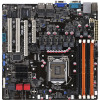
P7F-M WS Motherboard - Asus P7F-M | User Manual - Page 2
Product warranty or service will not be extended if: (1) the product is repaired, modified or altered, unless such repair, modification of alteration is authorized in writing by ASUS; or (2) the serial number of the product is defaced or missing. ASUS PROVIDES THIS MANUAL "AS IS" WITHOUT WARRANTY - Asus P7F-M | User Manual - Page 3
viii About this guide ix Typography x P7F-M WS specifications summary xi Chapter 1: Product introduction 1.1 Welcome 1-3 1.2 Package contents 1-3 1.3 Serial number label 1-4 1.4 Special features 1-4 1.4.1 Product highlights 1-4 1.4.2 Innovative ASUS features 1-6 Chapter 2: Hardware - Asus P7F-M | User Manual - Page 4
the dual function power switch 3-4 Chapter 4: BIOS setup 4.1 Managing and updating your BIOS 4-3 4.1.1 ASUS EZ Flash 2 utility 4-3 4.1.2 BUPDATER utility 4-4 4.1.3 ASUS CrashFree BIOS 3 utility 4-6 4.2 BIOS setup program 4-7 4.2.1 BIOS menu screen 4-8 4.2.2 Menu bar 4-8 4.2.3 Navigation keys - Asus P7F-M | User Manual - Page 5
CPU Configuration 4-16 4.4.2 Chipset 4- ASUS EZ Flash 2 4-36 4.8 Exit menu 4-37 Chapter 5: RAID configuration 5.1 Setting up RAID 5-3 5.1.1 RAID definitions 5-3 5.1.2 Installing hard disk drives 5-4 5.1.3 Setting the RAID item in BIOS 5-4 5.2 Intel® Matrix Storage Manager Option ROM Utility - Asus P7F-M | User Manual - Page 6
LAN driver installation 6-10 6.4 Management applications and utilities installation 6-13 6.4.1 Running the support DVD 6-13 6.4.2 Drivers menu 6-13 6.4.3 Utilities menu 6-14 6.4.4 Make disk menu 6-14 6.4.5 Contact information 6-14 Appendix: Reference information A.1 P7F-M WS block diagram - Asus P7F-M | User Manual - Page 7
energy and, if not installed and used in accordance with manufacturer' s instructions, may cause harmful interference to radio communications. However, there is no guarantee , we published the chemical substances in our products at ASUS REACH website at http://green.asus.com/english/REACH.htm. vii - Asus P7F-M | User Manual - Page 8
qualified service technician or your retailer. Operation safety • Before installing the motherboard and adding devices on it, carefully read all the manuals stable surface. • If you encounter technical problems with the product, contact a qualified service technician or your retailer. This symbol of - Asus P7F-M | User Manual - Page 9
available utilities. • Chapter 6: Driver installation This chapter provides instructions for installing the necessary drivers for different system components. • Appendix: Reference information This appendix includes additional information that you may refer to when configuring the motherboard. Where - Asus P7F-M | User Manual - Page 10
the following symbols used throughout this manual. DANGER/WARNING: Information to prevent injury to yourself when trying to complete a task. CAUTION: Information to prevent damage to the components when trying to complete a task. IMPORTANT: Instructions that you MUST follow to complete - Asus P7F-M | User Manual - Page 11
Model Name P7F-M WS Processor Support / System Bus 1 * Socket LGA1156 Quad Core Intel Xeon 3400 series Server Processor Quad Core Intel Core i7-800 series Desktop Processor Quad Core Intel Core i5-700 series Desktop Processor Dual Core 32nm CPU design Ready Core Logic Intel® 3420 PCH - Asus P7F-M | User Manual - Page 12
P7F-M WS specifications summary Rear I/O Connectors Monitoring Environment External Serial Port External USB Port RJ-45 PS/2 KB/Mouse CPU Temperature FAN RPM 1 2 2 1 V V Operation temperature: 10℃-35℃ Non operation temperature: -40℃-70℃ Non operation humidity: 20%-90% (Non condensing) * - Asus P7F-M | User Manual - Page 13
This chapter describes the motherboard introPdruoc1dtuiocnt features and the new technologies it supports. - Asus P7F-M | User Manual - Page 14
Chapter summary 1 1.1 Welcome 1-3 1.2 Package contents 1-3 1.3 Serial number label 1-4 1.4 Special features 1-4 ASUS P7F-M WS - Asus P7F-M | User Manual - Page 15
the list below. 1.2 Package contents Check your motherboard package for the following items. Standard Gift Box Pack P7F-M WS Cables SATA data cable 6 Accessories IO shield 1 Card ASUS MIO audio card 1 Application CD Support CD 1 Documentation User Guide 1 Packing Qty. 1 pcs per carton - Asus P7F-M | User Manual - Page 16
and satisfying solution to your problems. P7F-M WS xxS1xxxxxxxxx Made in China 合格 1.4 Special features 1.4.1 Product highlights Intel® LGA1156 Xeon 3400 Processor Ready This motherboard supports the latest Intel® Xeon 3400 processors in LGA1156 package, which has memory and PCI Express controller - Asus P7F-M | User Manual - Page 17
voltage and core frequency depending on the CPU loading and system speed or power requirement. Serial ATA II technology The motherboard supports the Serial ATA II 3 Gb/s technology through the Serial ATA interface and Intel 3420 chipset. The Serial ATA II specification provides twice the bandwidth - Asus P7F-M | User Manual - Page 18
and voltage monitoring The CPU temperature is monitored to 100% Japan-made Conductive Polymer Capacitors This motherboard uses all high-quality conductive polymer capacitors (2000hrs capacity. 1.4.2 Innovative ASUS features ASUS MIO Audio card Enjoy high-end sound quality! The ASUS MIO audio card is - Asus P7F-M | User Manual - Page 19
This chapter lists the hardware setup procedures that you have to perform when installing system components. It includes description of the jumpers and connectors on the motherboard. 2 Hardware information - Asus P7F-M | User Manual - Page 20
Chapter summary 2 2.1 Before you proceed 2-3 2.2 Motherboard overview 2-4 2.3 Central Processing Unit (CPU 2-8 2.4 System memory 2-13 2.5 Expansion slots 2-15 2.6 Jumpers 2-19 2.7 Connectors 2-22 2.8 G.P. Diagnosis card installation (optional 2-29 ASUS P7F-M WS - Asus P7F-M | User Manual - Page 21
in soft-off mode. This is a reminder that you should shut down the system and unplug the power cable before removing or plugging in any motherboard component. The illustration below shows the location of the onboard LED ASUS P7F-M WS 2-3 - Asus P7F-M | User Manual - Page 22
study the configuration of your chassis to ensure that the motherboard fits into it. To optimize the motherboard features, we highly recommend that you install it in an ATX 1.1 compliant chassis. Ensure to unplug the chassis power cord before installing or removing the motherboard. Failure to do so - Asus P7F-M | User Manual - Page 23
2.2.3 Motherboard layout ASUS P7F-M WS 2-5 - Asus P7F-M | User Manual - Page 24
Express x8 slot (x4 link) or MIO support 5. PCI slots Jumpers 1. Clear RTC RAM (CLRTC1) 2. CPU Fan and Chassis Fan control setting (3-pin CPUFAN_SEL1, CHAFAN_SEL1) 3. LAN controller setting (3-pin LAN_SW1, LAN_SW2) 4. Force BIOS recovery setting (3-pin RECOVERY1) Rear panel connectors - Asus P7F-M | User Manual - Page 25
Black]) 2. USB connector (10-1 pin USB34, USB56) 3. Thermal sensor cable connectors (3-pin TR1) 4. CPU, front and rear fan connectors (4-pin CPU_FAN1, FRNT_FAN1-3, REAR_FAN1) 5. TPM connector (20-1 pin TPM) (4-pin CD) Page 2-24 2-24 2-25 2-25 2-26 2-26 2-27 2-28 2-28 ASUS P7F-M WS 2-7 - Asus P7F-M | User Manual - Page 26
(CPU) The motherboard comes with a surface mount LGA1156 socket designed for the Intel® Xeon 3400 series Processors. • Upon purchase of the motherboard, the motherboard. ASUS will process Return Merchandise Authorization (RMA) requests only if the motherboard comes with the cap on the LGA1156 socket - Asus P7F-M | User Manual - Page 27
of the socket, and then fit the socket alignment keys into the CPU notches. The CPU fits in only one correct orientation. DO NOT force the CPU into the socket to prevent bending the connectors on the socket and damaging the CPU! Gold triangle mark Alignment keys CPU notches ASUS P7F-M WS 2-9 - Asus P7F-M | User Manual - Page 28
6. Apply some Thermal Interface Material to the exposed area of the CPU that the heatsink will be in contact with, ensuring that it is spread in an even thin layer. Some heatsinks come with preapplied thermal paste. - Asus P7F-M | User Manual - Page 29
match the holes on the motherboard. B 2. Push down two fasteners at a time in a diagonal sequence to secure the heatsink and fan assembly in place. A B A A B 1 B A 1 Orient the heatsink and fan assembly such that the CPU fan cable is closest to the CPU fan connector. ASUS P7F-M WS 2-11 - Asus P7F-M | User Manual - Page 30
errors can occur if you fail to plug this connector. 2.3.3 Uninstalling the CPU heatsink and fan To uninstall the CPU heatsink and fan: 1. Disconnect the CPU fan cable from B the connector on the motherboard. 2. Rotate each fastener counterclockwise. 3. Pull up two fasteners at a time in - Asus P7F-M | User Manual - Page 31
1066 or 1333 MHz DIMM • Always install DIMMs with the same CAS latency. For optimum compatibility, it is recommended that you obtain memory modules from the same vendor. DO NOT combine RDIMM and UDIMM. • The motherboard supports x8 DRAM Only and x4 & x16 DRAM are not supported ASUS P7F-M WS 2-13 - Asus P7F-M | User Manual - Page 32
system components. Failure to do so can cause severe damage to both the motherboard and the components. To install a DIMM: 2 1. Press the retaining into a socket to avoid damaging the DIMM. • The DDR3 DIMM sockets do not support DDR and DDR2 DIMMs. DO NOT install DDR or DDR2 DIMMs to the DDR3 DIMM - Asus P7F-M | User Manual - Page 33
the software drivers for the expansion card. When using PCI cards on shared slots, ensure that the drivers support "Share IRQ" or that the cards do not need IRQ assignments. Otherwise, conflicts will arise between the two PCI groups, making the system unstable and the card inoperable. ASUS P7F-M WS - Asus P7F-M | User Manual - Page 34
2.5.3 Interrupt assignments Standard Interrupt assignments IRQ Priority Standard function 0 1 System Timer 1 2 Keyboard Controller 2 - Programmable Interrupt 3* 11 -- 4* 12 Communications Port (COM1) 5* 13 -- 6 14 -- 7* 15 -- 8 3 System CMOS/Real Time Clock 9* 4 ACPI - Asus P7F-M | User Manual - Page 35
the figure below for the location of the slot. 2.5.6 PCI slots The PCI slot supports cards such as a LAN card, USB card, and other cards that comply with PCI 2.3 specifications. PCI_2 slot PCI_1 slot PCI Express x16 slot (x16 link) PCI Express x8 slot with MIO support (x4 link) ASUS P7F-M WS 2-17 - Asus P7F-M | User Manual - Page 36
sensor cable to the device you would like to monitor temperature. 2.5.8 Installing the audio card 1. Locate the PCI Express x8 slot on the motherboard. 2. Align the card connector with the slot and press firmly until the card sits on the slot completely. 2-18 Chapter 2: Hardware information - Asus P7F-M | User Manual - Page 37
RTC RAM, never remove the cap on CLRTC jumper default position. Removing the cap will cause system boot failure! If the steps above do not help, remove the onboard battery and move the jumper again to clear the CMOS RTC RAM data. After the CMOS clearance, reinstall the battery. ASUS P7F-M WS 2-19 - Asus P7F-M | User Manual - Page 38
CPU Fan and Chassis Fan control setting (3-pin CPUFAN_SEL1, CHAFAN_SEL1) These jumpers allow you to switch for fan pin selection. The CPUFAN_SEL1 jumper is for the CPU jumpers allow you to enable or disable the onboard Intel® Intel 82574LGigabit LAN controllers. Set to pins 1-2 to activate - Asus P7F-M | User Manual - Page 39
it becomes corrupted. To update the BIOS: 1. Set the jumper to pins 2-3. 2. Insert the USB flash that contains the original or latest BIOS and turn on the system to recover or update the BIOS. 3. Shut down the system. 4. Set the jumper back to pins 1-2. 5. Turn on the system. ASUS P7F-M WS 2-21 - Asus P7F-M | User Manual - Page 40
2.7 Connectors 2.7.1 Rear panel connectors 1. PS/2 mouse port (green). This port is for a PS/2 mouse. 2. PS/2 keyboard port (purple). This port is for a PS/2 keyboard. 3. USB 2.0 ports 1 and 2. These two 4-pin Universal Serial Bus (USB) ports are available for connecting USB 2.0 devices. 4. Serial - Asus P7F-M | User Manual - Page 41
audio output device via an optical S/PDIF cable. 14. Coaxial S/PDIF Out port. This port connects an external audio output device via a coaxial S/PDIF cable. ASUS P7F-M WS 2-23 - Asus P7F-M | User Manual - Page 42
(7-pin SATA1-4 [Red], 7-pin SATA5-6 [Black]) Supported by the Intel® 3420 chipset, these connectors are for the Serial ATA signal cables opening at the back of the system chassis. These USB connectors comply with USB 2.0 specification that supports up to 480 Mbps connection speed. 2-24 - Asus P7F-M | User Manual - Page 43
. 4. CPU, front and rear fan connectors (4-pin CPU_FAN1, FRNT_FAN1-3, REAR_FAN1) The fan connectors support cooling fans motherboard components. • These are not jumpers! DO NOT place jumper caps on the fan connectors! • All fans feature the ASUS Fan Speed Control technology. ASUS P7F-M WS - Asus P7F-M | User Manual - Page 44
configuring a system with more power-consuming devices. The system may become unstable or may not boot up if the power is inadequate. • This motherboard supports ATX2.0 PSU or later version. • Ensure that your power supply unit (PSU) can provide at least the minimum power required by your system - Asus P7F-M | User Manual - Page 45
depending on the BIOS settings. Pressing the power switch for more than four seconds while the system is ON turns the system OFF. 6. Reset button (2-pin RESET) This 2-pin connector is for the chassis-mounted reset button for system reboot without turning off the system power. ASUS P7F-M WS 2-27 - Asus P7F-M | User Manual - Page 46
8. Front panel audio connector (10-1 pin AAFP) This connector is for a chassis-mounted front panel audio I/O module that supports either HD Audio or legacy AC`97 audio standard. Connect one end of the front panel audio I/O module cable to this connector. We recommend that - Asus P7F-M | User Manual - Page 47
to avoid electrical shock hazard. 1. Locate the TPM connector (20-1 pin TPM) on the motherboard. 2. With the LEDs of the diagnosis card facing to the PCI slots, align the card connector with the TPM connector and press firmly until the card sits on the connector completely. ASUS P7F-M WS 2-29 - Asus P7F-M | User Manual - Page 48
wake up system 85 Show post error D3 Prepare system for memory detection 87 and sizing A4 Enter BIOS setup BIOS boot menu D4 Memory test AC OS in PIC mode D5 Copy BIOS from ROM to RAM AA OS in APIC mode C0 Early CPU initiation 01 S1 C5 Wake up AP 03 S3 0A Initiate - Asus P7F-M | User Manual - Page 49
This chapter describes the power up Powerin3g up sequence, and ways of shutting down the system. - Asus P7F-M | User Manual - Page 50
Chapter summary 3 3.1 Starting up for the first time 3-3 3.2 Turning off the computer 3-4 ASUS P7F-M WS - Asus P7F-M | User Manual - Page 51
switches are off. 3. Connect the power cord to the power connector at the back of the system chassis. 4. Connect the power cord to a power outlet that is equipped with a surge protector. 5. Turn down the key to enter the BIOS Setup. Follow the instructions in Chapter 4. ASUS P7F-M WS 3-3 - Asus P7F-M | User Manual - Page 52
computer 3.2.1 Using the OS shut down function If you are using Windows® 2003 Server: 1. Click the Start button then click Shut Down. 2. Select Shut Down to sleep mode or to soft-off mode, depending on the BIOS setting. Pressing the power switch for more than four seconds lets the system enter the - Asus P7F-M | User Manual - Page 53
This chapter tells how to change the system settings through the BIOS Setup BIOS se4tup menus. Detailed descriptions of the BIOS parameters are also provided. - Asus P7F-M | User Manual - Page 54
Chapter summary 4 4.1 Managing and updating your BIOS 4-3 4.2 BIOS setup program 4-7 4.3 Main menu 4-10 4.4 Advanced menu 4-16 4.5 Power menu 4-29 4.6 Boot menu 4-32 4.7 Tools menu 4-36 4.8 Exit menu 4-37 ASUS P7F-M WS - Asus P7F-M | User Manual - Page 55
motherboard BIOS using the BUPDATER utility. 4.1.1 ASUS EZ Flash 2 utility The ASUS EZ Flash 2 feature allows you to update the BIOS without having to use a DOS‑based utility. Before you start using this utility, download the latest BIOS from the ASUS website at www.asus.com. To update the BIOS - Asus P7F-M | User Manual - Page 56
BIOS file using the BUPDATER utility: 1. Visit the ASUS website at www.asus.com and download the latest BIOS file for the motherboard. Save the BIOS file to a bootable�U��S��B��fl�a�s�h��d�i�s�k��d�r�iv��e��. 2. Copy the BUPDATER utility (BUPDATER.exe) from the ASUS support website at support.asus - Asus P7F-M | User Manual - Page 57
NOT shut down or reset the system while updating the BIOS to prevent system boot failure! 5. The utility returns to the DOS prompt after the BIOS update process is completed. Reboot the system from the hard disk drive. The BIOS update is finished! Please restart your system. C:\> ASUS P7F-M WS 4-5 - Asus P7F-M | User Manual - Page 58
BIOS recovery finished. DO NOT shut down or reset the system while recovering the BIOS! Doing so would cause system boot failure! The recovered BIOS may not be the latest BIOS version for this motherboard. Visit the ASUS website at www.asus.com to download the latest BIOS file. 4-6 Chapter 4: BIOS - Asus P7F-M | User Manual - Page 59
under the Exit Menu. See section 4.8 Exit Menu. • The BIOS setup screens shown in this section are for reference purposes only, and may not exactly match what you see on your screen. • Visit the ASUS website (www.asus.com) to download the latest BIOS file for this motherboard. ASUS P7F-M WS 4-7 - Asus P7F-M | User Manual - Page 60
menu screen Menu items Menu bar Configuration fields General help Main Advanced Power BIOS SETUP UTILITY Boot Tools Exit System Time [13:44:30] System Date [Wed, 08/05/2009] SATA 1 SATA 2 SATA 3 SATA 4 The navigation keys differ from one screen to another. 4-8 Chapter 4: BIOS setup - Asus P7F-M | User Manual - Page 61
the screen. 4.2.9 General help Pop-up window Scroll bar At the top right corner of the menu screen is a brief description of the selected item. ASUS P7F-M WS 4-9 - Asus P7F-M | User Manual - Page 62
menu screen for information on the menu screen items and how to navigate through them. Main Advanced Power BIOS SETUP UTILITY Boot Tools Exit System Time [13:44:30] System Date [Wed, 08/05/2009] SATA 1 SATA 2 SATA 3 SATA 4 SATA 5 SATA 6 : [ST3160812AS] : [Not Detected] : [Not Detected - Asus P7F-M | User Manual - Page 63
supports multi-sector transfer feature. When set to [Disabled], the data transfer from and to the device occurs one sector at a time. Configuration options: [Disabled] [Auto] PIO Mode [Auto] Allows you to select the data transfer mode. Configuration options: [Auto] [0] [1] [2] [3] [4] ASUS P7F-M WS - Asus P7F-M | User Manual - Page 64
, and Reporting Technology. Configuration options: [Auto] [Disabled] [Enabled] 32Bit Data Transfer [Enabled] Enables or disables 32-bit data transfer. Configuration options: [Disabled] [Enabled] 4-12 Chapter 4: BIOS setup - Asus P7F-M | User Manual - Page 65
ATA connectors supported by the driver LSI MegaRAID utility, or Intel® Matrix BIOS. Configuration option: [Disabled] [Enabled] IDE Detect Time Out (Sec) [35] Selects the time out value for detecting ATA/ATAPI devices. Configuration options: [0] [5] [10] [15] [20] [25] [30] [35] ASUS P7F-M WS - Asus P7F-M | User Manual - Page 66
. It appears only when you set the item Configure SATA as from the sub-menu of SATA Configuration to [AHCI]. Main AHCI Settings BIOS SETUP UTILITY SATA Port1 [Not Detected] SATA Port2 [Not Detected] SATA Port3 [Not Detected] SATA Port4 [Not Detected] SATA Port5 [Not Detected] SATA Port6 [Not - Asus P7F-M | User Manual - Page 67
CPU specification. System Memory Displays the auto-detected system memory. System Memory Information Displays system memory information. Main System Memory Information Speed DDR3 800 BIOS SETUP UTILITY DIMM_A1 DIMM_A2 DIMM_B1 DIMM_B2 512 MB, 1R, 800 N/A 512 MB, 1R, 800 N/A ASUS P7F-M WS - Asus P7F-M | User Manual - Page 68
to malfunction. Main Advanced Power BIOS SETUP UTILITY Boot Tools Exit CPU Configuration Chipset Onboard Device Configuration USB Configuration PCIPnP ACPI Configuration Event Log Configuration Intel VT-d [Disabled] SR-IOV Supported [Disabled] Configure CPU. ←→ Select Screen ↑↓ Select Item - Asus P7F-M | User Manual - Page 69
] Intel(R) Virtualization Tech [Enabled] The Intel® Virtualization Technology allows a hardware platform to run multiple operating systems separately and simultaneously, enabling one system to virtually function as several systems. Configuration options: [Disabled] [Enabled] ASUS P7F-M WS 4-17 - Asus P7F-M | User Manual - Page 70
] Intel(R) HT Technology [Enabled] Allows you to enable or disable the Intel Hyper Enabled] Intel(R) C-STATE Tech [Enabled] The Intel® C-State Technology allows the CPU to Technology-supported CPU. Configuration options: [Disabled] [Enabled] The following items appear only when you set the Intel(R) C- - Asus P7F-M | User Manual - Page 71
that you set this item to [Auto] for BIOS to automatically detect the C-State mode supported by your CPU. Configuration options: [Auto] [C1] [C3] CPU will conditionally demote C6 requests to C3 based on the uncore auto-demote information. Configuration options: [Disabled] [Enabled] ASUS P7F-M WS - Asus P7F-M | User Manual - Page 72
Select an item then press to display the sub-menu. Advanced Advanced Chipset Settings BIOS SETUP UTILITY WARNING: Setting wrong values in below sections may cause system to malfunction. Configure CPU Bridge features. Uncore Configuration ←→ Select Screen ↑↓ Select Item Enter Go to Sub - Asus P7F-M | User Manual - Page 73
] Configuration options: [Enabled] [Disabled] MRC Serial Debug Message Level [Disabled] Configuration options: [Disabled] [Minimum] [Maximum] [Test] Memory ECC Function [Enabled] Allows you to enable or disable Memory ECC fucntion. Configuration options: [Disabled] [Enabled] ASUS P7F-M WS 4-21 - Asus P7F-M | User Manual - Page 74
] [Enabled] Data Scramble [Enabled] Configuration options: [Disabled] [Enabled] Memory Thermal Throttling [Disabled] Setting this item to [CLTT] to Closed Loop values can cause the system to malfunction. Advanced BIOS SETUP UTILITY Onboard Devices Configuration HDA Controller OnBoard LAN1 Boot - Asus P7F-M | User Manual - Page 75
controller legacy mode is enabled. If no USB device is detected, the legacy USB support is disabled. Configuration options: [Disabled] [Enabled] [Auto] BIOS EHCI Hand-Off [Enabled] Enables or disables the BIOS EHCI hand-off support. Configuration options: [Disabled] [Enabled] ASUS P7F-M WS 4-23 - Asus P7F-M | User Manual - Page 76
when changing the settings of the PCI/PnP Configuration menu items. Incorrect field values can cause the system to malfunction. Advanced BIOS SETUP UTILITY Advanced PCI/PnP Settings WARNING: Setting wrong values in below sections may cause system to malfunction. Plug And Play O/S [No] PCI - Asus P7F-M | User Manual - Page 77
Advanced ACPI Settings BIOS SETUP UTILITY General ACPI Configuration Advanced ACPI Configuration Chipset ACPI Configuration Advanced S3 Only] [Auto] Repost Video on S3 Resume [No] Determines whether to invoke VGA BIOS POST on S3/STR resume. Configuration options: [No] [Yes] ASUS P7F-M WS 4-25 - Asus P7F-M | User Manual - Page 78
ACPI Configuration Advanced BIOS SETUP UTILITY Advanced ACPI Configuration ACPI 2.0 Support ACPI APIC support BIOS-->AML ACPI table Headless mode [Enabled] [Enabled] [Enabled] [Disabled] Add additional tables as per ACPI 2.0 specifications. ACPI 2.0 Support [Enabled] Specifies the - Asus P7F-M | User Manual - Page 79
Chipset ACPI Configuration Advanced BIOS SETUP UTILITY South Bridge ACPI Configuration Energy Lake Feature APIC ACPI SCI IRQ High Performance Event Timer HPET Memory ] HPET Memory Address [FED00000h] Configuration options: [FED00000h] [FED01000h] [FED02000h] [FED03000h] ASUS P7F-M WS 4-27 - Asus P7F-M | User Manual - Page 80
Event Log Configuration Main Advanced Event Logging details BIOS SETUP UTILITY View Event Log Mark all event as read all events on the event log. 4.4.8 Intel VT-d Configuration [Disabled] Allows you to enable or disable the Intel Virtualization Technology for Directed I/O. Configuration options: - Asus P7F-M | User Manual - Page 81
, WO_USB, audio and onboard LEDs will be switched off at S5 state. 4.5.2 APM Configuration Power BIOS SETUP UTILITY APM Configuration Restore on AC Power Loss [Last State] Power On By RTC Alarm [Disabled] Power , whatever the system state was before the AC power loss. ASUS P7F-M WS 4-29 - Asus P7F-M | User Manual - Page 82
] Enables the Power On by a PS/2 mouse. This feature requires an ATX power supply that provides at least 1A on the +5VSB lead. 4-30 Chapter 4: BIOS setup - Asus P7F-M | User Manual - Page 83
automatically detects and displays the speed of CPU fans, front fans, and rear fans in rotations per minute (RPM). If the fan is not connected to the motherboard, the field shows [N/A]. Fan Speed Control [Generic Mode] Allows you to configure the ASUS Smart Fan feature that smartly adjusts the - Asus P7F-M | User Manual - Page 84
Sub Screen F1 General Help F10 Save and Exit ESC Exit v02.61 (C)Copyright 1985-2009, American Megatrends, Inc. 4.6.1 Boot Device Priority BIOS SETUP UTILITY Boot Boot Device Priority 1st Boot Device 2nd Boot Device 3rd Boot Device 4th Boot Device 5th Boot Device [Removable Dev.] [ATAPI - Asus P7F-M | User Manual - Page 85
BIOS SETUP UTILITY Boot Boot Settings Configuration Quick Boot Full Screen Logo AddOn ROM Display Mode Bootup Num-Lock Wait For 'F1' If Error Hit 'DEL' Message Display [Enabled] [Enabled] [Force BIOS] [On] [Enabled] [Enabled] Allows BIOS : [Disabled] [Enabled] ASUS P7F-M WS 4-33 - Asus P7F-M | User Manual - Page 86
item then press to display the configuration options. BIOS SETUP UTILITY Boot Security Settings Supervisor Password : Not Installed User Password appears. If you forget your BIOS password, you can clear it by erasing the CMOS Real Time Clock (RTC) RAM. See section 2.6 Jumpers for - Asus P7F-M | User Manual - Page 87
in setting a user password. Password Check [Setup] When set to [Setup], BIOS checks for user password when accessing the Setup utility. When set to [Always], BIOS checks for user password both when accessing Setup and booting the system. Configuration options: [Setup] [Always] ASUS P7F-M WS 4-35 - Asus P7F-M | User Manual - Page 88
. Select an item then press to display the submenu. Main Advanced Power BIOS SETUP UTILITY Boot Tools Exit ASUS EZ Flash 2 Press ENTER to run the utility to select and update BIOS. This uitlity supports 1. FAT 12/16/32 (r/w) 2. NTFS (read only) 3. CD-DISC (read only) ←→ Select Screen - Asus P7F-M | User Manual - Page 89
the optimal or failsafe default values for the BIOS items, and save or discard your changes to the BIOS items. Main Advanced Power BIOS SETUP UTILITY Boot Tools Exit Exit Options Exit & Save Changes or make other changes before saving the values to the non-volatile RAM. ASUS P7F-M WS 4-37 - Asus P7F-M | User Manual - Page 90
4-38 Chapter 4: BIOS setup - Asus P7F-M | User Manual - Page 91
This chapter provides instructions for setting up, creating, and configuring RAID sets using the available utilities. 5RAID configuration - Asus P7F-M | User Manual - Page 92
Chapter summary 5 5.1 Setting up RAID 5-3 5.2 Intel® Matrix Storage Manager Option ROM Utility 5-5 ASUS P7F-M WS - Asus P7F-M | User Manual - Page 93
motherboard comes with the Intel® 3420 chipset that allows you to configure Serial ATA hard disk drives as RAID sets. The motherboard supports the following RAID configurations: RAID 0, RAID 1, RAID 10 and RAID 5. • You must install Windows® XP Service disk drives for this setup. ASUS P7F-M WS 5-3 - Asus P7F-M | User Manual - Page 94
5.1.2 Installing hard disk drives The motherboard supports Serial ATA hard disk drives. For RAID]. 4. Save your changes, and then exit the BIOS Setup. Refer to Chapter 4 for details on entering and navigating through the BIOS Setup. Due to chipset limitation, when set any of SATA ports to RAID mode - Asus P7F-M | User Manual - Page 95
connected to the Serial ATA connectors supported by the Southbridge. To enter the Intel® Matrix Storage Manager option ROM utility: 1. Install all the Serial ATA BIOS setup screens shown in this section are for reference only and may not exactly match the items on your screen. ASUS P7F-M WS 5-5 - Asus P7F-M | User Manual - Page 96
RAID set To create a RAID set 1. From the utility main menu, select 1. Create RAID Volume and press . The following screen appears. Intel(R) Matrix Storage Manager option ROM v8.9.0.1023 PCH-D wRAID5 Copyright(C) 2003-09 Intel Corporation. All Rights Reserved. [ CREATE VOLUME MENU ] Name - Asus P7F-M | User Manual - Page 97
lower stripe size for server systems, and a higher stripe size for multimedia computer systems used mainly for audio and video editing. 7. When 1. From the utility main menu, select 1. Create RAID Volume and press . The following screen appears. Intel(R) Matrix Storage ASUS P7F-M WS 5-7 - Asus P7F-M | User Manual - Page 98
2. Enter a name for the recovery set and press . 3. When the RAID Level item is selected, press the up/down arrow key to select Recovery, and then press . 4. When the Disks item is selected, press to select the hard disk drives you want to include in the recovery set. The - Asus P7F-M | User Manual - Page 99
Enter>. The following screen appears. Intel(R) Matrix Storage Manager option ROM v8.9.0.1023 PCH-D wRAID5 Copyright(C) 2003-09 Intel Corporation. All Rights Reserved. Name delete the RAID set and return to the utility main menu, or press to return to the DELETE VOLUME menu. ASUS P7F-M WS 5-9 - Asus P7F-M | User Manual - Page 100
-RAID. Resetting a RAID volume hard disk drive deletes all internal RAID structure on the drive. To reset a RAID set hard disk drive 1. From the utility main menu, select 3. Reset Disks to Non-RAID and press . The following screen appears. [ RESET RAID DATA ] Resetting RAID disk will remove - Asus P7F-M | User Manual - Page 101
press . The following screen appears. Intel(R) Matrix Storage Manager option ROM v8.9.0.1023 PCH-D wRAID5 Copyright(C) 2003-09 Intel Corporation. All Rights Reserved. [ RECOVERY VOLUME . Press after completing your selection and return to the utility main menu. ASUS P7F-M WS 5-11 - Asus P7F-M | User Manual - Page 102
To rebuild the RAID with other non-RAID disk: 1. At the prompt, press + to enter the Intel Matrix Storage Manager option ROM utility. 2. If there is a non-RAID SATA Hard Disk available, the utility will prompt to rebuild the RAID. Press , and then use up/down arrow keys to select - Asus P7F-M | User Manual - Page 103
5. Select Start > Programs > Intel Matrix Storage > Intel Matrix Storage Console or click the Intel Matrix Storage Manager tray icon to load the Intel Matrix Stroage Manager utility. 6. From the View menu, section Rebuilding the RAID with other non-RAID disk on page 5-12. ASUS P7F-M WS 5-13 - Asus P7F-M | User Manual - Page 104
5.2.8 Setting the Boot array in the BIOS Setup Utility You can set the boot priority sequence in the BIOS for your RAID arrays when creating multi-RAID using the Intel® Matrix Storage Manager. To set the boot array in the BIOS: Set at least one of the arrays bootable to boot from the hard disk. 1. - Asus P7F-M | User Manual - Page 105
This chapter provides instructions for installing the necessary drivers for different system components. 6Driver installation - Asus P7F-M | User Manual - Page 106
Chapter summary 6 6.1 RAID driver installation 6-3 6.2 Intel chipset device installation 6-8 6.3 LAN driver installation 6-10 6.4 Management application and utilities installation 6-13 ASUS P7F-M WS - Asus P7F-M | User Manual - Page 107
Menu PCH INTEL RAID Driver PCH LSI RAID Driver Marvell 88SE6145 SATA RAID Driver Marvell 88SE6145 SATA Non-RAID Driver Write DMI FreeDOS command prompt 5. Use the arrow keys to select the type of RAID driver disk you want to create and press to enter the sub-menu. ASUS P7F-M WS 6-3 - Asus P7F-M | User Manual - Page 108
, high-density floppy disk to the floppy disk drive. 7. Press . 8. Follow screen instructions to create the driver disk. To create a RAID driver disk in Windows® environment 1. Start Windows®. 2. Place the motherboard support DVD into the optical drive. 3. Go to the Make Disk menu, and then - Asus P7F-M | User Manual - Page 109
from a mass storage device manufacturer, press S. * If you do not have any device support disks from a mass storage device manufacturer, or do not want to specify additional mass storage devices for use with Windows, press ENTER. S=Specify Additional Device ENTER=Continue F3=Exit ASUS P7F-M WS 6-5 - Asus P7F-M | User Manual - Page 110
-supplied hardware support disk into Drive A: * Press ENTER when ready. ENTER=Continue ESC=Cancel F3=Exit 5. Select the RAID controller driver you need from screen instructions to continue. To an existing Windows® Server OS To install the RAID controller driver on an existing Windows® Server OS - Asus P7F-M | User Manual - Page 111
appear. The screen differs based on the controller. 4. Right-click the RAID controller driver item, and then select Properties from the menu. 5. Click the Driver tab, and then click the Driver Details button to display the RAID controller drivers. 6. Click OK when finished. ASUS P7F-M WS 6-7 - Asus P7F-M | User Manual - Page 112
for the Intel® chipset on the system. You need to manually install the Intel® chipset software on a Windows Server operating system. To install the Intel® chipset device software: 1. Restart the computer, then log on with Administrator privileges. 2. Insert the motherboard/system support DVD to - Asus P7F-M | User Manual - Page 113
5. Select Yes to accept the terms of the License Agreement and continue the process. 6. Read the Readme File Information and press Next to continue the installation. 7. After completing the installation, click Finish to complete the setup process. ASUS P7F-M WS 6-9 - Asus P7F-M | User Manual - Page 114
LAN driver installation This section provides instructions on how to install the Intel® Gigabit LAN controller drivers on a Windows® Server OS. To install the LAN controller drivers 1. Restart the computer, and then log on with Administrator privileges. 2. Insert the motherboard/system support DVD - Asus P7F-M | User Manual - Page 115
5. Click Next when the Intel(R) Network Connections-InstallShield Wizard window appears. 6. Toggle I accept the terms in the license agreement and click Next to continue. 7. Click the Intel(R) PROSet for Windows Device Manager box, and then click Next to start the installation. ASUS P7F-M WS 6-11 - Asus P7F-M | User Manual - Page 116
8. Follow the screen instructions to complete installation. 9. When finished, press Finish to continue. 6-12 Chapter 6: Driver installation - Asus P7F-M | User Manual - Page 117
package contains the drivers, management applications, and utilities that you can install to avail all motherboard features. The contents of the support DVD are subject to change at any time without notice. Visit the ASUS website (www.asus.com) for updates. 6.4.1 Running the support DVD Place the - Asus P7F-M | User Manual - Page 118
displays the software applications and utilities that the motherboard supports. Click an item to install. 6.4.4 Make disk menu The Make disk menu contains items to create the Intel 3420 driver disks. 6.4.5 Contact information Click the Contact tab to display the ASUS contact information. You can - Asus P7F-M | User Manual - Page 119
This appendix includes additional Reference informaAtion information that you may refer to when configuring the motherboard. - Asus P7F-M | User Manual - Page 120
Appendix summary A A.1 P7F-M WS block diagram A-3 ASUS P7F-M WS - Asus P7F-M | User Manual - Page 121
A.1 P7F-M WS block diagram ASUS P7F-M WS A-3 - Asus P7F-M | User Manual - Page 122
A-4 Appendix A: Reference information
-
 1
1 -
 2
2 -
 3
3 -
 4
4 -
 5
5 -
 6
6 -
 7
7 -
8
-
9
-
10
-
11
-
12
-
13
-
14
-
15
-
16
-
17
-
18
-
19
-
20
-
21
-
22
-
23
-
24
-
25
-
26
-
27
-
28
-
29
-
30
-
31
-
32
-
33
-
34
-
35
-
36
-
37
-
38
-
39
-
40
-
41
-
42
-
43
-
44
-
45
-
46
-
47
-
48
-
49
-
50
-
51
-
52
-
53
-
54
-
55
-
56
-
57
-
58
-
59
-
60
-
61
-
62
-
63
-
64
-
65
-
66
-
67
-
68
-
69
-
70
-
71
-
72
-
73
-
74
-
75
-
76
-
77
-
78
-
79
-
80
-
81
-
82
-
83
-
84
-
85
-
86
-
87
-
88
-
89
-
90
-
91
-
92
-
93
-
94
-
95
-
96
-
97
-
98
-
99
-
100
-
101
-
102
-
103
-
104
-
105
-
106
-
107
-
108
-
109
-
110
-
111
-
112
-
113
-
114
-
115
-
116
-
117
-
118
-
119
-
120
-
121
-
122
 |
 |

Motherboard
P7F-M WS