Asus P8H61-M LE CSM R2.0 P8H61-M LE R2.0 User's Manual
Asus P8H61-M LE CSM R2.0 Manual
 |
View all Asus P8H61-M LE CSM R2.0 manuals
Add to My Manuals
Save this manual to your list of manuals |
Asus P8H61-M LE CSM R2.0 manual content summary:
- Asus P8H61-M LE CSM R2.0 | P8H61-M LE R2.0 User's Manual - Page 1
Motherboard P8H61-M LE R2.0 - Asus P8H61-M LE CSM R2.0 | P8H61-M LE R2.0 User's Manual - Page 2
ASUSTeK COMPUTER INC. ("ASUS"). Product warranty or service will not be extended either (1) for free by downloading it from http://support.asus.com/download or (2) for the cost of reproduction and Software licenses. If however you encounter any problems in obtaining the full corresponding source code - Asus P8H61-M LE CSM R2.0 | P8H61-M LE R2.0 User's Manual - Page 3
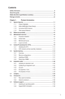
information...vi About this guide...vii P8H61-M LE R2.0 specifications summary ix Package contents...xii Chapter 1: Product introduction 1.1 Special features 1-1 1.1.1 Product highlights 1-1 1.1.2 DIGI+VRM Digital Power Design 1-2 1.1.3 Innovative ASUS features 1-2 1.1.4 Other special - Asus P8H61-M LE CSM R2.0 | P8H61-M LE R2.0 User's Manual - Page 4
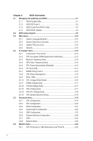
2-3 2.1.4 ASUS BIOS Updater 2-4 2.2 BIOS setup program 2-6 2.3 Main menu 2-10 2.3.1 System Language [English 2-10 2.3.2 System Date [Day xx/xx/xxxx 2-10 2.3.3 System Time [xx:xx:xx 2-10 2.3.4 Security 2-10 2.4 Ai Tweaker menu 2-12 2.4.1 Ai Overclock Tuner [Auto 2-13 2.4.2 CPU bus - Asus P8H61-M LE CSM R2.0 | P8H61-M LE R2.0 User's Manual - Page 5
[Enabled 2-26 2.6.4 CPU Voltage, 3.3V Voltage, 5V Voltage, 12V Voltage 2-27 2.6.5 Anti Surge Support [Enabled 2-27 2.7 Boot menu 2-27 2.7.1 Bootup NumLock State [On 2-27 2.7.2 Full Screen Logo [Enabled 2-27 2.7.3 Wait for 'F1' If Error [Enabled 2-28 2.7.4 Option ROM Messages [Force BIOS 2-28 - Asus P8H61-M LE CSM R2.0 | P8H61-M LE R2.0 User's Manual - Page 6
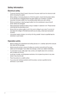
signal cables from the motherboard, ensure that all service technician or your retailer. Operation safety • Before installing the motherboard and adding devices on it, carefully read all the manuals screws, and staples away from connectors, slots, sockets and circuitry. • Avoid dust, humidity, and - Asus P8H61-M LE CSM R2.0 | P8H61-M LE R2.0 User's Manual - Page 7
need when installing and configuring the motherboard. How this guide is organized This guide contains the following parts: • Chapter 1: Product introduction This chapter describes the features of the motherboard and the new technology it supports. • Chapter 2: BIOS information This chapter tells how - Asus P8H61-M LE CSM R2.0 | P8H61-M LE R2.0 User's Manual - Page 8
note of the following symbols used throughout this manual. DANGER/WARNING: Information to prevent injury to yourself when trying to complete a task. CAUTION: Information to prevent damage to the components when trying to complete a task IMPORTANT: Instructions that you MUST follow to complete a task - Asus P8H61-M LE CSM R2.0 | P8H61-M LE R2.0 User's Manual - Page 9
P8H61-M LE R2.0 specifications summary CPU Chipset Memory Graphics Expansion slots Storage LAN Audio USB ASUS unique features LGA1155 socket for Intel® 3rd/2nd Generation Core™ i7 / Core™ i5 / Core™ i3, Pentium®, and Celeron® processors Supports 22/32nm CPU Supports Intel® Turbo Boost technology - Asus P8H61-M LE CSM R2.0 | P8H61-M LE R2.0 User's Manual - Page 10
P8H61-M LE R2.0 specifications summary ASUS unique features ASUS Exclusive overclocking features Back Panel I/O ports Internal I/O connectors ASUS Exclusive Features - ASUS Network iControl* featuring instant network bandwidth domination for top network program in use - ASUS Disk Unlocker - Asus P8H61-M LE CSM R2.0 | P8H61-M LE R2.0 User's Manual - Page 11
P8H61-M LE R2.0 specifications summary Accessories BIOS features Support DVD Form factor 2 x Serial ATA 3.0Gb/s cables 1 x I/O shield 1 x User Manual 1 x Support DVD 64 Mb Flash ROM, UEFI BIOS, PnP, DMI v2.0, WfM 2.0, ACPI v2.0a, Multi-language BIOS, SM BIOS v2.7, F12 Printscreen function, F3 - Asus P8H61-M LE CSM R2.0 | P8H61-M LE R2.0 User's Manual - Page 12
Package contents Check your motherboard package for the following items. P8H61-M LE R2.0 ASUS P8H61-M LE R2.0 motherboard User Manual 2 x Serial ATA 3.0 Gb/s cables 1 x I/O-Shield User Guide Support DVD • If any of the above items is damaged or missing, contact your retailer. • The - Asus P8H61-M LE CSM R2.0 | P8H61-M LE R2.0 User's Manual - Page 13
motherboard supports the H61 Express Chipset Intel® H61 Express Chipset is a single-chipset that supports the 1155 socket Internet applications. * Due to the CPU behavior, DDR3 2133/1866 MHz memory modules run at DDR3 2000/1800 MHz. ** Intel® 3rd generation processors support ASUS P8H61-M LE R2.0 1-1 - Asus P8H61-M LE CSM R2.0 | P8H61-M LE R2.0 User's Manual - Page 14
. 100% All High-quality Conductive Polymer Capacitors This motherboard uses all high-quality conductive polymer capacitors for durability, your network programs. It allows you to automatically connect to a PPPoE network for a more convenient online experience. ASUS UEFI BIOS (EZ Mode) ASUS UEFI BIOS, - Asus P8H61-M LE CSM R2.0 | P8H61-M LE R2.0 User's Manual - Page 15
the CPU default settings when the system hangs due to overclocking failure. C.P.R. eliminates the need to open the system chassis and clear the RTC data. Simply shut down and reboot the system, and the BIOS automatically restores the CPU parameters to their default settings. ASUS P8H61-M LE R2 - Asus P8H61-M LE CSM R2.0 | P8H61-M LE R2.0 User's Manual - Page 16
Sync Video technology, it gaming support the Intel® Quick Sync Video feature. ErP Ready The motherboard is European Union's Energy-related Products (ErP) ready, and ErP requires products to meet certain energy efficiency requirement in regards to energy consumptions. This is in line with ASUS - Asus P8H61-M LE CSM R2.0 | P8H61-M LE R2.0 User's Manual - Page 17
motherboard components or change any motherboard settings. • Unplug the power cord from the wall socket motherboard component. The illustration below shows the location of the onboard LED. SB_PWR P8H61-M LE R2.0 ON OFF Standby Power Powered Off P8H61-M LE R2.0 Onboard LED ASUS P8H61-M LE R2 - Asus P8H61-M LE CSM R2.0 | P8H61-M LE R2.0 User's Manual - Page 18
image below. 1.3.2 Screw holes Place six screws into the holes indicated by circles to secure the motherboard to the chassis. Do not overtighten the screws! Doing so can damage the motherboard. Place this side towards the rear of the chassis P8H61-M LE R2.0 1-6 Chapter 1: Product introduction - Asus P8H61-M LE CSM R2.0 | P8H61-M LE R2.0 User's Manual - Page 19
1.3.3 Motherboard layout 1 23 41 5 19.8cm(7.8in) DVI KB_USB56 DIGI P8H61-M LE R2.0 PCIEX1_1 SATA3G_2 Super Intel® I/O PCIEX1_2 ASM 1085 H61 64Mb BIOS 7 SATA3G_3 ALC887 SPDIF_OUT AAFP LPT PCI1 USB78 USB910 CLRTC SATA3G_4 PANEL SB_PWR 14 13 12 11 10 9 8 ASUS P8H61-M LE R2 - Asus P8H61-M LE CSM R2.0 | P8H61-M LE R2.0 User's Manual - Page 20
connectors (24-pin EATXPWR, 4-pin ATX12V) 3. Serial port connector (10-1 pin COM1) 4. Intel® LGA1155 CPU socket 5. DDR3 DIMM slots 6. TPM connector (20-1 pin TPM) [Optional] 7. Intel® H61 Serial ATA 3.0Gb/s connectors (7-pin SATA3G_1/2/3/4) 8. Standby power LED (SB_PWR) 9. System panel connector (20 - Asus P8H61-M LE CSM R2.0 | P8H61-M LE R2.0 User's Manual - Page 21
Authorization (RMA) requests only if the motherboard comes with the cap on the LGA1155 socket. • The product warranty does not cover damage to the socket contacts resulting from incorrect CPU installation/removal, or misplacement/loss/incorrect removal of the PnP cap. ASUS P8H61-M LE R2.0 1-9 - Asus P8H61-M LE CSM R2.0 | P8H61-M LE R2.0 User's Manual - Page 22
1.4.1 Installing the CPU The LGA1156 CPU is incompatible with the LGA1155 socket. DO NOT install an LGA1156 CPU on the LGA1155 socket. 1 2 A B 3 4 1-10 Chapter 1: Product introduction - Asus P8H61-M LE CSM R2.0 | P8H61-M LE R2.0 User's Manual - Page 23
5 6 B A C 7 ASUS P8H61-M LE R2.0 1-11 - Asus P8H61-M LE CSM R2.0 | P8H61-M LE R2.0 User's Manual - Page 24
1.4.2 CPU heatsink and fan assembly installation Apply the Thermal Interface Material to the CPU heatsink and CPU before you install the heatsink and fan if necessary. To install the CPU heatsink and fan assembly 1 A B 2 B A 3 4 1-12 Chapter 1: Product introduction - Asus P8H61-M LE CSM R2.0 | P8H61-M LE R2.0 User's Manual - Page 25
To uninstall the CPU heatsink and fan assembly 1 2 B A B A ASUS P8H61-M LE R2.0 1-13 - Asus P8H61-M LE CSM R2.0 | P8H61-M LE R2.0 User's Manual - Page 26
installation on a DDR2 DIMM socket. DDR3 modules are developed for better performance with less power consumption. The figure illustrates the location of the DDR3 DIMM sockets: DIMM_A1 DIMM_B1 P8H61-M LE R2.0 Channel Channel A Channel B Sockets DIMM_A1 DIMM_B1 P8H61-M LE R2.0 240-pin DDR3 DIMM - Asus P8H61-M LE CSM R2.0 | P8H61-M LE R2.0 User's Manual - Page 27
. To operate at the vendor-marked or at a higher frequency, refer to section 2.4 Ai Tweaker menu for manual memory frequency adjustment. • For system stability, use a more efficient memory cooling system to support a full memory load (2 DIMMs) or overclocking condition. ASUS P8H61-M LE R2.0 1-15 - Asus P8H61-M LE CSM R2.0 | P8H61-M LE R2.0 User's Manual - Page 28
P8H61-M LE R2.0 Motherboard Qualified Vendors Lists (QVL) DDR3-2400 (O.C.) MHz capability DS - Chip NO. Timing - 9-10-9-28 - 9-11-9-28 - - Voltage 1.65V 1.65V 1.5V-1.7V DIMM socket support (Optional) 1 DIMM 2 DIMMs • • • • • • DDR3-2133 (O.C.) MHz capability Vendors Part No. Size - Asus P8H61-M LE CSM R2.0 | P8H61-M LE R2.0 User's Manual - Page 29
Voltage 1.65V 1.65V 1.50V 1.5V 1.5V 1.5V 1.6V 1.65V 1.65V 1.65V DIMM socket support (Optional) 1 DIMM 2 DIMMs • • • • • • • • • • • -GJ1D Asint 302G08-GG1C - 9 9-9-9-24 - 1.65V 1.5V 1.6V - • • • • • • • • • • • • (continued on the next page) ASUS P8H61-M LE R2.0 1-17 - Asus P8H61-M LE CSM R2.0 | P8H61-M LE R2.0 User's Manual - Page 30
Kingston Kingston Micron Micron Micron Micron Part No. Size SS/ Chip DS Brand Chip NO. Timing Voltage DIMM socket support (Optional) 1 DIMM 2 DIMMs AD31333001GOU 1GB SS A-Data AD30908C8D-151C E0906 - - • • AD31333G001GOU 3GB(3 x 1GB) SS - - 8-8-8-24 1.65-1.85V • • AD31333002GOU - Asus P8H61-M LE CSM R2.0 | P8H61-M LE R2.0 User's Manual - Page 31
9 7-7-7-20 8-8-8-24 7-7-7-20 8-8-8-24 8-8-8-24 - DIMM socket support Voltage (Optional) 1 DIMM 2 DIMMs 1.65V • • • - • • - • • - • • - • • - • • - • • - • • - • • 1.5V • • 1.5V • • 1.5V • • 1.5V • • 1.5V • • - • • - • • ASUS P8H61-M LE R2.0 1-19 - Asus P8H61-M LE CSM R2.0 | P8H61-M LE R2.0 User's Manual - Page 32
Timing Voltage DIMM socket support (Optional) 1 memory configuration. • DDR3 1600 MHz and higher memory frequency is supported by Intel® 3rd generation processors. • Due to the CPU behavior, DDR3 2133/1866 memory module will run at DDR3 2000/1800 MHz frequency. • Visit the ASUS website at www.asus - Asus P8H61-M LE CSM R2.0 | P8H61-M LE R2.0 User's Manual - Page 33
Simultaneously press the retaining clips outward to unlock the DIMM. 2 1 Support the DIMM lightly with your fingers when pressing the retaining clips. The DIMM might get damaged when it flips out 1 with extra force. DIMM notch 2. Remove the DIMM from the socket. ASUS P8H61-M LE R2.0 1-21 - Asus P8H61-M LE CSM R2.0 | P8H61-M LE R2.0 User's Manual - Page 34
the system unit cover (if your motherboard is already installed in a chassis BIOS settings, if any. See Chapter 2 for information on BIOS setup. 2. Assign an IRQ to the card. 3. Install the software drivers for the expansion card. When using PCI cards on shared slots, ensure that the drivers support - Asus P8H61-M LE CSM R2.0 | P8H61-M LE R2.0 User's Manual - Page 35
slot This motherboard supports PCI Express 2.0 x1 network cards, motherboard has a PCI Express 3.0/2.0 x16 slot (at 16x mode) that supports PCI Express 2.0 x16 graphic cards complying with the PCI Express specifications. Intel® 3rd generation Core™ processors support PCIe 3.0. ASUS P8H61-M LE R2 - Asus P8H61-M LE CSM R2.0 | P8H61-M LE R2.0 User's Manual - Page 36
CMOS memory of date, time, and system setup parameters by erasing the CMOS RTC RAM data. The onboard button cell battery powers the RAM data in CMOS, which include system setup information such as system passwords. P8H61-M LE R2.0 CLRTC 12 23 Normal (Default) Clear RTC P8H61-M LE R2.0 Clear - Asus P8H61-M LE CSM R2.0 | P8H61-M LE R2.0 User's Manual - Page 37
mouse. 2. LAN (RJ-45) port. This port allows Gigabit connection to a Local Area Network (LAN) through a network hub. Refer to the table below for the LAN port LED indications. LAN port LED indications audio module in the front panel to support an 8-channel audio output. ASUS P8H61-M LE R2.0 1-25 - Asus P8H61-M LE CSM R2.0 | P8H61-M LE R2.0 User's Manual - Page 38
HD-audio-compliant Legacy AC'97 pin definition compliant definition P8H61-M LE R2.0 Front panel audio connector • We recommend that you connect a high-definition front panel audio module to this connector to avail of the motherboard's high-definition audio capability. • If you want to connect - Asus P8H61-M LE CSM R2.0 | P8H61-M LE R2.0 User's Manual - Page 39
. Find the proper orientation and push down firmly until the connectors completely fit. P8H61-M LE R2.0 ATX12V EATXPWR +12V DC +12V DC +3 Volts +12 Volts +12 Volts at http://support.asus. com/PowerSupplyCalculator/PSCalculator.aspx?SLanguage=en-us for details. ASUS P8H61-M LE R2.0 1-27 - Asus P8H61-M LE CSM R2.0 | P8H61-M LE R2.0 User's Manual - Page 40
+12V GND P8H61-M LE R2.0 Fan connectors Do not forget to connect the fan cables to the fan connectors. Insufficient air flow inside the system may damage the motherboard components. These are not jumpers! Do not place jumper caps on the fan connectors! • The CPU_FAN connector supports a CPU fan of - Asus P8H61-M LE CSM R2.0 | P8H61-M LE R2.0 User's Manual - Page 41
connector (26-1 pin LPT) The LPT (Line Printing Terminal) connector supports devices such as a printer. LPT is standardized as IEEE 1284, which is the parallel port interface on IBM PC-compatible computers. LPT P8H61-M LE R2.0 P8H61-M LE R2.0 Parallel Port Connector AFD ERR# INIT# SLIN# GND GND GND - Asus P8H61-M LE CSM R2.0 | P8H61-M LE R2.0 User's Manual - Page 42
SATA3G_1 SATA3G_2 SATA3G_3 P8H61-M LE R2.0 SATA3G_4 P8H61-M LE R2.0 SATA 3.0Gb/s connectors • You must install Windows® XP Service Pack 3 or BIOS, click Advanced Mode > Advanced tab > SATA Configuration > SATA Mode Selection. • When using hot-plug and NCQ, set the SATA Mode Selection item in the BIOS - Asus P8H61-M LE CSM R2.0 | P8H61-M LE R2.0 User's Manual - Page 43
5V USB_P7USB_P7+ GND P8H61-M LE R2.0 PIN 1 PIN 1 P8H61-M LE R2.0 USB2.0 connectors Never connect a 1394 cable to the USB connectors. Doing so will damage the motherboard! The USB module cable is purchased separately. 9. TPM connector (20-1 pin TPM) [Optional] This connector supports a Trusted - Asus P8H61-M LE CSM R2.0 | P8H61-M LE R2.0 User's Manual - Page 44
-8 pin PANEL) This connector supports several chassis-mounted functions. PLED SPEAKER PLED+ PLED+5V Ground Ground Speaker PANEL PIN 1 IDE_LED+ IDE_LED- PWR Ground Reset Ground P8H61-M LE R2.0 IDE_LED PWRSW RESET * Requires an ATX power supply P8H61-M LE R2.0 System panel connector • System - Asus P8H61-M LE CSM R2.0 | P8H61-M LE R2.0 User's Manual - Page 45
only. Click an icon to display Support DVD/motherboard information Click an item to install If Autorun is NOT enabled in your computer, browse the contents of the Support DVD to locate the file ASSETUP.EXE from the BIN folder. Double-click the ASSETUP.EXE to run the DVD. ASUS P8H61-M LE R2.0 1-33 - Asus P8H61-M LE CSM R2.0 | P8H61-M LE R2.0 User's Manual - Page 46
1-34 Chapter 1: Product introduction - Asus P8H61-M LE CSM R2.0 | P8H61-M LE R2.0 User's Manual - Page 47
update the motherboard BIOS in Windows® environment. • ASUS Update requires an Internet connection either through a network or an Internet Service Provider (ISP). • This utility is available in the support DVD that comes with the motherboard package. Installing ASUS Update To install ASUS Update - Asus P8H61-M LE CSM R2.0 | P8H61-M LE R2.0 User's Manual - Page 48
ASUS Update utility is capable of updating itself through the Internet. Always update the utility to avail all its features. Updating from a BIOS file a. Select Update BIOS from file, then click Next. b. Locate the BIOS file from the Open window, then click Open. 3. Follow the onscreen instructions - Asus P8H61-M LE CSM R2.0 | P8H61-M LE R2.0 User's Manual - Page 49
requires you to enter BIOS Setup to recover BIOS setting. To ensure system compatibility and stability, we recommend that you press to load default BIOS values. DO NOT shut down or reset the system while updating the BIOS! Doing so can cause system boot failure! ASUS P8H61-M LE R2.0 2-3 - Asus P8H61-M LE CSM R2.0 | P8H61-M LE R2.0 User's Manual - Page 50
screen displays may not be same as shown. Before updating BIOS 1. Prepare the motherboard support DVD and a USB flash drive in FAT32/16 format and single partition. 2. Download the latest BIOS file and BIOS Updater from the ASUS website at http://support.asus.com and save them on the USB flash drive - Asus P8H61-M LE CSM R2.0 | P8H61-M LE R2.0 User's Manual - Page 51
BIOS default settings to ensure system compatibility and stability. Select the Load Optimized Defaults item under the Exit menu. Refer to section 2.9 Exit menu for details. • Ensure to connect all SATA hard disk drives after updating the BIOS file if you have disconnected them. ASUS P8H61-M LE R2 - Asus P8H61-M LE CSM R2.0 | P8H61-M LE R2.0 User's Manual - Page 52
what you see on your screen. • Visit the ASUS website at www.asus.com to download the latest BIOS file for this motherboard. • Ensure that a USB mouse is connected to your motherboard if you want to use the mouse to control the BIOS setup program. • If the system becomes unstable after changing - Asus P8H61-M LE CSM R2.0 | P8H61-M LE R2.0 User's Manual - Page 53
to display all fan speeds if available Displays the CPU/motherboard temperature, CPU/5V/3.3V/12V voltage output, CPU/chassis fan speed Exits the BIOS setup program without saving the changes, saves the is available only when the boot device is installed to the system. ASUS P8H61-M LE R2.0 2-7 - Asus P8H61-M LE CSM R2.0 | P8H61-M LE R2.0 User's Manual - Page 54
provides advanced options for experienced end-users to configure the BIOS settings. The figure below shows an example of the Advanced Mode. Refer to the following sections for the detailed configurations. To access the EZ Mode, click Exit, then select ASUS EZ Mode. Back button Menu items Menu bar - Asus P8H61-M LE CSM R2.0 | P8H61-M LE R2.0 User's Manual - Page 55
. Navigation keys At the bottom right corner of the menu screen are the navigation keys for the BIOS setup program. Use the navigation keys to select items in the menu and change the settings. General of a field, select it and press to display a list of options. ASUS P8H61-M LE R2.0 2-9 - Asus P8H61-M LE CSM R2.0 | P8H61-M LE R2.0 User's Manual - Page 56
information, and allows you to set the system date, time, language, and security settings. 2.3.1 System Language [English] Allows you to choose the BIOS language version from the options. Configuration options: [English] [Español 2.3.2 System Date [Day xx/xx/xxxx] Allows you to set the system - Asus P8H61-M LE CSM R2.0 | P8H61-M LE R2.0 User's Manual - Page 57
accessing the system. Otherwise, you might be able to see or change only selected fields in the BIOS setup program. To set an administrator password: 1. Select the Administrator Password item and press . User Password item on top of the screen shows Not Installed. ASUS P8H61-M LE R2.0 2-11 - Asus P8H61-M LE CSM R2.0 | P8H61-M LE R2.0 User's Manual - Page 58
of the Ai Tweaker menu items. Incorrect field values can cause the system to malfunction. The configuration options for this section vary depending on the CPU and DIMM model you installed on the motherboard. Scroll down to display the following items: 2-12 Chapter 2: Getting started - Asus P8H61-M LE CSM R2.0 | P8H61-M LE R2.0 User's Manual - Page 59
you to set the CPU bus speed to DRAM speed ratio mode. Configuration options: [Auto] [100:100] [100:133] 2.4.3 Memory Frequency [Auto] Allows you to set the memory operating frequency. Configuration Power Saving Mode] [Medium Power Saving Mode] [Max Power Saving Mode] ASUS P8H61-M LE R2.0 2-13 - Asus P8H61-M LE CSM R2.0 | P8H61-M LE R2.0 User's Manual - Page 60
you to set the CPU ratio and features. CPU Ratio [Auto] Allows you to manually adjust the maximum non-turbo CPU ratio. Use and keys or the numeric keypad to adjust the value. The valid value ranges vary according to your CPU model. Enhanced Intel SpeedStep Technology [Enabled] Allows you - Asus P8H61-M LE CSM R2.0 | P8H61-M LE R2.0 User's Manual - Page 61
. CPU Current Capability [100%] Allows you to configure the total power range, and extends the overclocking frequency range simultaneously. Configuration options: [100%] [110%] [120%] Choose a higher value when overclocking, or under a high CPU loading for extra power support. ASUS P8H61-M LE R2 - Asus P8H61-M LE CSM R2.0 | P8H61-M LE R2.0 User's Manual - Page 62
the Offset voltage. The values range from 0.005V to 0.635V with a 0.005V interval. CPU Manual Voltage [Auto] This item appears only when you set the CPU Voltage item to [Manual Mode] and allows you to set a fixed CPU voltage. The values range from 0.800V to 1.990V with a 0.005V interval. Refer to - Asus P8H61-M LE CSM R2.0 | P8H61-M LE R2.0 User's Manual - Page 63
Manual Voltage, iGPU Offset Voltage, iGPU Manual Voltage, DRAM Voltage, VCCSA Voltage and PCH Voltage items are labeled in different color, indicating the risk levels of high voltage settings. • The system may need better cooling system to work stably under high voltage settings. ASUS P8H61-M LE R2 - Asus P8H61-M LE CSM R2.0 | P8H61-M LE R2.0 User's Manual - Page 64
[Auto] [+0.10V] 2.4.15 [Auto] [Disabled] [Enabled] CPU Spread Spectrum [Auto] Automatic configuration. Enhances the BCLK overclocking ability. menu The Advanced menu items allow you to change the settings for the CPU and other system devices. Be cautious when changing the settings of the Advanced - Asus P8H61-M LE CSM R2.0 | P8H61-M LE R2.0 User's Manual - Page 65
perform adjacent cache line prefetching. CPU Power Management Configuration CPU Ratio [Auto] Allows you to set the ratio between the CPU Core Clock and the BCLK Frequency. Use and keys to adjust the ratio. The valid value ranges vary according to your CPU model. ASUS P8H61-M LE R2.0 2-19 - Asus P8H61-M LE CSM R2.0 | P8H61-M LE R2.0 User's Manual - Page 66
controls the CPU speed. Turbo Mode [Enabled] Allows you to enable or disable the Intel® Turbo Mode Technology. [Disabled] CPU C1E [Auto] Allows you to enable or disable the CPU C1E. [Auto] Set this item automatically. [Disabled] Disables this function. [Enabled] Enables the C1E support - Asus P8H61-M LE CSM R2.0 | P8H61-M LE R2.0 User's Manual - Page 67
BIOS AHCI allows the onboard storage driver to enable advanced Serial ATA the order of commands. • Due to H61 Chipset limitation, AHCI Mode only works on (Self-Monitoring, Analysis and Reporting Technology) is a monitor system. When read support more than four SATA devices. ASUS P8H61-M LE R2.0 2-21 - Asus P8H61-M LE CSM R2.0 | P8H61-M LE R2.0 User's Manual - Page 68
MVP function support, set this item to [Enabled] to empower both the integrated and discrete graphic cards. The iGPU shared memory size will Support [Enabled] [Enabled] Enables the support for USB devices on legacy operating systems (OS). [Disabled] The USB devices can be used only for the BIOS - Asus P8H61-M LE CSM R2.0 | P8H61-M LE R2.0 User's Manual - Page 69
to legacy AC'97 or highdefinition audio depending on the audio standard that the front panel audio module supports. [HD] Sets the front panel audio connector (AAFP) mode to high definition audio. [AC97] items appear only when you set the Parallel Port item to [Enabled]. ASUS P8H61-M LE R2.0 2-23 - Asus P8H61-M LE CSM R2.0 | P8H61-M LE R2.0 User's Manual - Page 70
Change Settings [Auto] Allows you to select an optimal setting for Super I/O devices. Configuration options: [IO=378h; IRQ=5] [IO=378h; IRQ=5,6,7,9,10,11,12] [IO=278h; IRQ=5,6,7,9,10,11,12] [IO=3BCh; IRQ=5,6,7,9,10,11,12] Device Mode [STD Printer Mode] Allows you to select the Printer Port Mode. - Asus P8H61-M LE CSM R2.0 | P8H61-M LE R2.0 User's Manual - Page 71
you to change the fan settings. 2.6.1 CPU Temperature / MB Temperature �[x�x�x��º�C�/x�x�x��º�F�] The onboard hardware monitor automatically detects and displays the CPU and motherboard temperatures. Select Ignore if you do not wish to display the detected temperatures. ASUS P8H61-M LE R2.0 2-25 - Asus P8H61-M LE CSM R2.0 | P8H61-M LE R2.0 User's Manual - Page 72
displays the CPU and chassis fan speeds in rotations per minute (RPM). If the fan is not connected to the motherboard, the CPU fan speed. [Manual] Sets to [Manual] to assign detailed fan speed control parameters. The following four items appear only when you set CPU Fan Profile to [Manual]. CPU - Asus P8H61-M LE CSM R2.0 | P8H61-M LE R2.0 User's Manual - Page 73
CPU Voltage, 3.3V Voltage, 5V Voltage, 12V Voltage The onboard hardware monitor automatically detects the voltage output through the onboard voltage regulators. Select Ignore if you do not want to detect this item. 2.6.5 Anti Surge Support use the ASUS MyLogo 2™ feature. ASUS P8H61-M LE R2.0 2-27 - Asus P8H61-M LE CSM R2.0 | P8H61-M LE R2.0 User's Manual - Page 74
. Configuration options: [Disabled] [Enabled] 2.7.4 Option ROM Messages [Force BIOS] [Force BIOS] The third-party ROM messages will be forced to display during the boot Safe Mode, do any of the following: • Press when ASUS Logo appears. • Press after POST. 2.7.9 Boot Override These - Asus P8H61-M LE CSM R2.0 | P8H61-M LE R2.0 User's Manual - Page 75
your CMOS settings, press , and then select Yes. • DO NOT shut down or reset the system while updating the BIOS to prevent the system boot failure! • We recommend that you update the BIOS file only coming from the same memory/ CPU configuration and BIOS version. ASUS P8H61-M LE R2.0 2-29 - Asus P8H61-M LE CSM R2.0 | P8H61-M LE R2.0 User's Manual - Page 76
you to load the optimal default values for the BIOS items, and save or discard your changes to the BIOS items. You can access the EZ Mode from the , a confirmation window appears. Select Yes to discard changes and exit. ASUS EZ Mode This option allows you to enter the EZ Mode screen. Launch EFI - Asus P8H61-M LE CSM R2.0 | P8H61-M LE R2.0 User's Manual - Page 77
radiate radio frequency energy and, if not installed and used in accordance with manufacturer's instructions, may cause harmful interference to radio communications. However, there is no guarantee that for compliance could void the user's authority to operate this equipment. P8H61-M LE R2.0 A-1 - Asus P8H61-M LE CSM R2.0 | P8H61-M LE R2.0 User's Manual - Page 78
appareil numérique de la Classe B respecte toutes les exigences du Règlement sur le matériel brouilleur du Canada. Cet appareil est conforme aux normes CNR exemptes de licence d'Industrie Canada. Le fonctionnement est soumis aux deux conditions suivantes : (1) cet appareil - Asus P8H61-M LE CSM R2.0 | P8H61-M LE R2.0 User's Manual - Page 79
ASUS REACH website at http://csr.asus.com/english/REACH.htm. DO NOT throw the motherboard placed in municipal waste. ASUS Recycling/Takeback Services ASUS recycling and takeback programs come asus.com/english/Takeback.htm for detailed recycling information in different regions. P8H61-M LE R2.0 A-3 - Asus P8H61-M LE CSM R2.0 | P8H61-M LE R2.0 User's Manual - Page 80
CA 94539, USA Telephone +1-812-282-3777 Fax +1-510-608-4555 Web site usa.asus.com Technical Support Telephone Support fax Online support +1-812-282-2787 +1-812-284-0883 support.asus.com ASUS COMPUTER GmbH (Germany and Austria) Address Harkort Str. 21-23, D-40880 Ratingen, Germany - Asus P8H61-M LE CSM R2.0 | P8H61-M LE R2.0 User's Manual - Page 81
TAIWAN Authorized representative in Europe: ASUS COMPUTER GmbH Address, City: HARKORT STR. 21-23, 40880 RATINGEN Country: GERMANY declare the following apparatus: Product name : Motherboard Model name : P8H61-M LE R2.0, P8H61-M LE USB3 R2.0, P8H61-M LE CSM R2.0 conform with the essential
-
 1
1 -
 2
2 -
 3
3 -
 4
4 -
 5
5 -
 6
6 -
 7
7 -
8
-
9
-
10
-
11
-
12
-
13
-
14
-
15
-
16
-
17
-
18
-
19
-
20
-
21
-
22
-
23
-
24
-
25
-
26
-
27
-
28
-
29
-
30
-
31
-
32
-
33
-
34
-
35
-
36
-
37
-
38
-
39
-
40
-
41
-
42
-
43
-
44
-
45
-
46
-
47
-
48
-
49
-
50
-
51
-
52
-
53
-
54
-
55
-
56
-
57
-
58
-
59
-
60
-
61
-
62
-
63
-
64
-
65
-
66
-
67
-
68
-
69
-
70
-
71
-
72
-
73
-
74
-
75
-
76
-
77
-
78
-
79
-
80
-
81
 |
 |

Motherboard
P8H61-M LE R2.0