Asus PCH-DL User Manual
Asus PCH-DL Manual
 |
View all Asus PCH-DL manuals
Add to My Manuals
Save this manual to your list of manuals |
Asus PCH-DL manual content summary:
- Asus PCH-DL | User Manual - Page 1
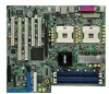
Motherboard PCH-DL User Guide - Asus PCH-DL | User Manual - Page 2
any means, except documentation kept by the purchaser for backup purposes, without the express written permission of ASUSTeK COMPUTER INC. ("ASUS"). Product warranty or service will not be extended if: (1) the product is repaired, modified or altered, unless such repair, modification of alteration - Asus PCH-DL | User Manual - Page 3
guide vii PCH-DL specifications summary ix Chapter 1: Product introduction 1.1 Welcome 1-1 1.2 Package contents 1-1 1.3 Special features 1-2 Chapter 2: Hardware information 2.1 Before you proceed 2-1 2.2 Motherboard Messages 3-2 3.3 Powering off the computer 3-4 3.3.1 Using the OS shut down - Asus PCH-DL | User Manual - Page 4
4.4 Advanced menu 4-12 4.4.1 Advanced BIOS Features 4-12 4.4.2 CPU Configuration 4-13 4.4.3 Memory Configuration 4-14 4.4.4 Chipset 4-15 4.4.5 Onboard Device 4-18 4.4.6 Configuration 4-34 4.6.5 Security 4-35 4.7 Exit menu 4-37 Appendix: Reference information A.1 PCH-DL block diagram A-1 iv - Asus PCH-DL | User Manual - Page 5
. This equipment generates, uses and can radiate radio frequency energy and, if not installed and used in accordance with manufacturer's instructions, may cause harmful interference to radio communications. However, there is no guarantee that interference will not occur in a particular installation - Asus PCH-DL | User Manual - Page 6
signal cables from the motherboard, ensure that all service technician or your retailer. Operation safety • Before installing the motherboard and adding devices on it, carefully read all the manuals screws, and staples away from connectors, slots, sockets and circuitry. • Avoid dust, humidity, and - Asus PCH-DL | User Manual - Page 7
the motherboard. How this guide is organized This manual contains the following parts: • Chapter 1: Product introduction This chapter describes the features of the PCH-DL motherboard. It includes brief descriptions of the special attributes of the motherboard and the new technology it supports - Asus PCH-DL | User Manual - Page 8
used in this guide To make sure that you perform certain tasks properly, take note of the following symbols used throughout this manual. WARNING: Information to 1. ASUS Websites The ASUS websites worldwide provide updated information on ASUS hardware and software products. Refer to the ASUS contact - Asus PCH-DL | User Manual - Page 9
PCH-DL specifications summary CPU Chipset Front Side Bus (FSB) Memory Expansion slots Storage LAN IEEE 1394 Audio Special features Rear panel I/O Dual 604-pin sockets for Intel® Xeon™ Processors 3.2GHz with Hyper-Threding Technology On-die 1MB/512KB L2 cache North bridge: Intel® 82875P Memory - Asus PCH-DL | User Manual - Page 10
PCH-DL specifications summary Internal I/O BIOS features Industry standard Manageability Power requirement Form Factor Support CD contents CPU/SYSTEM/CHASSIS fan connectors 24-pin/8-pin SSI-type 12V power connectors 20-pin front panel connectors Chassis intrusion connector 1 x IEEE 1394 - Asus PCH-DL | User Manual - Page 11
Chapter 1 This chapter describes the features of the motherboard. It includes brief explanations of the special attributes of the motherboard and the new technology it supports. Product introduction - Asus PCH-DL | User Manual - Page 12
Chapter summary 1.1 Welcome 1-1 1.2 Package contents 1-1 1.3 Special features 1-2 ASUS PCH-DL motherboard - Asus PCH-DL | User Manual - Page 13
of power computing! Before you start installing the motherboard, and hardware devices on it, check the items in your package with the list below. 1.2 Package contents Check your PCH-DL package for the following items. ASUS PCH-DL motherboard ASUS support CD 4 x SATA cables 2 x SATA power cables - Asus PCH-DL | User Manual - Page 14
The motherboard supports dual Intel® Xeon™ Processors via 604-pin surface mount ZIF sockets. The processor has 1MB/512KB L2 cache, includes a 533/400MHz system bus, and features the Intel Hyper-Threading Technology that allows up to 3.2GHz core frequencies. Dual-channel DDR333 memory support - Asus PCH-DL | User Manual - Page 15
computers, peripherals, and consumer electronic devices such as camcorders, VCRs, printers,TVs, and digital cameras. 6-channel audio feature The SoundMAX-class ADI AD1980 AC '97 audio CODEC supports 6-channel 5.1 surround sound the voice messages in different languages. ASUS PCH-DL motherboard 1-3 - Asus PCH-DL | User Manual - Page 16
ASUS EZ Flash BIOS With the ASUS EZ Flash, you can easily update the system BIOS even before loading the operating system. No need to use a DOS-based utility or boot from a floppy disk. C.P.R. (CPU Parameter Recall) The C.P.R. feature of the motherboard BIOS allows automatic re-setting to the BIOS - Asus PCH-DL | User Manual - Page 17
Chapter 2 This chapter describes the hardware setup procedures that you have to perform when installing system components. It includes details on the switches, jumpers, and connectors on the motherboard. Hardware information - Asus PCH-DL | User Manual - Page 18
Chapter summary 2.1 Before you proceed 2-1 2.2 Motherboard installation 2-2 2.3 Central Processing Unit (CPU 2-5 2.4 System memory 2-12 2.5 Expansion slots 2-15 2.6 Jumpers 2-18 2.7 Connectors 2-21 ASUS PCH-DL motherboard - Asus PCH-DL | User Manual - Page 19
install motherboard components or change any motherboard settings. 1. Unplug the power cord from the wall socket before touching PCH-DL PCH-DL Onboard LED ON OFF CPU Type/Voltage CPU Type/Voltage not identical identical SB_PWR1 ON Standby Power OFF Powered Off ASUS PCH-DL Deluxe motherboard - Asus PCH-DL | User Manual - Page 20
it. Make sure to unplug the power cord before installing or removing the motherboard. Failure to do so may cause you physical injury and damage motherboard components. 2.2.1 Placement direction When installing the motherboard, make sure that you place it into the chassis in the correct orientation - Asus PCH-DL | User Manual - Page 21
PRI_IDE1 PROMISE PDC20378 RAID Controller PRI_RAID1 Super I/O GAME1 PCIX2 (64-bit, 66MHz 3V) PCI3 (32-bit, 33MHz 5V) TI TSB43AB22A SYS_FAN1 PCH-DL IEEE1394_1 J3 SB_PWR1 SATA_RAID1 SATA_RAID2 CLRTC1 CHASSIS1 IDE_LED1 SMB1 PANEL1 FLOPPY1 30.5cm (12in) ASUS PCH-DL Deluxe motherboard 2-3 - Asus PCH-DL | User Manual - Page 22
2.2.4 Layout Contents Sockets/Slots 1. CPU sockets 2. DDR DIMM sockets 3. PCI-X/PCI slots 4. AGP Pro slot Page 2-5 2- 2-20 4. USB device wake-up (3-pin USBPW1, USBPW2) 2-20 5. RAID enable (3-pin J2) 2-21 6. Clear RTC RAM (3-pin CLRTC1) 2-21 Rear panel connectors 1. PS/2 mouse port 2-22 - Asus PCH-DL | User Manual - Page 23
GAME/MIDI connector (16-1 pin GAME1) 2-30 13. Internal audio connectors (4-pin CD1, AUX1, MODEM1) 2-30 14. Front panel audio connector (10-1 pin FP_AUDIO1) 2-31 15. Hard disk activity Soft-off switch (2-pin PWR_SW) 2-32 - Reset switch (2-pin RESET) 2-32 ASUS PCH-DL Deluxe motherboard 2-5 - Asus PCH-DL | User Manual - Page 24
Unit (CPU) 2.3.1 Overview The motherboard comes with dual surface mount 604-pin Zero Insertion Force (ZIF) sockets. The sockets are designed for the Intel® Xeon™ Processor in the 604-pin package with 1MB/512KB L2 cache. Prestonia PCH-DL PCH-DL Socket 604 Gold Arrow 2.3.2 Installing the CPU - Asus PCH-DL | User Manual - Page 25
4. Carefully push down the socket lever to secure the CPU. The lever clicks on the side tab to indicate that it is locked. 5. Apply the thermal interface material (thermal grease) to the top of the CPU. This thermal grease should come with the CPU package. ASUS PCH-DL Deluxe motherboard 2-7 - Asus PCH-DL | User Manual - Page 26
Refer to the installation manual that came with the CPU package for details on heatsink/fan assembly and installation. To install the CPU heatsink and fan: 1. With the motherboard on a flat stable surface (such as a table), place the thermal plate underneath a CPU socket, matching the standoffs on - Asus PCH-DL | User Manual - Page 27
mechanism with the thermal plate using four screws. 4. Position the heatsink on top of the CPU, having its angled side (with cut corners) facing the memory sockets. Make sure that the heatsink base fits completely on the retention mechanism. Heatsink angled side ASUS PCH-DL Deluxe motherboard 2-9 - Asus PCH-DL | User Manual - Page 28
5. Secure the heatsink with the retention clips. Retention clip a. Insert the center hole of a retention clip into the center tab on the retention mechanism. b. Slightly move the clip to the right so that the center tab is 5a positioned on the narrow side of the hole. This ensures that the 5c - Asus PCH-DL | User Manual - Page 29
. NOTE You may need to slightly press out the side of the retention mechanism to properly insert the Side rail air tunnel. Groove (inner side) ASUS PCH-DL motherboard 2-11 - Asus PCH-DL | User Manual - Page 30
should snap over the dents on the retention mechanism. Rail stopper Side rail 12. Connect the fan cable to the connector CPU_FAN1 on the motherboard. Make sure to connect to the correct fan connector. Otherwise, you will get a warning message during POST. Protruding tabs Fan connector Fan cable - Asus PCH-DL | User Manual - Page 31
memory 2.4.1 Overview The motherboard comes with four Double Data Rate (DDR) Dual Inline Memory Module (DIMM) sockets. The following figure illustrates the location of the DDR DIMM sockets. DIMM_B2 DIMM_A2 DIMM_B1 80 Pins DIMM_A1 104 Pins PCH-DL PCH-DL 184-Pin DDR DIMM Sockets 2.4.2 Memory - Asus PCH-DL | User Manual - Page 32
) and identical DIMM pair in DDR2 and DDR4 (black sockets) Table 2 Memory frequency/CPU FSB synchronization CPU FSB 533 MHz 400 MHz DDR DIMM Type PC2700/PC2100 PC2100 Memory Frequency 333/266 MHz 266 MHz Obtain DDR DIMMs only from ASUS qualified vendors for better system performance. Visit the - Asus PCH-DL | User Manual - Page 33
to remove a DIMM. 1. Simultaneously press the retaining clips outward to unlock the DIMM. Support the DIMM lightly with your fingers when pressing the retaining clips. The DIMM might get damaged when it flips out with extra force. 2. Remove the DIMM from the socket. ASUS PCH-DL motherboard 2-15 - Asus PCH-DL | User Manual - Page 34
motherboard has two 64-bit PCI-X slots and three 32-bit PCI slots. The following subsections describe the slots and the expansion cards that they support system unit cover (if your motherboard is already installed in a chassis BIOS settings, if any. See Chapter 4 for information on BIOS setup - Asus PCH-DL | User Manual - Page 35
- - - - - - - - - When using PCI cards on shared slots, ensure that the drivers support "Share IRQ" or that the cards do not need IRQ assignments. Otherwise, conflicts will arise between the two PCI groups, making the system unstable and the card inoperable. ASUS PCH-DL motherboard 2-17 - Asus PCH-DL | User Manual - Page 36
. Note the notches on the card golden fingers to ensure that they fit the AGP slot on your motherboard. Install only +0.8V or +1.5V AGP cards. This motherboard does not support 3.3V AGP cards. 2-18 Keyed for 1.5V PCH-DL PCH-DL Accelerated Graphics Port (AGP) Chapter 2: Hardware information - Asus PCH-DL | User Manual - Page 37
-DL Keyboard Power Setting 2. CPU external frequency selection (3-pin J1) This jumper allows you to select your desired CPU external frequency (or bus clock). J1 1 2 3 4 CPU select frequency (Default) 3 4 5 6 100MHz PCH-DL PCH-DL CPU External Frequency Selection ASUS PCH-DL motherboard - Asus PCH-DL | User Manual - Page 38
1394 controller. Set to pins 1-2 to activate the 1394 feature. PCH-DL PCH-DL 1394 Function Setting J3 12 23 Enable (Default) Disable 4. USB device wake-up (3-pin USBPW1, USBPW2) Set these jumpers to +5V to wake up the computer from S1 sleep mode (CPU stopped, DRAM refreshed, system running - Asus PCH-DL | User Manual - Page 39
the boot process and enter BIOS setup to re-enter data. PCH-DL PCH-DL Clear RTC RAM CLRTC1 12 23 Normal (Default) Clear CMOS Except when clearing the RTC RAM, never remove the cap on CLRTC jumper default position. Removing the cap will cause system boot failure! ASUS PCH-DL motherboard 2-21 - Asus PCH-DL | User Manual - Page 40
, printers, or digital cameras. 4. RJ-45 port. This port allows connection to a Local Area Network (LAN) through a network hub. 5. Line In port. This Line In (light blue) port connects a tape player or other audio sources. In 6-channel mode, the function of this port becomes Bass/Center. 6. Line Out - Asus PCH-DL | User Manual - Page 41
the Intel® 6300ESB ICH. SATA1 GND RSATA_TXP1 RSATA_TXN1 GND RSATA_RXN1 RSATA_RXP1 GND PCH-DL PCH-DL SATA Connectors GND RSATA_TXP2 RSATA_TXN2 GND RSATA_RXN2 RSATA_RXP2 GND SATA2 The Serial ATA RAID feature (RAID 0/1) is available only if you are using Windows XP. ASUS PCH-DL motherboard 2-23 - Asus PCH-DL | User Manual - Page 42
-1 pin PRI_IDE[blue], SEC_IDE [black) This connector supports the provided UltraDMA/100/66 IDE hard disk ribbon the UltraDMA cable connector. This prevents incorrect orientation when you connect the cables. PCH-DL PCH-DL IDE Connectors SEC_IDE1 PIN 1 PRI_IDE1 PIN 1 NOTE: Orient the red markings - Asus PCH-DL | User Manual - Page 43
UltraATA cable and installed UltraATA 133 hard disks. 2. The Promise® PDC20378 RAID controller does not support ATAPI devices such as CD-ROMs, DVD-ROMs, etc. 3. For RAID 0 and RAID 1 configurations, use both Parallel ATA and Serial ATA devices for better performance. ASUS PCH-DL motherboard 2-25 - Asus PCH-DL | User Manual - Page 44
SATA_RAID2) These Serial ATA connectors support SATA hard disks that you may configure as a RAID set. Through the onboard Promise® PDC20378 RAID controller, you may create a RAID0, RAID1, RAID0+1, or multiRAID configuration. SATA_RAID1 SATA_RAID2 PCH-DL PCH-DL SATA RAID Connectors 1. If you wish to - Asus PCH-DL | User Manual - Page 45
not boot up if the power is inadequate. 24-pin Power Connector 8-pin 12V 12V 12V 12V PCH-DL PCH-DL ATX Power Connectors +3 Volts -12 Volts Ground PSON# Ground Ground Ground -5 Volts +5 Volts +5 GND GND For Power Supply with 20-pin Power Connector GND GND ASUS PCH-DL motherboard 2-27 - Asus PCH-DL | User Manual - Page 46
with a jumper cap. If you wish to use the chassis intrusion detection feature, remove the jumper cap from the pins. CHASSIS1 (Default) PCH-DL PCH-DL Chassis Intrusion Connector 9. IEEE 1394 connector (10-1 pin IEEE1394_1) This connector is for a 1394 module. Attach the 10-1 pin 1394 cable plug - Asus PCH-DL | User Manual - Page 47
Digital audio connector (4-1 pin SPDIF_O1) This S/PDIF Out connector is available for an S/PDIF audio module. Connect one end of the S/PDIF audio cable to this connector and the other end to the S/PDIF module. +5V SPDIFOUT GND SPDIF_01 PCH-DL PCH-DL Digital Audio Connector ASUS PCH-DL motherboard - Asus PCH-DL | User Manual - Page 48
files. +5V J1B2 J1CY GND GND J1CX J1B1 +5V PCH-DL PCH-DL Game Connector GAME1 MIDI_IN J2B2 J2CY MIDI_OUT J2CX J2B1 +5V 13. Internal audio connectors (4-pin CD1, AUX1, MODEM1) These connectors allow you to receive stereo audio input from sound sources such as a CD-ROM, TV tuner, or MPEG card - Asus PCH-DL | User Manual - Page 49
the front panel audio cable. FP_AUDIO1 MIC2 MICPWR Line out_R NC Line out_L AGND +5VA BLINE_OUT_R BLINE_OUT_L PCH-DL PCH-DL Intel Panel PCH-DL PCH-DL IDE Activity LED IDE_LED1 -+ TIP: If the case-mounted LED does not light up, try reversing the 2-pin plug. ASUS PCH-DL motherboard 2- - Asus PCH-DL | User Manual - Page 50
5V HD_LED+ HD_LEDSpeaker LAN_ACT +5VSB MLED PWR Ground Reset Ground PCH-DL PCH-DL System Panel Connector Message LED Reset SW ATX Power Switch* the system between ON and SLEEP, or ON and SOFT OFF, depending on the BIOS or OS settings. Pressing the power switch while in the ON mode for more than - Asus PCH-DL | User Manual - Page 51
Chapter 3 This chapter describes the power up sequence and gives information on the BIOS beep codes. Powering up - Asus PCH-DL | User Manual - Page 52
Chapter summary 3.1 Starting up for the first time 3-1 3.2 Powering off the computer 3-2 ASUS PCH-DL motherboard - Asus PCH-DL | User Manual - Page 53
read/write test error Motherboard timer not operational Keyboard controller BAT test error General exception error Display memory error CMOS shutdown register read/write error 7. At power on, hold down to enter BIOS Setup. Follow the instructions in Chapter 4. ASUS PCH-DL motherboard 3-1 - Asus PCH-DL | User Manual - Page 54
CPU test System failed memory test System failed VGA test System failed due to CPU over-clocking Action • Install an Intel® Xeon™ Processor into the CPU socket. • Check the CPU if properly installed. • Call ASUS technical support for assistance. See the "ASUS contact information." • Install 184 - Asus PCH-DL | User Manual - Page 55
• Check your power supply and make sure it is not defective. • Call ASUS technical support for assistance. See the "ASUS contact information." System completed Power-On Self Test • No action required Computer now booting to operating system • No action required ASUS PCH-DL motherboard 3-3 - Asus PCH-DL | User Manual - Page 56
option button is selected, then click the OK button to shut down the computer. 3. The power supply should turn off after Windows® shuts down. If you are using Windows® XP or Windows® Server 2003: 1. Click the Start button then select Turn Off Computer. 2. Click the Turn Off button to shut down the - Asus PCH-DL | User Manual - Page 57
Chapter 4 This chapter tells how to change system settings through the BIOS Setup menus. Detailed descriptions of the BIOS parameters are also provided. BIOS setup - Asus PCH-DL | User Manual - Page 58
Chapter summary 4.1 Managing and updating your BIOS 4-1 4.2 BIOS Setup program 4-3 4.3 Main menu 4-6 4.4 Advanced menu 4-12 4.5 Power menu 4-26 4.6 Boot menu 4-32 4.7 Exit menu 4-37 ASUS PCH-DL motherboard - Asus PCH-DL | User Manual - Page 59
My Computer. c. In the My Computer window, click the 3 1/2 Floppy icon. d. From the Menu bar, click File > Format. e. Select "Create an MS-DOS Startup Disk" in the Format Options field, then click Start. 2. Copy the original (or the latest) motherboard BIOS to the bootable floppy disk. ASUS PCH-DL - Asus PCH-DL | User Manual - Page 60
AwardBIOS Flash Utility (AWDFLASH.EXE). Follow these instructions to update the BIOS using this utility. 1. Download the latest BIOS file from the ASUS web site. Rename the file to *.BIN and save it to a floppy disk. 2. Insert the disk that contains the new BIOS file into the floppy drive. Save only - Asus PCH-DL | User Manual - Page 61
various sub-menus and make your selections among the predetermined choices. Because the BIOS software is constantly being updated, the following BIOS setup screens and descriptions are for reference purposes only, and may not exactly match what you see on your screen. ASUS PCH-DL motherboard 4-3 - Asus PCH-DL | User Manual - Page 62
4.2.1 BIOS menu screen Menu bar Menu items General help Time (hh:mm:ss) Date (mm:dd:yy) Legacy Diskette A Floppy 3 Mode Support Primary IDE Master Primary IDE Slave Secondary IDE Master Secondary IDE Slave Third IDE Master Fourth IDE Master Base Memory Extended Memory Total Memory 11: 10 : 30 Wed - Asus PCH-DL | User Manual - Page 63
do not fit on the screen. Press Up/Down arrow keys or PageUp/PageDown keys to display the other items on the screen. 4.2.7 Pop-up window Select an item in the menu, then press Enter to display a pop-up window with the configuration options for that item. ASUS PCH-DL motherboard 4-5 - Asus PCH-DL | User Manual - Page 64
. Time (hh:mm:ss) Date (mm:dd:yy) Legacy Diskette A Floppy 3 Mode Support Primary IDE Master Primary IDE Slave Secondary IDE Master Secondary IDE Slave Third IDE Master Fourth IDE Master Base Memory Extended Memory Total Memory 11: 10 : 30 Wed, Mar 24 2004 [1.44M, 3.5 in.] [Disabled] [None] [None - Asus PCH-DL | User Manual - Page 65
as the BIOS attempts to Manually detecting an IDE drive." If no drive is installed or if you are removing a drive and not replacing it, select [None]. Configuration options: [None] [Auto] [Manual] The IDE drive information items are grayed out when this item is set to [Auto]. ASUS PCH-DL motherboard - Asus PCH-DL | User Manual - Page 66
Set this item to [CHS] if the Primary IDE Master item is set to [Manual] so you can manually enter the drive values. Configuration options: [CHS] [LBA] [Large] [Auto] allows improved transfer speeds and data integrity for supported IDE drives. Configuration options: [Disabled] [Auto] 4-8 Chapter - Asus PCH-DL | User Manual - Page 67
drive manufacturer. Incorrect settings may cause the system to fail to recognize the installed IDE drive! To manually enter the number of cylinder, head, precomp, landing zone, and sector per track for the . Head Shows the number of the hard disk read/write heads. ASUS PCH-DL motherboard 4-9 - Asus PCH-DL | User Manual - Page 68
, if any, on the motherboard. Landing Zone Displays the drive's maximum usable capacity as calculated by the BIOS based on the drive information Analysis, and Reporting Technology (S.M.A.R.T.) status if the IDE hard disk drive supports the feature. Otherwise, this item is grayed out and shows the - Asus PCH-DL | User Manual - Page 69
IDE Master When configuring a drive as Fourth IDE Master, refer to section "4.3.1 Primary IDE Master" and section "4.3.5 Third IDE Master" for the menu item descriptions. ASUS PCH-DL motherboard 4-11 - Asus PCH-DL | User Manual - Page 70
the settings of the Advanced menu items. Incorrect field values may cause the system to malfunction! Advanced BIOS Features CPU Configuration Memory Configuration Chipset Onboard Device Speech Configuration PCIPnP USB Configuration Select Menu Item Specific Help Virus Protection, Boot Sequence - Asus PCH-DL | User Manual - Page 71
may cause the system to become unstable! Chipset Vcore Voltage [+1.6V] Allows adjustment of the chipset Vcore voltage. Configuration options: [+1.5V] , such as Windows XP or Linux 2.4. Otherwise, set this item to [Disabled]. Configuration options: [Disabled] [Enabled] ASUS PCH-DL motherboard 4-13 - Asus PCH-DL | User Manual - Page 72
to CAS# Delay, and DRAM RAS# Precharge are configurable only when the Memory Timing Selectable item is set to [Manual]. CAS Latency Time [2.5] This item sets the latency (in clocks) between DRAM clocks used for DRAM parameters. Configuration options: [8] [7] [6] [5] 4-14 Chapter 4: BIOS Setup - Asus PCH-DL | User Manual - Page 73
BIOS. Configuration options: [Disabled] [Enabled] Video BIOS Cacheable [Disabled] Allows you to enable or disable the cache function of the video BIOS. Setting to [Enabled] improves the display speed by caching the display data. Configuration options: [Disabled] [Enabled] ASUS PCH-DL motherboard - Asus PCH-DL | User Manual - Page 74
) [128] Select Menu Item Specific Help Size of the AGP Aperture. AGP Aperture Size [128] This feature allows you to select the size of mapped memory for AGP graphic data. Configuration options: [4] [8] [16] [32] [64] [128] [256] 4-16 Chapter - Asus PCH-DL | User Manual - Page 75
a value within the specified range, then press Enter. Configuration options: [Min=12] [Max=23] The minimum and maximum configuration values depend on the installed CPU. ASUS PCH-DL motherboard 4-17 - Asus PCH-DL | User Manual - Page 76
the configuration options. Onboard Device Onboard AC97 Audio CSA LAN (Giga-LAN) Onboard LAN Boot ROM Onboard 1394 Chip Onboard Promise Controller Operating Mode SuperIO Device SATA Configuration [Auto] [Enabled] [Disabled] [Disabled] [Enabled] [RAID] Select Menu Item Specific Help Enable/Disable - Asus PCH-DL | User Manual - Page 77
the Onboard Promise Controller item is set to [Enabled]. Configuration options: [IDE] [RAID] SuperIO Device SuperIO Device Serial Port1 Address Serial Port2 Address Onboard Parallel Port Parallel Port to [EPP] or [ECP+EPP]. Configuration options: [EPP 1.7] [EPP 1.9] ASUS PCH-DL motherboard 4-19 - Asus PCH-DL | User Manual - Page 78
Menu Item Specific Help [Disabled]: Disable SATA Controller. [Auto]: Auto-arrange the BIOS. [Combined Mode]: PATA and SATA are combined. Max. of 2 IDE drives on each channel. [Enhanced Mode]: Enable both SATA and PATA. Max. of 6 IDE drives are supported. [SATA Only]: SATA is opeating in legacy mode - Asus PCH-DL | User Manual - Page 79
you to set the SATA Port0 and Serial ATA Port1 modes. The options for these items vary depending on the setting of the On-Chip Serial ATA item. Configuration options: [Primary Master] [Primary Slave] [Secondary Master] [Secondary Slave] [STA0 Master] [SATA1 Master] ASUS PCH-DL motherboard 4-21 - Asus PCH-DL | User Manual - Page 80
4.4.6 Speech Configuration This menu shows the ASUS POST Reporter™ configuration settings. Select an item then press Enter to display a pop-up menu Disabled] Allows you enable or disable the system boot error reporting function. Configuration options: [Disabled] [Enabled] 4-22 Chapter 4: BIOS Setup - Asus PCH-DL | User Manual - Page 81
[Auto(ESCD)], allows BIOS to automatically configure of all boot and Plug and Play devices. When set to [Manual], you can assign the problem. If you are using a standard VGA card, leave this field to the default setting [Disabled]. Configuration options: [Disabled] [Enabled] ASUS PCH-DL motherboard - Asus PCH-DL | User Manual - Page 82
item Resources Controlled By to [Manual] to enable the item IRQ Pin 4 Assignment [Disabled] [Manual] [Disabled] [Auto] [Auto Help When resources are controlled manually, assign each system interrupt with the original PC AT bus specification, parameter is set to [Manual]. Select [PCI Device] to - Asus PCH-DL | User Manual - Page 83
support in the BIOS to turn on automatically when you install high speed USB devices. Configuration options: [Disabled] [Enabled] USB Legacy Mode Support [Enabled] Allows you enable or disable support for the legacy USB devices. Configuration options: [Disabled] [Enabled] ASUS PCH-DL motherboard - Asus PCH-DL | User Manual - Page 84
then press Enter to display the configuration options. ACPI APIC Support ACPI Suspend Type APM Configuration Hardware Configuration [Enabled] [S1&S3] Select Menu Item Specific Help Enable/Disable ACPI support for Operating System. ACPI APIC Support [Enabled] Allows you to enable or disable the - Asus PCH-DL | User Manual - Page 85
Min] [20 Min] [30 Min] [40 Min] [1 Hr] Suspend Type [Stop Grant] Allows you to select the suspend type. Configuration options: [Stop Grant] [PwrOn Suspend] ASUS PCH-DL motherboard 4-27 - Asus PCH-DL | User Manual - Page 86
Method [DPMS] This item determines the video off features. The Display Power Management System (DPMS) feature allows the BIOS to control the video display card if it supports the DPMS feature. [Blank Screen] only blanks the screen. Use this for monitors without power management or "green" features - Asus PCH-DL | User Manual - Page 87
=0, Max=59), then press Enter. 5. Press tab to move to the seconds field, then press Enter. 6. Key-in a value (Min=0, Max=59), then press Enter. ASUS PCH-DL motherboard 4-29 - Asus PCH-DL | User Manual - Page 88
Specific Help CPU VCORE Voltage, +12V Voltage, +3.3V Voltage, +5VCC Voltage, VBAT Voltage, +5VSB Voltage Auto-detected voltages through the onboard voltage regulators. 4-30 Chapter 4: BIOS Setup - Asus PCH-DL | User Manual - Page 89
] [55oC/131oF] [60oC/140oF] [65oC/149oF] CPU Q-Fan Tolerance Value [ 5] Allows you to set the smart CPU fan speed detection range. Configuration options: [Min = 1] [Max = 5] ASUS PCH-DL motherboard 4-31 - Asus PCH-DL | User Manual - Page 90
Boot Device [CDROM] 3rd Boot Device [Hard Disk] These items allow you to select your boot device priority. Configuration options: [Removable] [Hard Disk] [CDROM] [Legacy LAN] [Disabled] 4-32 Chapter 4: BIOS Setup - Asus PCH-DL | User Manual - Page 91
> or arrow to select a device, then press to move it up, or to move it down the list. Press to exit this menu. ASUS PCH-DL motherboard 4-33 - Asus PCH-DL | User Manual - Page 92
feature. Setting to [Enabled] clear the case open status. Configuration options: [Disabled] [Enabled] Boot Up Floppy Seek [Enabled] When enabled, the BIOS will seek the floppy disk drive to determine whether the drive has 40 or 80 tracks. Configuration options: [Disabled] [Enabled] 4-34 Chapter - Asus PCH-DL | User Manual - Page 93
: [250] [500] [750] [1000] 4.6.5 Security Security Supervisor Password User Password Password Check Clear Clear [Setup] Select Menu Item Specific Help Supervisor password control full access. ASUS PCH-DL motherboard 4-35 - Asus PCH-DL | User Manual - Page 94
by the onboard button cell battery. If you need to erase the CMOS RAM, refer to section "2.6 Jumpers" for instructions. Password Check [Setup] This field requires you to enter the password before entering the BIOS setup or the system. Select [Setup] to require the password before entering the - Asus PCH-DL | User Manual - Page 95
Exit menu items allow you to load the BIOS setup default settings, save or discard any >, to save your changes to CMOS before exiting the Setup utility. When a confirmation window appears, type [Y] to save and exit, or [N] to cancel and return to and return to the menu. ASUS PCH-DL motherboard 4-37 - Asus PCH-DL | User Manual - Page 96
4-38 Chapter 4: BIOS Setup - Asus PCH-DL | User Manual - Page 97
Appendix This appendix includes additional information that you may refer to when confiiguring the motherboard. Reference information - Asus PCH-DL | User Manual - Page 98
Appnedix summary A-1 Block diagram A-1 ASUS PCH-DL motherboard - Asus PCH-DL | User Manual - Page 99
1394) Audio Codec ADI AD1980 AC97 1 IDE Port (Ultra ATA 66/100) IDE Promise PDC20378 SATA SATA Supports 2 Serial ATA Ports RAID0/RAID1 Winbond 83627THF Super I/O 1xParallel,Floppy 2xSerial, KB,MS,Game Port, HW monitor USB USB USB USB 4 USB1.1/2.0 Ports 4Mb BIOS (FWH) ASUS PCH-DL motherboard - Asus PCH-DL | User Manual - Page 100
A-2 Appendix: Reference information
-
 1
1 -
 2
2 -
 3
3 -
 4
4 -
 5
5 -
 6
6 -
 7
7 -
8
-
9
-
10
-
11
-
12
-
13
-
14
-
15
-
16
-
17
-
18
-
19
-
20
-
21
-
22
-
23
-
24
-
25
-
26
-
27
-
28
-
29
-
30
-
31
-
32
-
33
-
34
-
35
-
36
-
37
-
38
-
39
-
40
-
41
-
42
-
43
-
44
-
45
-
46
-
47
-
48
-
49
-
50
-
51
-
52
-
53
-
54
-
55
-
56
-
57
-
58
-
59
-
60
-
61
-
62
-
63
-
64
-
65
-
66
-
67
-
68
-
69
-
70
-
71
-
72
-
73
-
74
-
75
-
76
-
77
-
78
-
79
-
80
-
81
-
82
-
83
-
84
-
85
-
86
-
87
-
88
-
89
-
90
-
91
-
92
-
93
-
94
-
95
-
96
-
97
-
98
-
99
-
100
 |
 |

Motherboard
PCH-DL
User Guide