Asus PR-DL Manual PDF file for PR-DLS533
Asus PR-DL Manual
 |
View all Asus PR-DL manuals
Add to My Manuals
Save this manual to your list of manuals |
Asus PR-DL manual content summary:
- Asus PR-DL | Manual PDF file for PR-DLS533 - Page 1
Motherboard PR-DLS533 User Guide - Asus PR-DL | Manual PDF file for PR-DLS533 - Page 2
Product warranty or service will not be extended if: (1) the product is repaired, modified or altered, unless such repair, modification of alteration is authorized in writing by ASUS; or (2) the serial number of the product is defaced or missing. ASUS PROVIDES THIS MANUAL "AS IS" WITHOUT WARRANTY - Asus PR-DL | Manual PDF file for PR-DLS533 - Page 3
guide ix Where to find more information ix ASUS contact information x PR-DLS533 specifications summary xi Chapter 1: Product introduction 1.1 Welcome 1-1 1.2 Package contents 1-1 1.3 Special features 1-2 1.3.1 Product highlights 1-2 1.3.2 Value-added solutions 1-4 1.4 Motherboard overview - Asus PR-DL | Manual PDF file for PR-DLS533 - Page 4
2-11 2.6.1 Installing an expansion card 2-11 2.6.2 Configuring an expansion card 2-11 2.6.3 PCI slots 2-13 2.7 Switches and jumpers 2-14 2.7.1 Switches 2-14 2.7.2 Jumpers 2-15 2.8 Connectors 2-18 Chapter 3: Powering up 3.1 Starting up for the first time 3-1 3.2 Powering off the computer - Asus PR-DL | Manual PDF file for PR-DLS533 - Page 5
in Windows® 2000 ..... 5-24 5.4 Microsoft® Windows® XP Professional 5-25 5.4.1 LSI® SCSI Driver Installation 5-25 5.4.2 Intel® LAN Driver Installation 5-29 5.5 Novell® NetWare® Server 5-31 5.5.1 LSI® SCSI Driver Installation 5-31 5.5.2 Intel® LAN Driver Installation 5-33 5.5.3 ATI® Rage XL - Asus PR-DL | Manual PDF file for PR-DLS533 - Page 6
used in accordance with manufacturer's instructions, may cause harmful interference to radio by turning the equipment off and on, the user is encouraged to try to correct the interference by the dealer or an experienced radio/TV technician for help. The use of shielded cables for connection of the - Asus PR-DL | Manual PDF file for PR-DLS533 - Page 7
from the motherboard, ensure that slots, sockets and circuitry. • Avoid dust, humidity, and temperature extremes. Do not place the product in any area where it may become wet. • Place the product on a stable surface. • If you encounter technical problems with the product, contact a qualified service - Asus PR-DL | Manual PDF file for PR-DLS533 - Page 8
About this guide This user guide contains the information you need when installing the ASUS PR-DLS533 motherboard. How this guide is organized This manual contains the following parts: • Chapter 1: Product introduction This chapter describes the features of the PR-DLS533 motherboard. It includes - Asus PR-DL | Manual PDF file for PR-DLS533 - Page 9
in this guide To make sure that you perform certain tasks properly, take note of the following symbols used throughout this manual. WARNING: ASUS Websites The ASUS websites worldwide provide updated information on ASUS hardware and software products. The ASUS websites are listed in the ASUS - Asus PR-DL | Manual PDF file for PR-DLS533 - Page 10
CA 94538, USA General Fax: +1-510-608-4555 General Email: [email protected] Technical Support Support Fax: +1-510-608-4555 General Support: +1-502-933-8713 Web Site: www.asus.com Support Email: [email protected] ASUS COMPUTER GmbH (Germany and Austria) Address: Harkortstr. 25, 40880 Ratingen - Asus PR-DL | Manual PDF file for PR-DLS533 - Page 11
PR-DLS533 specifications summary CPU Chipsets Front Side Bus (FSB) Memory Onboard LAN Onboard SCSI Onboard VGA Expansion slots Rear panel I/O Internal connectors BIOS features Support for Intel® Xeon™ processor On-die 512KB L2 cache RCC Grand Champion LE Server (GCLE) RCC Champion South Bridge 5.0 - Asus PR-DL | Manual PDF file for PR-DLS533 - Page 12
PR-DLS533 specifications summary Form Factor Support CD contents Extended ATX form factor: 12 in x 13 in (30.5 cm x 33 cm) Device drivers Management software Utilities Contact information * Specifications are subject to change without notice. xii - Asus PR-DL | Manual PDF file for PR-DLS533 - Page 13
Chapter 1 This chapter describes the features of the PR-DLS533 motherboard. It includes brief explanations of the special attributes of the motherboard and the new technology it supports. Product introduction - Asus PR-DL | Manual PDF file for PR-DLS533 - Page 14
Chapter summary 1.1 Welcome 1-1 1.2 Package contents 1-1 1.3 Special features 1-2 1.4 Motherboard overview 1-6 ASUS PR-DLS533 motherboard - Asus PR-DL | Manual PDF file for PR-DLS533 - Page 15
//33 IDE drives 68-pin LVD SCSI cable for Ultra320 SCSI devices Ribbon cable for a 3.5-inch floppy drive Bag of extra jumper caps PR-DLS533 User Guide LSI SCSI Controller User's Manual If any of the above items is damaged or missing, contact your retailer. ASUS PR-DLS533 motherboard user guide 1-1 - Asus PR-DL | Manual PDF file for PR-DLS533 - Page 16
1.3 Special features 1.3.1 Product highlights Latest processor technology The PR-DLS533 motherboard supports the Intel® Xeon processor via dual 603/604-pin surface mount ZIF sockets. The processor features the Intel® NetBurst™ micro-architecture that includes hyper-pipelined technology, a rapid - Asus PR-DL | Manual PDF file for PR-DLS533 - Page 17
-bit PCI-X Gigabit Ethernet controller to support the latest LAN technologies. The Intel® 82551QM Fast Ethernet controller is an option. Onboard VGA The ATI Rage-XL PCI-based VGA controller integrates an 8MB display SDRAM to provide onboard video solution. ASUS PR-DLS533 motherboard user guide 1-3 - Asus PR-DL | Manual PDF file for PR-DLS533 - Page 18
-Up features. Server management The motherboard comes with an ASMC connector that supports the optional ASMC-HE/ME/LE card to comply with server reliability, availability, and serviceability requirements. Remote management response via remote diagnostics and troubleshooting still works even when the - Asus PR-DL | Manual PDF file for PR-DLS533 - Page 19
power management for configuring and managing all system components, 32-bit device drivers, and installation procedures for Windows NT/2000/XP. Color-coded connectors and descriptive icons make identification easy as required by the PC '99 specification. ASUS PR-DLS533 motherboard user guide 1-5 - Asus PR-DL | Manual PDF file for PR-DLS533 - Page 20
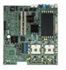
knowledge of the motherboard specifications will also help you avoid mistakes that may damage the board and its components. 1.4.1 Major components The following are the major components of the PR-DLS533 motherboard as pointed out in the picture on page 1-7. 1. DDR DIMM sockets 2. 8-pin 12V SSI - Asus PR-DL | Manual PDF file for PR-DLS533 - Page 21
12 34 5 6 20 19 18 17 16 15 21 7 8 14 13 12 11 10 9 22 27 26 25 24 23 ASUS PR-DLS533 motherboard user guide 1-7 - Asus PR-DL | Manual PDF file for PR-DLS533 - Page 22
processor bus, and integrates the functions of the main memory controller and the Inter Module Bus (IMB) interface unit. The processor interface supports 6 603/604-pin CPU sockets. Two 603/604-pin surface mount, Zero Insertion Force (ZIF) sockets for the Intel® Xeon™ processor with 512KB L2 cache and - Asus PR-DL | Manual PDF file for PR-DLS533 - Page 23
Ethernet controller. This LAN controller provides a 32-bit interface and supports 10/100/1000 Mbps data transfer rates. -or- Intel® 82551QM Fast Ethernet controller. This LAN controller fully supports 10BASE-T/100BASE-TX networking protocols. (optional) ASUS PR-DLS533 motherboard user guide 1-9 - Asus PR-DL | Manual PDF file for PR-DLS533 - Page 24
item 13.) 20 Intel® 82544GC 64-bit PCI-X Gigabit Ethernet controller. This LAN controller is integrated Ethernet LAN component that supports 10/100/1000Mbps data rates. The 82544GC is optimized for LAN on Motherboard (LOM), enterprise networking, and Internet appliances that use a PCI or PCI-X bus - Asus PR-DL | Manual PDF file for PR-DLS533 - Page 25
Chapter 2 This chapter describes the hardware setup procedures that you have to perform when installing system components. It includes details on the switches, jumpers, and connectors on the motherboard. Hardware information - Asus PR-DL | Manual PDF file for PR-DLS533 - Page 26
Chapter summary 2.1 Motherboard installation 2-1 2.2 Motherboard layout 2-2 2.3 Before you proceed 2-3 2.4 Central Processing Unit (CPU 2-3 2.5 System memory 2-8 2.6 Expansion slots 2-11 2.7 Switches and jumpers 2-14 2.8 Connectors 2-18 ASUS PR-DLS533 motherboard - Asus PR-DL | Manual PDF file for PR-DLS533 - Page 27
in the image below. 2.1.2 Screw holes Place 11 screws into the holes indicated by circles to secure the motherboard to the chassis. Do not overtighten the screws! Doing so may damage the motherboard. Place this side towards the rear of the chassis ASUS PR-DLS533 motherboard user guide 2-1 - Asus PR-DL | Manual PDF file for PR-DLS533 - Page 28
2.2 Motherboard layout 33cm ( bit, 184-pin module) CPUFAN1 PARALLEL PORT ® VGA PR-DLS533 RJ-45 (LAN-2) RJ-45 (LAN-1) Intel 82544GC Gigabit Ethernet ServerWorks ® CIOB-X2 I/O IDE SCSI_EN SCSI-A LSI® 53C1030 SCSI Controller 34 SCSI-B 68 IDELED USB2 SYSFAN1 1 35 R452 ASUS ASIC with - Asus PR-DL | Manual PDF file for PR-DLS533 - Page 29
trace cache. Together, these attributes improve system performance by allowing higher core frequencies, faster execution of integer instructions, and data transfer rate of up to 4.27GB/s or 3.2GB/s. Prestonia PR-DLS533 PR-DLS533 Socket 604 Gold Arrow ASUS PR-DLS533 motherboard user guide 2-3 - Asus PR-DL | Manual PDF file for PR-DLS533 - Page 30
you are installing two CPUs, install in the CPU socket 2 first. CPU onboard LED This warning LED (LED1) lights up if you installed two CPUs of different type/voltage. You must install identical CPUs on this motherboard. PR-DLS533 PR-DLS533 Onboard LED LED1 ON CPU Type/Voltage not identical OFF - Asus PR-DL | Manual PDF file for PR-DLS533 - Page 31
the socket to prevent bending the pins and damaging the CPU! 4. When the CPU is in place, press it firmly on the socket while you push down the socket lever to secure the CPU. The lever clicks on the side tab to indicate that it is locked. Marked Corner ASUS PR-DLS533 motherboard user guide 2-5 - Asus PR-DL | Manual PDF file for PR-DLS533 - Page 32
2.4.3 Installing the CPU heatsink and fan The Intel® Xeon™ processors require specially designed heatsink and fan assembly to ensure optimum thermal condition and performance the plastic retention base. (The retention base comes installed with the motherboard.) 2-6 Chapter 2: Hardware information - Asus PR-DL | Manual PDF file for PR-DLS533 - Page 33
Use a small flat screw driver to attach the other end motherboard labeled CPUFAN1 (for the CPU on socket 1) and CPUFAN2 (for the CPU on socket 2). Don't forget to connect the CPU fan cable. Hardware monitoring problems may occur if you fail to plug the cable. ASUS PR-DLS533 motherboard user guide - Asus PR-DL | Manual PDF file for PR-DLS533 - Page 34
Overview The motherboard comes with six Double Data Rate (DDR) Dual Inline Memory Module (DIMM) sockets. These sockets support up to 12GB system memory using 184-pin registered PC2100/1600 DIMMs with Serial Presence Detect (SPD) and Error Check and Correction (ECC). 104 Pins PR-DLS533 PR-DLS533 184 - Asus PR-DL | Manual PDF file for PR-DLS533 - Page 35
Memory (Max. 12GB) = The system chipset only supports Memory frequency/CPU FSB synchronization CPU FSB 533 MHz 400 MHz DDR DIMM Type PC2100 PC1600 Memory Frequency 266 MHz 200 MHz Make sure that the memory frequency matches the CPU FSB (Front Side Bus). ASUS PR-DLS533 motherboard user guide - Asus PR-DL | Manual PDF file for PR-DLS533 - Page 36
motherboard and the components. Follow these steps to install a DIMM. 1. Unlock a DIMM socket by pressing the retaining clips outward. 2. Align a DIMM on the socket to unlock the DIMM. 2. Remove the DIMM from the socket. Support the DIMM lightly with your fingers when pressing the retaining clips - Asus PR-DL | Manual PDF file for PR-DLS533 - Page 37
slots and the expansion cards that they support. Make sure to unplug the power cord before adding or removing expansion cards. Failure to do so may cause you physical injury and damage motherboard . 3. Install the software drivers for the expansion card. ASUS PR-DLS533 motherboard user guide 2-11 - Asus PR-DL | Manual PDF file for PR-DLS533 - Page 38
controller 2 Onboard 82544GC controller 3 Onboard SCSI controller 6 Onboard VGA controller 30 PCI INTB 12 15 18 21 24 27 - - 7 - PCI INTC 13 16 19 22 6 28 - - - - PCI INTD 14 17 20 23 7 29 - - - - When using PCI cards on shared slots, ensure that the drivers support "Share IRQ" or that the - Asus PR-DL | Manual PDF file for PR-DLS533 - Page 39
ZCR (Zero Channel RAID) card. PCI slot (PCI6) PCI6 is a 32-bit/33MHz 5V PCI slot with a Low Pin Count (LPC) signal connector to accommodate the ASUS Server Management Card. This slot has the same specifications regardless of the onboard SCSI controller. ASUS PR-DLS533 motherboard user guide 2-13 - Asus PR-DL | Manual PDF file for PR-DLS533 - Page 40
Switches The following figure shows the location and default settings of the DIP switches on the motherboard. Keep the default settings for stable system operation. PR-DLS533 PR-DLS533 DIP Switches CLKSW ON ON OFF 12345 CONFIG_SW ON ON OFF 12345678 (Default) 1. CPU external frequency - Asus PR-DL | Manual PDF file for PR-DLS533 - Page 41
of the installed CPU. Set to pins 2-3 if you installed a Foster 100MHz CPU. Remove the jumper cap to manually select the CPU frequency using the DIP switches. PR-DLS533 PR-DLS533 CLK Setting CLKSEL 21 32 32 1 Auto Foster Select (Default) by CLKSW ASUS PR-DLS533 motherboard user guide 2-15 - Asus PR-DL | Manual PDF file for PR-DLS533 - Page 42
Ethernet controller. This controller supports up to 1000MBps data rates, and is optimized for LAN On Motherboard (LOM) designs, enterprise networking, and devices that use PCI or PCI-X bus. Set to pins 2-3 to disable the controller. 1G LAN_EN PR-DLS533 PR-DLS533 1G LAN Setting Enable (Default - Asus PR-DL | Manual PDF file for PR-DLS533 - Page 43
during the boot process and enter BIOS setup to re-enter data. Short solder points to Clear CMOS CR2032 3V Lithium Cell CMOS Power R452 ASUS ASIC with Hardware Monitor PR-DLS533 PR-DLS533 Clear RTC RAM ASUS PR-DLS533 motherboard user guide 2-17 - Asus PR-DL | Manual PDF file for PR-DLS533 - Page 44
connector supports the provided floppy drive ribbon cable. After connecting one end to the motherboard, connect the other end to the floppy drive. (Pin 5 is removed to prevent incorrect insertion when using ribbon cables with pin 5 plug). FLOPPY PIN 1 NOTE: Orient the red markings on PR-DLS533 - Asus PR-DL | Manual PDF file for PR-DLS533 - Page 45
the IDE ribbon cable to PIN 1. For UltraDMA/100/66 IDE devices, use an 80-conductor IDE cable. The UltraDMA/66 cable included in the motherboard package also supports UltraDMA/100. ASUS PR-DLS533 motherboard user guide 2-19 - Asus PR-DL | Manual PDF file for PR-DLS533 - Page 46
chassis intrusion detection feature, remove the jumper cap from the pins. CHASSIS +5Volt (Power Supply Stand By) Chassis Signal Ground PR-DLS533 PR-DLS533 Chassis Open Alarm Lead 5. SMBus connector (6-1 pin SMB) This connector allows you to connect SMBus (System Management Bus) devices. Devices - Asus PR-DL | Manual PDF file for PR-DLS533 - Page 47
connectors completely fit. In addition to the 24/20-pin ATXPWR connector, this motherboard requires that you connect the 8-pin ATX +12V power plug to provide 12V 12V 12V 12V PR-DLS533 CON12V PR-DLS533 ATX Power Connector 8-pin GND GND GND GND ASUS PR-DLS533 motherboard user guide 2-21 - Asus PR-DL | Manual PDF file for PR-DLS533 - Page 48
motherboard components. These are not jumpers! DO NOT place jumper caps on the fan connectors! GND +12V Rotation GND +12V Rotation SYSFAN3 CPUFAN1 SYSFAN2 Rotation +12V GND CPUFAN2 SYSFAN1 GND +12V Rotation PR-DLS533 PR-DLS533 supports up to 12 Mbps connection speed. PR-DLS533 PR-DLS533 USB - Asus PR-DL | Manual PDF file for PR-DLS533 - Page 49
Install the ASMC card into the PCI6 slot and connect the cable from the card to this connector. The PCI6 slot on the motherboard has a Low Pin Count (LPC) signal connector to accommodate the ASMC card. ASMC-HE PR-DLS533 PR-DLS533 eRMC Connector ASMC-LE ASUS PR-DLS533 motherboard user guide 2-23 - Asus PR-DL | Manual PDF file for PR-DLS533 - Page 50
card. Connect the 4-pin ASMC interface cable to this connector. IPMIDATA GND IPMICLK NC PR-DLS533 PR-DLS533 IPMI Connector 12. Wake-On-LAN Connector (3-pin WOL_CON) This connector supports a LAN card with a Wake-On-LAN output. The connector powers up the system when a wakeup packet or signal is - Asus PR-DL | Manual PDF file for PR-DLS533 - Page 51
) Channel B Internal SCSI Devices (up to 15 devices) 68-pin Female Terminator 68-pin Internal SCSI Cable (Twisted-Pair Ribbon) Channel A PR-DLS533 Internal SCSI Devices (up to 15 devices) PR-DLS533 SCSI Connection Example 68-pin Female Terminator ASUS PR-DLS533 motherboard user guide 2-25 - Asus PR-DL | Manual PDF file for PR-DLS533 - Page 52
activity LED. The read or write activities of any device connected to the primary or secondary IDE connector cause this LED to light up. PR-DLS533 PR-DLS533 IDE Activity LED IDELED -+ TIP: If the case-mounted LED does not light, try reversing the 2-pin plug. 2-26 Chapter 2: Hardware information - Asus PR-DL | Manual PDF file for PR-DLS533 - Page 53
The LED blinks when data is received. The system message LED feature requires an ACPI OS and driver support. • System Warning Speaker Lead (4-pin SPEAKER) This 4-pin connector is for a chassis-mounted switch to allow use of the keyboard lock feature. ASUS PR-DLS533 motherboard user guide 2-27 - Asus PR-DL | Manual PDF file for PR-DLS533 - Page 54
2-28 Chapter 2: Hardware information - Asus PR-DL | Manual PDF file for PR-DLS533 - Page 55
Chapter 3 This chapter describes the power up sequence and gives information on the BIOS beep codes. Powering up - Asus PR-DL | Manual PDF file for PR-DLS533 - Page 56
Chapter summary 3.1 Starting up for the first time 3-1 3.2 Powering off the computer 3-2 ASUS PR-DLS533 motherboard - Asus PR-DL | Manual PDF file for PR-DLS533 - Page 57
order: a. Monitor b. External SCSI devices (starting with the last Video card not found or video card memory bad CPU overheated; System running at a lower frequency 7. At power on, hold down to enter BIOS Setup. Follow the instructions in Chapter 4. ASUS PR-DLS533 motherboard user guide - Asus PR-DL | Manual PDF file for PR-DLS533 - Page 58
ATX power supplies, you can press the ATX power switch after exiting or shutting down the operating system. If you use Windows 95/98/2000/XP, click the Start button, click Shut Down, then click the OK button to shut down the computer. The power supply should turn off after Windows - Asus PR-DL | Manual PDF file for PR-DLS533 - Page 59
Chapter 4 This chapter tells how to change system settings through the BIOS Setup menus. Detailed descriptions of the BIOS parameters are also provided. BIOS setup - Asus PR-DL | Manual PDF file for PR-DLS533 - Page 60
Chapter summary 4.1 Managing and updating your BIOS 4-1 4.2 BIOS Setup program 4-5 4.3 Main Menu 4-8 4.4 Advanced Menu 4-15 4.5 Power Menu 4-22 4.6 Boot Menu 4-27 4.7 Server Menu 4-30 4.8 Exit Menu 4-31 ASUS PR-DLS533 motherboard - Asus PR-DL | Manual PDF file for PR-DLS533 - Page 61
within Windows, and does not work with certain memory drivers that may be loaded when you boot from Memory:, the memory chip is either not programmable or is not supported by the ACPI BIOS and therefore, cannot be programmed by the Flash Memory Writer utility. ASUS PR-DLS533 motherboard user guide - Asus PR-DL | Manual PDF file for PR-DLS533 - Page 62
5. Select 1. Save Current BIOS to File from the Main menu and press . The Save Current BIOS To File screen appears. 6. Type a filename and the path, for example, A:\XXX-XX.XXX, then press . 4-2 Chapter 4: BIOS Setup - Asus PR-DL | Manual PDF file for PR-DLS533 - Page 63
will solve your problems. Careless updating may result to more problems with the motherboard! 1. Download an updated ASUS BIOS file from the Internet (WWW or FTP) (see ASUS CONTACT INFORMATION on to confirm the BIOS update, press Y to start the update. ASUS PR-DLS533 motherboard user guide 4-3 - Asus PR-DL | Manual PDF file for PR-DLS533 - Page 64
process, and if the problem persists, load the original BIOS file you saved to the boot disk. If the Flash Memory Writer utility is not able to successfully update a complete BIOS file, the system may not boot. If this happens, call the ASUS service center for support. 4-4 Chapter 4: BIOS Setup - Asus PR-DL | Manual PDF file for PR-DLS533 - Page 65
so that the computer can recognize these changes and record them in the CMOS RAM of the Flash ROM. The Flash ROM on the motherboard stores the Setup utility. When you start up the computer, the system and may not exactly match what you see on your screen. ASUS PR-DLS533 motherboard user guide 4-5 - Asus PR-DL | Manual PDF file for PR-DLS533 - Page 66
following table lists the keys found in the legend bar with their corresponding functions. Navigation Key(s) Function Description or Displays the General Help screen from anywhere in the BIOS Setup Jumps to the Exit menu or returns to the main menu from a sub-menu Left or - Asus PR-DL | Manual PDF file for PR-DLS533 - Page 67
to load the Setup default values. While moving around through the Setup program, note that explanations appear in the Item Specific Help window located to the right of each menu. This window displays the help text for the currently highlighted field. ASUS PR-DLS533 motherboard user guide 4-7 - Asus PR-DL | Manual PDF file for PR-DLS533 - Page 68
. Configuration options: [None] [360K, 5.25 in.] [1.2M , 5.25 in.] [720K , 3.5 in.] [1.44M, 3.5 in.] [2.88M, 3.5 in.] Floppy 3 Mode Support [Disabled] This is required to support older Japanese floppy drives. The Floppy 3 Mode feature allows reading and writing of 1.2MB (as opposed to 1.44MB) on - Asus PR-DL | Manual PDF file for PR-DLS533 - Page 69
it by erasing the CMOS Real Time Clock (RTC) RAM. The RAM data containing the password information is powered by the onboard Memory [XXX MB] This field automatically displays the amount of conventional memory detected by the system during the boot process. ASUS PR-DLS533 motherboard user guide - Asus PR-DL | Manual PDF file for PR-DLS533 - Page 70
too new. If the hard disk was already formatted on an older system, Setup may detect incorrect parameters. In these cases, select [User Type HDD] to manually enter the IDE hard disk drive parameters. Refer to the next section for details. Before attempting to configure a hard disk drive, make sure - Asus PR-DL | Manual PDF file for PR-DLS533 - Page 71
[User Type HDD] Manually enter the number of cylinders, heads and sectors per track for the drive. Refer to the drive documentation or on When the Main menu appears, the hard disk drive field displays the size for the hard disk drive that you configured. ASUS PR-DLS533 motherboard user guide 4-11 - Asus PR-DL | Manual PDF file for PR-DLS533 - Page 72
to this field, set the Type field to [User Type HDD] and the Translation Method field to [Manual]. Sector This field configures the number of sectors number of sectors per block to the highest number that the drive supports. Note that when this field is automatically configured, the set value may - Asus PR-DL | Manual PDF file for PR-DLS533 - Page 73
data integrity for compatible IDE devices. Set to [Disabled] to suppress Ultra DMA capability. To make changes to this field, set the Type field to [User Type HDD]. Configuration options: [0] [1] [2] [3] [4] [5] [Disabled] ASUS PR-DLS533 motherboard user guide 4-13 - Asus PR-DL | Manual PDF file for PR-DLS533 - Page 74
Disabled] This field allows you to activate the OS independent keyboard lock function using the keyboard idle timer. You must set a user password or a supervisor password before enabling the keyboard lock function. Configuration options: [Disabled] [1 Min] [2 Mins] [5 Mins] [15 Mins] [30 Mins] 4-14 - Asus PR-DL | Manual PDF file for PR-DLS533 - Page 75
4.4 Advanced Menu CPU Speed [Manual] This field displays the auto- or disable support for Hyper-Threading Technology enabled processors which contain multiple logical processors per physical processor package. . Configuration options: [Enabled] [Auto] ASUS PR-DLS533 motherboard user guide 4-15 - Asus PR-DL | Manual PDF file for PR-DLS533 - Page 76
Memory > 64M [Disabled] When using OS/2 operating systems with installed DRAM of greater than 64MB, you need to set this option to [Enabled]. Otherwise, leave to the default setting [Disabled]. Configuration options: [Disabled] [Enabled] USB Legacy Support [Auto] This motherboard supports Universal - Asus PR-DL | Manual PDF file for PR-DLS533 - Page 77
same type and size) • DIMM sockets DDRA1 and DDRA2 are populated Onboard PCI IDE [Both] You can select to enable the primary IDE channel, both the primary and secondary channels, or disable both channels. Configuration options: [Both] [Primary] [Disabled] ASUS PR-DLS533 motherboard user guide 4-17 - Asus PR-DL | Manual PDF file for PR-DLS533 - Page 78
4.4.2 I/O Device Configuration Floppy Disk Access Control [R/W] When set to [Read Only], this parameter protects files from being copied to floppy disks by allowing reads from, but not writes to, the floppy disk drive. The default setting [R/W] allows both reads and writes. Configuration options: - Asus PR-DL | Manual PDF file for PR-DLS533 - Page 79
channel for the selected ECP mode. This selection is available only if you select [ECP] or [ECP+EPP] in Parallel Port Mode above. Configuration options: [1] [3] ASUS PR-DLS533 motherboard user guide 4-19 - Asus PR-DL | Manual PDF file for PR-DLS533 - Page 80
4.4.3 PCI Configuration Slot 1, Slot 2, Slot 3, Slot 4, Slot 5, Slot 6 IRQ [Auto] These fields set how IRQ use is determined for each PCI slot. The default graphics accelerators or MPEG video cards, may not show colors properly. Setting this field to [Enabled] corrects this problem. If you are - Asus PR-DL | Manual PDF file for PR-DLS533 - Page 81
: [Disabled] [Enabled] Onboard LAN Boot ROM [Disabled] Onboard 2nd LAN Boot ROM [Disabled] When set to [Enabled], these fields allow the system to boot from the network using the onboard LAN controller boot ROM. Configuration options: [Disabled] [Enabled] ASUS PR-DLS533 motherboard user guide 4-21 - Asus PR-DL | Manual PDF file for PR-DLS533 - Page 82
4.5 Power Menu The Power menu allows you to reduce power consumption. This feature turns off the video display and shuts down the hard disk after a period of inactivity. Power Management [User Defined] This field allows you to activate or deactivate the automatic power saving features. When set to - Asus PR-DL | Manual PDF file for PR-DLS533 - Page 83
) feature allows the BIOS to control the video display card if it supports the DPMS feature. [Blank Screen] only period of inactivity as set in this user-configurable field. This feature does not affect SCSI hard drives. Configuration options: [Disabled] [1 ASUS PR-DLS533 motherboard user guide 4-23 - Asus PR-DL | Manual PDF file for PR-DLS533 - Page 84
. Turning an external modem off and then back on while the computer is off causes an initialization string that turns the system power on. Onboard LAN Power Up [Disabled] Power Up on PCI Card [Disabled] These fields allow you to boot your computer from another computer by sending a wake-up frame - Asus PR-DL | Manual PDF file for PR-DLS533 - Page 85
at a certain time of the day by selecting [Everyday] or at a certain time and day by selecting [By Date]. Configuration options: [Disabled] [Everyday] [By Date] ASUS PR-DLS533 motherboard user guide 4-25 - Asus PR-DL | Manual PDF file for PR-DLS533 - Page 86
Monitor MB Temperature [xxxC/xxxF] CPU1 Temperature [xxxC/xxxF] CPU2 Temperature [xxxC/xxxF] The onboard hardware monitor is able to detect the MB (motherboard) and CPU temperatures. Set to [Ignore] only if necessary. CPU1 Fan Speed [xxxxRPM] CPU2 Fan Speed [xxxxRPM] The onboard hardware monitor is - Asus PR-DL | Manual PDF file for PR-DLS533 - Page 87
any device that can boot on an operating system but requires a specific BIOS code for support. Bootable FDDs, ATA HDD, ATAPI CD-ROM, ATA ZIP, and ATA MO drives are classified as BAID. The drives present in the system will appear as options for this field. ASUS PR-DLS533 motherboard user guide 4-27 - Asus PR-DL | Manual PDF file for PR-DLS533 - Page 88
Boot sequence. For this motherboard, the following options are present onboard: [Disabled] [Floppy] [HDD] [CD-ROM] [LAN Option ROM] [SCSI] Plug & Play O/S [No] This field allows you to use a Plug-and-Play (PnP) operating system to configure the PCI bus slots - Asus PR-DL | Manual PDF file for PR-DLS533 - Page 89
Specification 1.4 support. Configuration Slot 1, 2, 3, 4, 5, 6 IRQ [Normal] This field allows you to set the priority level for each expansion slot in order to determine expansion card initialization order. Configuration options: [High] [Normal] [Low] [Skip] ASUS PR-DLS533 motherboard user guide - Asus PR-DL | Manual PDF file for PR-DLS533 - Page 90
4.7 Server Menu DRAM Hot Spare Memory [Disabled] This field allows you to allocate rows of SDRAM for hot spare. Configuration options this field to function. Configuration options: [Disabled] [Enabled] Log Memory ECC Error [Enabled] This field allows you to set whether "Error Checking and Correcting - Asus PR-DL | Manual PDF file for PR-DLS533 - Page 91
this option from the Exit menu to ensure the values you selected are saved to the CMOS RAM. The CMOS RAM is sustained by an onboard backup battery and stays on even when the PC is turned off , and password, the BIOS asks for a confirmation before exiting. ASUS PR-DLS533 motherboard user guide 4-31 - Asus PR-DL | Manual PDF file for PR-DLS533 - Page 92
. Select [Yes] to load default values. Select Exit Saving Changes or make other changes before saving the values to the non-volatile RAM. Discard Changes This option allows you to discard the selections you made and restore the previously saved values. After selecting this option, a confirmation - Asus PR-DL | Manual PDF file for PR-DLS533 - Page 93
Chapter 5 This chapter tells how to install SCSI, LAN, and VGA drivers under various operating systems. Driver installation - Asus PR-DL | Manual PDF file for PR-DLS533 - Page 94
contents 5-1 5.2 Microsoft Windows NT Server 4.0 5-3 5.3 Microsoft Windows 2000 Server 5-13 5.4 Microsoft Windows XP Professional .......... 5-25 5.5 Novell NetWare Server 5-31 5.6 SCO OpenServer 5.0.6a 5-36 5.7 SCO UnixWare Server 5-44 5.8 Linux RedHat 7.3/8.0 5-48 ASUS PR-DLS533 motherboard - Asus PR-DL | Manual PDF file for PR-DLS533 - Page 95
the drivers available for the onboard devices. Follow the installation wizards or find additional instructions as text files in each of the driver folders. 5.1.2 Management Sofware This screen displays the ASUS proprietary server management software. ASUS PR-DLS533 motherboard user guide 5-1 - Asus PR-DL | Manual PDF file for PR-DLS533 - Page 96
5.1.3 Utilities This screen displays the available system utilities that you can install. 5.1.4 Contact This screen displays the ASUS worldwide contact information. 5-2 Chapter 5: Driver installation - Asus PR-DL | Manual PDF file for PR-DLS533 - Page 97
the driver to the registry and copies the driver to the appropriate directory. Choose one of two methods to install these drivers onto a Windows NT 4.0 system. 1. Boot directly from the Windows NT 4.0 CD-ROM -or- 2. Use Windows NT 4.0 Boot Floppy Diskettes. ASUS PR-DLS533 motherboard user guide - Asus PR-DL | Manual PDF file for PR-DLS533 - Page 98
NOTE: If this screen is not displayed as the first user input, then the F6 keypress was not seen by the support disk. 5. Insert the appropriate driver diskette containing the Windows NT driver required to support your LSI Logic adapter(s) and press Enter. 6. "LSI Logic PCI SCSI/FC MPI MiniPort Driver - Asus PR-DL | Manual PDF file for PR-DLS533 - Page 99
load support for the following mass storage devices(s). Press Enter to continue." This message implies that Windows NT recognizes the miniport driver and the SCSI or Fibre Channel hardware. At this point, simply follow the Microsoft Windows NT installation procedure. ASUS PR-DLS533 motherboard user - Asus PR-DL | Manual PDF file for PR-DLS533 - Page 100
NT 4.0 and log on as Administrator. 2. Click on the Start button. Move to Settings-->Control Panel and click. 3. Double click on SCSI Adapters. 4. Click on the Drivers tab. 5. Click Add. A list of installed adapters is displayed. 6. Click the Have Disk button. When prompted, insert the Windows NT - Asus PR-DL | Manual PDF file for PR-DLS533 - Page 101
the utility from the following path: \Drivers\LAN\MAKEDISK\dcreate.exe 3. In the following screen, click on Make Driver Disk. 4. The next screen allows you to select an operating system to install the driver. Select Windows NT 4.0. Refer to the next page. ASUS PR-DLS533 motherboard user guide 5-7 - Asus PR-DL | Manual PDF file for PR-DLS533 - Page 102
5. Insert the floppy disk into the floppy disk drive when prompted. 6. Follow the screen instructions to complete the process. B. New System Installation 1. Double-click the Network icon in the Control Panel to display the Network Setup Wizard. 2. When the Installing - Asus PR-DL | Manual PDF file for PR-DLS533 - Page 103
then click Have Disk... 6. Type A:\ in the dialog box that appears, then click OK. The following screen lists the Intel LAN adapters that you can install. 7. Select Intel(R) PRO/100 Family Adapter, then click OK. Follow the succeeding screen instructions. ASUS PR-DLS533 motherboard user guide 5-9 - Asus PR-DL | Manual PDF file for PR-DLS533 - Page 104
in the dialog box, then click OK. 11. In the following screen, select Intel(R) PRO/1000 Family Adapter, then click OK. Follow the succeeding screen instructions. 12. When done, the following screen appears showing the Intel(R) PRO/1000 Family Adapter in the list. 13. Click Next and follow any other - Asus PR-DL | Manual PDF file for PR-DLS533 - Page 105
that you created from the support CD. Refer to the section "A. Preparing the Intel LAN Driver Disk" if you have not yet created the LAN driver disk. 5. Follow steps 5 to 13 in the section "B. New System Installation" to install the required LAN drivers. ASUS PR-DLS533 motherboard user guide 5-11 - Asus PR-DL | Manual PDF file for PR-DLS533 - Page 106
in enabled in your computer, the following screen appears. Click on ATI Rage XL Display Driver to install the driver. If Autorun is disabled, install the display driver from the following path: \Drivers\ATI\Nt40\Setup.exe 3. Follow the screen instructions to complete the installation. 5-12 Chapter - Asus PR-DL | Manual PDF file for PR-DLS533 - Page 107
registry and copies the driver to the appropriate directory. Choose one of two methods to install these drivers onto a Windows 2000 Server system. 1. Boot directly from the Windows 2000 Server CD-ROM -or- 2. Use Windows 2000 Server Boot Floppy Diskettes ASUS PR-DLS533 motherboard user guide 5-13 - Asus PR-DL | Manual PDF file for PR-DLS533 - Page 108
NOTE: If this screen is not displayed as the first user input, then the F6 keypress was not seen by support disk. 5. Insert the appropriate driver diskette containing the Windows 2000 driver required to support your LSI Logic adapter(s) and press Enter. 6. "LSI Logic PCI SCSI/FC MPI MiniPort Driver - Asus PR-DL | Manual PDF file for PR-DLS533 - Page 109
mass storage devices(s). Press Enter to continue." This message implies that Windows 2000 recognizes the miniport driver and the SCSI or Fibre Channel hardware. At this point, simply follow the Microsoft Windows 2000 Server installation procedure. ASUS PR-DLS533 motherboard user guide 5-15 - Asus PR-DL | Manual PDF file for PR-DLS533 - Page 110
Diskette. 7. Enter or type the path to copy manufacturer's files from A:\. Select OK. The Install Driver menu should have the driver name "LSI Logic PCI SCSI/FC MPI MiniPort Driver" highlighted. 8. If it is not highlighted, select it. Choose OK. At this point, the following message may appear: "The - Asus PR-DL | Manual PDF file for PR-DLS533 - Page 111
14. After rebooting, check the installed SCSI driver from the Computer Management window. 15. Highlight the LSI Logic 1020/1030 Ultra320 SCSI Adapter, click the right mouse button, and select Properties to display the following. ASUS PR-DLS533 motherboard user guide 5-17 - Asus PR-DL | Manual PDF file for PR-DLS533 - Page 112
16. Click Driver Details to display a list of files related to the SCSI driver. 5-18 Chapter 5: Driver installation - Asus PR-DL | Manual PDF file for PR-DLS533 - Page 113
from the following path: \Drivers\LAN\MAKEDISK\dcreate.exe 3. In the following screen, click on Make Driver Disk. 4. The next screen allows you to select an operating system to install the driver. Select Windows 2000 (Gigabit). Refer to the next page. ASUS PR-DLS533 motherboard user guide 5-19 - Asus PR-DL | Manual PDF file for PR-DLS533 - Page 114
disk into the floppy disk drive when prompted. 6. Follow the screen instructions to complete the process. B. Update Driver on an Existing System Installation You may update the LAN driver directly from the support CD. 1. Insert the support CD into the CD-ROM drive. On the screen that appears, click - Asus PR-DL | Manual PDF file for PR-DLS533 - Page 115
installed LAN adapters. 3. Highlight the Intel(R) 82540EM-based Network Connection, click the right mouse button, and select Properties to display the following. 4. Click Driver Details to display a list of the files related to the Intel 82540EM LAN driver. ASUS PR-DLS533 motherboard user guide - Asus PR-DL | Manual PDF file for PR-DLS533 - Page 116
5. Highlight the Intel(R) 82544GC-based Network Connection, click the right mouse button, and select Properties to display the following. 5-22 Chapter 5: Driver installation - Asus PR-DL | Manual PDF file for PR-DLS533 - Page 117
. Select Display a list of the known drivers for this device ... 8. Select Network adapters under Hardware Type, and click Next. 9. Click Have Disk..., then insert the LAN driver disk. 10. Follow the succeeding instructions to complete the installation. ASUS PR-DLS533 motherboard user guide 5-23 - Asus PR-DL | Manual PDF file for PR-DLS533 - Page 118
system installation. You do not need to load any driver for supporting the onboard ATI RAGE XL graphics controller chipset. 5.3.4 Enabling ATA100 Feature in Windows® 2000 To enable the ATA100 feature under Windows 2000, you need to upgrade to Windows 2000 Service Pack 2 or later. 5-24 Chapter - Asus PR-DL | Manual PDF file for PR-DLS533 - Page 119
. Windows XP automatically adds the driver to the registry and copies the driver to the appropriate directory. The method for installing Windows XP on a new system involves using a CD-ROM. Installation using boot floppy diskettes is not supported by Windows XP. ASUS PR-DLS533 motherboard user guide - Asus PR-DL | Manual PDF file for PR-DLS533 - Page 120
Windows XP driver required to support your LSI Logic adapter(s) and press Enter. 5. The screen will display a list of two drivers to select from: "LSI Logic PCI SCSI/FC MPI Driver (XP 32-bit)" "LSI Logic PCI SCSI/FC MPI Driver (XP 64-bit)" Select the driver that matches the processor architecture - Asus PR-DL | Manual PDF file for PR-DLS533 - Page 121
SYMMPI.SYS drivers onto an existing Windows XP system. NOTE: When a LSI Logic SCSI or driver update. In some cases, a message will display saying that this driver has not passed logo testing. This message informs you that a nonsigned driver is being installed. ASUS PR-DLS533 motherboard user guide - Asus PR-DL | Manual PDF file for PR-DLS533 - Page 122
the Finish button to complete the driver upgrade. D. Performance Tuning for Windows XP Windows XP has registry entries that can be used to tune the performance of SCSI I/O for certain configurations. The tunable parameters are large transfer block size support and a guaranteed number of concurrent - Asus PR-DL | Manual PDF file for PR-DLS533 - Page 123
from the following path: \Drivers\LAN\MAKEDISK\dcreate.exe 3. In the following screen, click on Make Driver Disk. 4. The next screen allows you to select an operating system to install the driver. Select Windows XP/64 (Gigabit). Refer to the next page. ASUS PR-DLS533 motherboard user guide 5-29 - Asus PR-DL | Manual PDF file for PR-DLS533 - Page 124
5. Follow the succeeding installation instructions. 6. When done, the following screen appears. Click Finish to complete the installation. 5-30 Chapter 5: Driver installation - Asus PR-DL | Manual PDF file for PR-DLS533 - Page 125
). Press Enter and load an additional driver. Then press the INS key. The system defaults to the A: path. Highlight the LSI Logic NWPA driver and press Enter. Select Yes to save and move the driver into the operating system. Press Enter to copy the files. ASUS PR-DLS533 motherboard user guide 5-31 - Asus PR-DL | Manual PDF file for PR-DLS533 - Page 126
the system prompts the user with the available command line options to load the driver. A description of each driver for every LSI Logic controller SCSI channel or host adapter present in the system. 5. When prompted for a slot number, accept the slot numbers displayed. Make sure to write these slot - Asus PR-DL | Manual PDF file for PR-DLS533 - Page 127
utility from the following path: \Drivers\LAN\MAKEDISK\dcreate.exe 3. In the following screen, click on Make Driver Disk. 4. The next screen allows you to select an operating system to install the driver. Select Novell Netware. Refer to the next page. ASUS PR-DLS533 motherboard user guide 5-33 - Asus PR-DL | Manual PDF file for PR-DLS533 - Page 128
disk drive when prompted. 6. Follow the screen instructions to complete the process. B. NetWare 5.1/6.0 Installations 1. From the NetWare console, type NWCONFIG or Load Install and press . 2. From the Configuration Options screen, choose Driver options and press . 3. Choose Configure - Asus PR-DL | Manual PDF file for PR-DLS533 - Page 129
to return to the server console prompt. 5.5.3 ATI® Rage XL Display Driver Installation You can select the "Super VGA" for the X Server on NetWare 5 server system. The other NetWare system didn't support X Server and you didn't need the VGA driver support. ASUS PR-DLS533 motherboard user guide 5-35 - Asus PR-DL | Manual PDF file for PR-DLS533 - Page 130
system that you are using to create this diskette. See the instructions below for UNIX System and DOS System Users. Locate the SCSI files in the following path in the support CD: \Drivers\SCSI\Fusion-MPT\SCO\1.03.17 For UNIX System Users: Follow these steps to create the BTLD diskette: 1. Insert - Asus PR-DL | Manual PDF file for PR-DLS533 - Page 131
is necessary to build a new UNIX kernel that includes your SDMS driver. During installation, you are given the option of retaining current partitions : unix.safe 2. Install SCSI device support by continuing from "C. Existing System Installation," Step 3. ASUS PR-DLS533 motherboard user guide 5-37 - Asus PR-DL | Manual PDF file for PR-DLS533 - Page 132
to build a new UNIX kernel that includes the proper LSI host adapter driver. The basic steps for accomplishing this are outlined below. For more on UNIX installation, refer to the SCO UNIX System Administrator's Reference Manual. The SCO OpenServer 5 system automatically creates a file unix.safe - Asus PR-DL | Manual PDF file for PR-DLS533 - Page 133
adding a SCSI or Fibre Channel disk drive to this system, go to step 4. 1. At the command prompt, type: mkdev hd Press Enter. 2. The system prompts for the identifier of the host adapter that supports this or press Enter for the default value of zero. ASUS PR-DLS533 motherboard user guide 5-39 - Asus PR-DL | Manual PDF file for PR-DLS533 - Page 134
the default is not correct, type: lsil Press Enter. 6. The system prompts for the host adapter that supports the tape drive. Type the correct host adapter number, and press Enter. If an additional LSI Logic host the host adapter identifier of the preceding step. 5-40 Chapter 5: Driver installation - Asus PR-DL | Manual PDF file for PR-DLS533 - Page 135
system prompts to configure the CD-ROM Drive. Type y and press Enter. 4. The system prompts for the identifier of the host adapter that supports this device. If the default is correct, press Enter. If the default is not correct, type: lsil Press Enter. ASUS PR-DLS533 motherboard user guide 5-41 - Asus PR-DL | Manual PDF file for PR-DLS533 - Page 136
SCO OpenServer 5.0.6a, the system prompts for the bus number of the CD-ROM. Since LSI Logic host adapters support only one bus per adapter, press Enter to get the default of zero, or type 0 (zero) and press ," if you replied y; return to step 3 if you replied n. 5-42 Chapter 5: Driver installation - Asus PR-DL | Manual PDF file for PR-DLS533 - Page 137
the command: reboot Press Enter. 4. After the system reboots and the "boot:" prompt appears, press Enter to load the new kernel. 5. Log in as usual. ASUS PR-DLS533 motherboard user guide 5-43 - Asus PR-DL | Manual PDF file for PR-DLS533 - Page 138
SCSI Driver Installation A. Building the LSI Logic Fusion-MPT™ mpt Driver HBA Diskette This is the guide to create an HBA driver SCSI files in the following path in the support CD: \Drivers\SCSI\Fusion-MPT\Unixware\1.03.17 For UNIX System Users as instructed. For DOS System Users 1. Use - Asus PR-DL | Manual PDF file for PR-DLS533 - Page 139
as instructed. B. driver installation fails. Refer to the section titled Troubleshooting for more information. 3. Once the old kernel is saved, insert the mpt UnixWare driver diskette. 4. Load the driver using the pkgadd command by typing: pkgadd -d diskette1 ASUS PR-DLS533 motherboard user guide - Asus PR-DL | Manual PDF file for PR-DLS533 - Page 140
system will again prompt you to load a driver even if loading was successful. 6. Type q (quit) and press Enter. 7. Verify that the driver is now loaded successfully by typing: pkginfo in the next section titled Troubleshooting. If the reboot is successful, the system is ready to use. 5-46 Chapter - Asus PR-DL | Manual PDF file for PR-DLS533 - Page 141
the system. 5.7.3 ATI® Rage XL Display Driver Installation SCO UnixWare 7.1.1 system can correctly recognize ATI Rage XL graphic controller (ATI MACH64) during installation. User doesn't need to load or modify the video driver for the onboard VGA device. ASUS PR-DLS533 motherboard user guide 5-47 - Asus PR-DL | Manual PDF file for PR-DLS533 - Page 142
with no additional media. For more information on the LSI 53C1030 SCSI controller, refer to the following path in the support CD: \Drivers\SCSI\FUSION-MPT\Linux\2.03.00\mptlinux.txt 5.8.2 Intel® LAN Driver Installation Linux RedHat 7.3/8.0 system can automatically recognize Intel 82551QM/ 82540EM
-
 1
1 -
 2
2 -
 3
3 -
 4
4 -
 5
5 -
 6
6 -
 7
7 -
8
-
9
-
10
-
11
-
12
-
13
-
14
-
15
-
16
-
17
-
18
-
19
-
20
-
21
-
22
-
23
-
24
-
25
-
26
-
27
-
28
-
29
-
30
-
31
-
32
-
33
-
34
-
35
-
36
-
37
-
38
-
39
-
40
-
41
-
42
-
43
-
44
-
45
-
46
-
47
-
48
-
49
-
50
-
51
-
52
-
53
-
54
-
55
-
56
-
57
-
58
-
59
-
60
-
61
-
62
-
63
-
64
-
65
-
66
-
67
-
68
-
69
-
70
-
71
-
72
-
73
-
74
-
75
-
76
-
77
-
78
-
79
-
80
-
81
-
82
-
83
-
84
-
85
-
86
-
87
-
88
-
89
-
90
-
91
-
92
-
93
-
94
-
95
-
96
-
97
-
98
-
99
-
100
-
101
-
102
-
103
-
104
-
105
-
106
-
107
-
108
-
109
-
110
-
111
-
112
-
113
-
114
-
115
-
116
-
117
-
118
-
119
-
120
-
121
-
122
-
123
-
124
-
125
-
126
-
127
-
128
-
129
-
130
-
131
-
132
-
133
-
134
-
135
-
136
-
137
-
138
-
139
-
140
-
141
-
142
 |
 |

Motherboard
PR-DLS533
User Guide