Asus PR-DLS533/Rack Manual PDF file for PR-DLS533
Asus PR-DLS533/Rack Manual
 |
View all Asus PR-DLS533/Rack manuals
Add to My Manuals
Save this manual to your list of manuals |
Asus PR-DLS533/Rack manual content summary:
- Asus PR-DLS533/Rack | Manual PDF file for PR-DLS533 - Page 1
Motherboard PR-DLS533 User Guide - Asus PR-DLS533/Rack | Manual PDF file for PR-DLS533 - Page 2
written permission of ASUSTeK COMPUTER INC. ("ASUS"). Product warranty or service will not be extended if: (1) the product is repaired, modified the serial number of the product is defaced or missing. ASUS PROVIDES THIS MANUAL "AS IS" WITHOUT WARRANTY OF ANY KIND, EITHER EXPRESS OR IMPLIED, - Asus PR-DLS533/Rack | Manual PDF file for PR-DLS533 - Page 3
Features Contents Notices vi Safety information vii About this guide viii How this guide is organized viii Conventions used in this guide ix Where to find more information ix ASUS contact information x PR-DLS533 specifications summary xi Chapter 1: Product introduction 1.1 Welcome 1-1 1.2 - Asus PR-DLS533/Rack | Manual PDF file for PR-DLS533 - Page 4
Safeguards Contents 2.6 Expansion slots 2-11 2.6.1 Installing an expansion card 2-11 2.6.2 Configuring an expansion card 2-11 2.6.3 PCI slots 2-13 2.7 Switches and jumpers 2-14 2.7.1 Switches 2-14 2.7.2 Jumpers 2-15 2.8 Connectors 2-18 Chapter 3: Powering up 3.1 Starting up for the first - Asus PR-DLS533/Rack | Manual PDF file for PR-DLS533 - Page 5
Contents Chapter 5: OS Installation 5.1 Support CD contents 5-1 5.1.1 Drivers 5-1 5.1.2 Management Sofware 5-1 5.1.3 Utilities 5-2 5.1.4 Contact 5-2 5.2 Microsoft® Windows® NT Server 4.0 5-3 5.2.1 LSI® SCSI Driver Installation 5-3 5.2.2 Intel® LAN Driver Installation 5-7 5.2.3 ATI® Rage XL - Asus PR-DLS533/Rack | Manual PDF file for PR-DLS533 - Page 6
. This equipment generates, uses and can radiate radio frequency energy and, if not installed and used in accordance with manufacturer's instructions, may cause harmful interference to radio communications. However, there is no guarantee that interference will not occur in a particular installation - Asus PR-DLS533/Rack | Manual PDF file for PR-DLS533 - Page 7
supply is broken, do not try to fix it by yourself. Contact a qualified service technician or your retailer. Operation safety • Before installing the product and adding devices . • If you encounter technical problems with the product, contact a qualified service technician or your retailer. vii - Asus PR-DLS533/Rack | Manual PDF file for PR-DLS533 - Page 8
How this guide is organized This manual contains the following parts: • Chapter 1: Product introduction This chapter describes the features of the PR-DLS533 motherboard. It includes brief descriptions of the special attributes of the motherboard and the new technology it supports - Asus PR-DLS533/Rack | Manual PDF file for PR-DLS533 - Page 9
Conventions used in this guide To make sure that you perform certain tasks properly, take note of the following symbols used throughout this manual. WARNING: Information to prevent injury to yourself when trying to complete a task. CAUTION: Information to prevent damage to the components when trying - Asus PR-DLS533/Rack | Manual PDF file for PR-DLS533 - Page 10
MB/Others (Tel): +886-2-2890-7121 (English) Notebook (Tel): +886-2-2890-7122 (English) Desktop/Server (Tel): +886-2-2890-7123 (English) Support Fax: +886-2-2890-7698 Support Email: [email protected] Web Site: www.asus.com.tw ASUS COMPUTER INTERNATIONAL (America) Address: 44370 Nobel Drive - Asus PR-DLS533/Rack | Manual PDF file for PR-DLS533 - Page 11
Onboard VGA Expansion slots Rear panel I/O Internal connectors BIOS features Support for Intel® Xeon™ processor On-die 512KB L2 cache RCC 3V (PCI-X1 to PCI-X4) 1 x PCI 64-bit/100MHz 3V (PCI-X5) (PCI-X5 supports either LSI MegaRAID 320-0 or Intel SRC ZCR card when LSI® 53C1030 is onboard) 1 x PCI 32- - Asus PR-DLS533/Rack | Manual PDF file for PR-DLS533 - Page 12
PR-DLS533 specifications summary Form Factor Support CD contents Extended ATX form factor: 12 in x 13 in (30.5 cm x 33 cm) Device drivers Management software Utilities Contact information * Specifications are subject to change without notice. xii - Asus PR-DLS533/Rack | Manual PDF file for PR-DLS533 - Page 13
Chapter 1 This chapter describes the features of the PR-DLS533 motherboard. It includes brief explanations of the special attributes of the motherboard and the new technology it supports. Product introduction - Asus PR-DLS533/Rack | Manual PDF file for PR-DLS533 - Page 14
Chapter summary 1.1 Welcome 1-1 1.2 Package contents 1-1 1.3 Special features 1-2 1.4 Motherboard overview 1-6 ASUS PR-DLS533 motherboard - Asus PR-DLS533/Rack | Manual PDF file for PR-DLS533 - Page 15
factor: 12 in x 13 in (30.5 cm x 33 cm) ASUS PR-DLS533 support CD I/O shield 80-conductor ribbon cable for UltraDMA100/66//33 IDE drives 68-pin LVD drive Bag of extra jumper caps PR-DLS533 User Guide LSI SCSI Controller User's Manual If any of the above items is damaged or missing, contact - Asus PR-DLS533/Rack | Manual PDF file for PR-DLS533 - Page 16
, and Internet applications. See page 2-10. Dual-channel Ultra320 SCSI The LSI® 53C1030 64-bit/100MHz PCI-X SCSI controller is onboard to support dual-channel Ultra320 SCSI connectors that provide high-speed data transfer interfaces. Advanced 64-bit PCI-X slots The 64-bit/133MHz PCI-X slots onboard - Asus PR-DLS533/Rack | Manual PDF file for PR-DLS533 - Page 17
The motherboard comes with the Intel® 82540EM 32-bit PCI Gigabit Ethernet controller and the Intel® 82544GC 64-bit PCI-X Gigabit Ethernet controller to support the latest LAN technologies. The Intel® 82551QM Fast Ethernet controller is an option. Onboard VGA The ATI Rage-XL PCI-based VGA controller - Asus PR-DLS533/Rack | Manual PDF file for PR-DLS533 - Page 18
management The motherboard comes with an ASMC connector that supports the optional ASMC-HE/ME/LE card to comply with server reliability, availability, and serviceability requirements. Remote management response via remote diagnostics and troubleshooting still works even when the operating system has - Asus PR-DLS533/Rack | Manual PDF file for PR-DLS533 - Page 19
mode. This feature reduces both power consumption and system noise. Chassis intrusion detection The motherboard supports chassis intrusion monitoring through the ASUS ASIC. A chassis intrusion event is retained in the required by the PC '99 specification. ASUS PR-DLS533 motherboard user guide 1-5 - Asus PR-DLS533/Rack | Manual PDF file for PR-DLS533 - Page 20
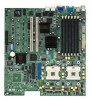
1.4 Motherboard overview Before you install the PR-DLS533 motherboard, familiarize yourself with its physical configuration and available features to facilitate the motherboard installation and future upgrades. A sufficient knowledge of the motherboard specifications will also help you avoid - Asus PR-DLS533/Rack | Manual PDF file for PR-DLS533 - Page 21
12 34 5 6 20 19 18 17 16 15 21 7 8 14 13 12 11 10 9 22 27 26 25 24 23 ASUS PR-DLS533 motherboard user guide 1-7 - Asus PR-DLS533/Rack | Manual PDF file for PR-DLS533 - Page 22
533/400 MHz system bus that allows up to 4.26GB/s or 3.2GB/s data transfer rate. 7 IDE connectors. These dual-channel bus master IDE connectors support up to four Ultra DMA/100/66, PIO Modes 3 & 4 IDE devices. Both the primary (blue) and secondary (black) connectors are slotted to prevent incorrect - Asus PR-DLS533/Rack | Manual PDF file for PR-DLS533 - Page 23
supports supports multiple PCI-X interfaces that allows large, efficient, and flexible I/O configurations. The CIOB-X2 supports controller supports up support bus master PCI supports 10/100/1000 Mbps data transfer rates. -or- Intel® 82551QM Fast Ethernet controller. This LAN controller fully supports - Asus PR-DLS533/Rack | Manual PDF file for PR-DLS533 - Page 24
), enterprise networking, and Internet appliances that use a PCI or PCI-X bus. The controller provides a 32/64-bit 33/66MHz interface to the PCI bus that supports PCI Specification Rev. 2.2, and to the PCI-X extension to the PCI Local Bus Rev. 1.0a at clock rates of up to 133MHz. 21 PS/2 mouse - Asus PR-DLS533/Rack | Manual PDF file for PR-DLS533 - Page 25
Chapter 2 This chapter describes the hardware setup procedures that you have to perform when installing system components. It includes details on the switches, jumpers, and connectors on the motherboard. Hardware information - Asus PR-DLS533/Rack | Manual PDF file for PR-DLS533 - Page 26
Chapter summary 2.1 Motherboard installation 2-1 2.2 Motherboard layout 2-2 2.3 Before you proceed 2-3 2.4 Central Processing Unit (CPU 2-3 2.5 System memory 2-8 2.6 Expansion slots 2-11 2.7 Switches and jumpers 2-14 2.8 Connectors 2-18 ASUS PR-DLS533 motherboard - Asus PR-DLS533/Rack | Manual PDF file for PR-DLS533 - Page 27
. Do not overtighten the screws! Doing so may damage the motherboard. Place this side towards the rear of the chassis ASUS PR-DLS533 motherboard user guide 2-1 - Asus PR-DLS533/Rack | Manual PDF file for PR-DLS533 - Page 28
2.2 Motherboard layout 33cm (13in) PS/2 T: Mouse B: Keyboard SYSFAN3 USB1 USB2 COM1 CON12V ATX_POWER DDR DIMMA1 (64/72 bit, 184-pin module) DDR DIMMA2 (64/72 bit, 184-pin module) DDR DIMMB1 (64/72 bit, 184-pin module) DDR DIMMB2 (64/72 bit, 184-pin module) DDR DIMMC1 (64/72 bit, 184-pin - Asus PR-DLS533/Rack | Manual PDF file for PR-DLS533 - Page 29
system bus, and execution trace cache. Together, these attributes improve system performance by allowing higher core frequencies, faster execution of integer instructions, and data transfer rate of up to 4.27GB/s or 3.2GB/s. Prestonia PR-DLS533 PR-DLS533 Socket 604 Gold Arrow ASUS PR-DLS533 - Asus PR-DLS533/Rack | Manual PDF file for PR-DLS533 - Page 30
of the CPU into the socket may bend the pins and severely damage the CPU! CPU Socket 1 (outer socket) CPU Socket 2 (inner socket) 1. The motherboard supports either one or two CPUs. If you are installing only one CPU, you MUST install it in CPU socket 1. 2. If you are installing two CPUs - Asus PR-DLS533/Rack | Manual PDF file for PR-DLS533 - Page 31
lever to secure the CPU. The lever clicks on the side tab to indicate that it is locked. Marked Corner ASUS PR-DLS533 motherboard user guide 2-5 - Asus PR-DLS533/Rack | Manual PDF file for PR-DLS533 - Page 32
2.4.3 Installing the CPU heatsink and fan The Intel® Xeon™ processors require specially designed heatsink and fan assembly to ensure optimum thermal condition and performance. Follow these steps to install the CPU heatsink and fan. 1. Place the heatsink and fan assembly on top of the installed CPU, - Asus PR-DLS533/Rack | Manual PDF file for PR-DLS533 - Page 33
motherboard labeled CPUFAN1 (for the CPU on socket 1) and CPUFAN2 (for the CPU on socket 2). Don't forget to connect the CPU fan cable. Hardware monitoring problems may occur if you fail to plug the cable. ASUS PR-DLS533 motherboard user - Asus PR-DLS533/Rack | Manual PDF file for PR-DLS533 - Page 34
operations in one clock cycle, thus providing twice the throughput of SDR memory. For example, a 200MHz DDR DIMM will support a 100MHz memory bus, and a 266MHz DDR DIMM will support a 133MHz memory bus. DDR Data Transfer Rate 266MHz 200MHz DDR Base Frequency 133MHz 100MHz A DDR DIMM has the same - Asus PR-DLS533/Rack | Manual PDF file for PR-DLS533 - Page 35
128MB, 256MB, 512MB, 1GB, 2GB x1 Total System Memory (Max. 12GB) = The system chipset only supports PC2100/1600 registered ECC DIMMs. Make sure to use only the specified DIMM types for stable system operation. Memory the CPU FSB (Front Side Bus). ASUS PR-DLS533 motherboard user guide 2-9 - Asus PR-DLS533/Rack | Manual PDF file for PR-DLS533 - Page 36
a DIMM Follow these steps to remove a DIMM. 1. Simultaneously press the retaining clips outward to unlock the DIMM. 2. Remove the DIMM from the socket. Support the DIMM lightly with your fingers when pressing the retaining clips. The DIMM might get damaged when it flips out with extra force. 2-10 - Asus PR-DLS533/Rack | Manual PDF file for PR-DLS533 - Page 37
need to install expansion cards. The following subsections describe the slots and the expansion cards that they support. Make sure to unplug the power cord before adding or removing expansion cards. Failure to do so software drivers for the expansion card. ASUS PR-DLS533 motherboard user guide 2-11 - Asus PR-DLS533/Rack | Manual PDF file for PR-DLS533 - Page 38
- - 7 - PCI INTC 13 16 19 22 6 28 - - - - PCI INTD 14 17 20 23 7 29 - - - - When using PCI cards on shared slots, ensure that the drivers support "Share IRQ" or that the cards do not need IRQ assignments. Otherwise, conflicts will arise between the two PCI groups, making the system unstable and - Asus PR-DLS533/Rack | Manual PDF file for PR-DLS533 - Page 39
bus speeds to 100MHz for both cards. Plugging in three cards allows for 66MHz for all three cards. ** PCI-X5 supports the LSI MegaRAID 320-0 or Intel SRC ZCR (Zero Channel RAID) card. PCI slot (PCI6) PCI6 is a regardless of the onboard SCSI controller. ASUS PR-DLS533 motherboard user guide 2-13 - Asus PR-DLS533/Rack | Manual PDF file for PR-DLS533 - Page 40
2.7 Switches and jumpers 2.7.1 Switches The following figure shows the location and default settings of the DIP switches on the motherboard. Keep the default settings for stable system operation. PR-DLS533 PR-DLS533 DIP Switches CLKSW ON ON OFF 12345 CONFIG_SW ON ON OFF 12345678 (Default - Asus PR-DLS533/Rack | Manual PDF file for PR-DLS533 - Page 41
frequency selection depending on the type of the installed CPU. Set to pins 2-3 if you installed a Foster 100MHz CPU. Remove the jumper cap to manually select the CPU frequency using the DIP switches. PR-DLS533 PR-DLS533 CLK Setting CLKSEL 21 32 32 1 Auto Foster Select (Default) by CLKSW - Asus PR-DLS533/Rack | Manual PDF file for PR-DLS533 - Page 42
Gigabit Ethernet setting (3-pin 1G LAN_EN) Set this jumper to pins 1-2 to enable the onboard Intel® 82544GC Gigabit Ethernet controller. This controller supports up to 1000MBps data rates, and is optimized for LAN On Motherboard (LOM) designs, enterprise networking, and devices that use PCI or PCI - Asus PR-DLS533/Rack | Manual PDF file for PR-DLS533 - Page 43
CMOS CR2032 3V Lithium Cell CMOS Power R452 ASUS ASIC with Hardware Monitor PR-DLS533 PR-DLS533 Clear RTC RAM ASUS PR-DLS533 motherboard user guide 2-17 - Asus PR-DLS533/Rack | Manual PDF file for PR-DLS533 - Page 44
and CD-ROM drives, but may be on the opposite side on floppy disk drives. 1. Floppy disk drive connector (34-1 pin FLOPPY) This connector supports the provided floppy drive ribbon cable. After connecting one end to the motherboard, connect the other end to the floppy drive. (Pin 5 is removed to - Asus PR-DLS533/Rack | Manual PDF file for PR-DLS533 - Page 45
its jumper accordingly. Refer to the hard disk documentation for the jumper settings. BIOS supports specific device bootup. If you have more than two UltraDMA/100/66 devices, purchase cable included in the motherboard package also supports UltraDMA/100. ASUS PR-DLS533 motherboard user guide 2-19 - Asus PR-DLS533/Rack | Manual PDF file for PR-DLS533 - Page 46
4. Chassis alarm lead (4-1 pin CHASSIS) This lead is for a chassis designed with intrusion detection feature. This requires an external detection mechanism such as a chassis intrusion sensor or microswitch. When you remove any chassis component, the sensor triggers and sends a high-level signal to - Asus PR-DLS533/Rack | Manual PDF file for PR-DLS533 - Page 47
-pin Power Connector 12V 12V 12V 12V PR-DLS533 CON12V PR-DLS533 ATX Power Connector 8-pin GND GND GND GND ASUS PR-DLS533 motherboard user guide 2-21 - Asus PR-DLS533/Rack | Manual PDF file for PR-DLS533 - Page 48
the USB ports on the rear panel are inadequate, a USB header is available for additional USB ports. The USB header complies with USB 1.1 specification that supports up to 12 Mbps connection speed. PR-DLS533 PR-DLS533 USB Header USB2 6 USB Power USBP3- USBP3+ GND 10 1 USB Power USBP2- USBP2+ GND - Asus PR-DLS533/Rack | Manual PDF file for PR-DLS533 - Page 49
-0 or the Intel SRC ZCR (Zero-Channel RAID) card to provide advanced RAID functionality. The card supports RAID levels 0, 1, 5, multilevel 0/1 and 0/5, cache memory modules with ECC, and predictive caching capability PR-DLS533 eRMC Connector ASMC-LE ASUS PR-DLS533 motherboard user guide 2-23 - Asus PR-DLS533/Rack | Manual PDF file for PR-DLS533 - Page 50
interface cable to this connector. IPMIDATA GND IPMICLK NC PR-DLS533 PR-DLS533 IPMI Connector 12. Wake-On-LAN Connector (3-pin WOL_CON) This connector supports a LAN card with a Wake-On-LAN output. The connector powers up the system when a wakeup packet or signal is received through the LAN card - Asus PR-DLS533/Rack | Manual PDF file for PR-DLS533 - Page 51
for each of the two channels. The onboard SCSI chipset incorporates an advanced multimode I/O cell that supports both single-ended (SE), Ultra2, Ultra160, and Ultra320 devices. With Ultra320 devices, the SCSI Connection Example 68-pin Female Terminator ASUS PR-DLS533 motherboard user guide 2-25 - Asus PR-DLS533/Rack | Manual PDF file for PR-DLS533 - Page 52
14. Wake-On-Ring Connector (2-pin WOR) This connector connects to internal modem cards with a Wake-OnRing output. The connector powers up the system when a ringup packet or signal is received through the internal modem card. For external modems, Wake-On-Ring is detected through the COM port. WOR 1 - Asus PR-DLS533/Rack | Manual PDF file for PR-DLS533 - Page 53
. The LED blinks when data is received. The system message LED feature requires an ACPI OS and driver support. • System Warning Speaker Lead (4-pin SPEAKER) This 4-pin connector is for a chassis-mounted speaker. • allow use of the keyboard lock feature. ASUS PR-DLS533 motherboard user guide 2-27 - Asus PR-DLS533/Rack | Manual PDF file for PR-DLS533 - Page 54
2-28 Chapter 2: Hardware information - Asus PR-DLS533/Rack | Manual PDF file for PR-DLS533 - Page 55
Chapter 3 This chapter describes the power up sequence and gives information on the BIOS beep codes. Powering up - Asus PR-DLS533/Rack | Manual PDF file for PR-DLS533 - Page 56
Chapter summary 3.1 Starting up for the first time 3-1 3.2 Powering off the computer 3-2 ASUS PR-DLS533 motherboard - Asus PR-DLS533/Rack | Manual PDF file for PR-DLS533 - Page 57
found or video card memory bad CPU overheated; System running at a lower frequency 7. At power on, hold down to enter BIOS Setup. Follow the instructions in Chapter 4. ASUS PR-DLS533 motherboard user - Asus PR-DLS533/Rack | Manual PDF file for PR-DLS533 - Page 58
3.2 Powering off the computer You must first exit the operating system and shut down the system before switching off the power. For ATX power supplies, you can press the ATX power switch after exiting or shutting down the operating system. If you use Windows 95/98/2000/XP, click the Start button, - Asus PR-DLS533/Rack | Manual PDF file for PR-DLS533 - Page 59
Chapter 4 This chapter tells how to change system settings through the BIOS Setup menus. Detailed descriptions of the BIOS parameters are also provided. BIOS setup - Asus PR-DLS533/Rack | Manual PDF file for PR-DLS533 - Page 60
Chapter summary 4.1 Managing and updating your BIOS 4-1 4.2 BIOS Setup program 4-5 4.3 Main Menu 4-8 4.4 Advanced Menu 4-15 4.5 Power Menu 4-22 4.6 Boot Menu 4-27 4.7 Server Menu 4-30 4.8 Exit Menu 4-31 ASUS PR-DLS533 motherboard - Asus PR-DLS533/Rack | Manual PDF file for PR-DLS533 - Page 61
mode, type A:\AFLASH to run AFLASH. If the word "unknown" appears after Flash Memory:, the memory chip is either not programmable or is not supported by the ACPI BIOS and therefore, cannot be programmed by the Flash Memory Writer utility. ASUS PR-DLS533 motherboard user - Asus PR-DLS533/Rack | Manual PDF file for PR-DLS533 - Page 62
5. Select 1. Save Current BIOS to File from the Main menu and press . The Save Current BIOS To File screen appears. 6. Type a filename and the path, for example, A:\XXX-XX.XXX, then press . 4-2 Chapter 4: BIOS Setup - Asus PR-DLS533/Rack | Manual PDF file for PR-DLS533 - Page 63
the motherboard and you are sure that the new BIOS revision will solve your problems. Careless updating may result to more problems with the motherboard! 1. Download an updated ASUS BIOS file from the Internet ( BIOS update, press Y to start the update. ASUS PR-DLS533 motherboard user guide 4-3 - Asus PR-DLS533/Rack | Manual PDF file for PR-DLS533 - Page 64
process, and if the problem persists, load the original BIOS file you saved to the boot disk. If the Flash Memory Writer utility is not able to successfully update a complete BIOS file, the system may not boot. If this happens, call the ASUS service center for support. 4-4 Chapter 4: BIOS Setup - Asus PR-DLS533/Rack | Manual PDF file for PR-DLS533 - Page 65
4.2 BIOS Setup program This motherboard supports a programmable Flash ROM that you can update using the provided utility described in section "4.1 Managing and updating your BIOS." purposes only, and may not exactly match what you see on your screen. ASUS PR-DLS533 motherboard user guide 4-5 - Asus PR-DLS533/Rack | Manual PDF file for PR-DLS533 - Page 66
4.2.1 BIOS menu bar The top of the screen has a menu bar with the following selections: MAIN Use this menu to make changes to the basic system configuration. ADVANCED Use this menu to enable and make changes to the advanced features. POWER Use this menu to configure power management features. - Asus PR-DLS533/Rack | Manual PDF file for PR-DLS533 - Page 67
Help window located to the right of each menu. This window displays the help text for the currently highlighted field. ASUS PR-DLS533 motherboard user guide 4-7 - Asus PR-DLS533/Rack | Manual PDF file for PR-DLS533 - Page 68
. Configuration options: [None] [360K, 5.25 in.] [1.2M , 5.25 in.] [720K , 3.5 in.] [1.44M, 3.5 in.] [2.88M, 3.5 in.] Floppy 3 Mode Support [Disabled] This is required to support older Japanese floppy drives. The Floppy 3 Mode feature allows reading and writing of 1.2MB (as opposed to 1.44MB) on - Asus PR-DLS533/Rack | Manual PDF file for PR-DLS533 - Page 69
Memory [XXX MB] This field automatically displays the amount of conventional memory detected by the system during the boot process. ASUS PR-DLS533 motherboard user guide 4-9 - Asus PR-DLS533/Rack | Manual PDF file for PR-DLS533 - Page 70
. If the hard disk was already formatted on an older system, Setup may detect incorrect parameters. In these cases, select [User Type HDD] to manually enter the IDE hard disk drive parameters. Refer to the next section for details. Before attempting to configure a hard disk drive, make sure you have - Asus PR-DLS533/Rack | Manual PDF file for PR-DLS533 - Page 71
[User Type HDD] Manually enter the number of cylinders, heads and sectors per track for the drive. Refer to the drive documentation or on the drive label appears, the hard disk drive field displays the size for the hard disk drive that you configured. ASUS PR-DLS533 motherboard user guide 4-11 - Asus PR-DLS533/Rack | Manual PDF file for PR-DLS533 - Page 72
Type field to [User Type HDD] and the Translation Method field to [Manual]. CHS Capacity This field shows the drive's maximum CHS capacity as calculated by number of sectors per block to the highest number that the drive supports. Note that when this field is automatically configured, the set value - Asus PR-DLS533/Rack | Manual PDF file for PR-DLS533 - Page 73
Ultra DMA capability. To make changes to this field, set the Type field to [User Type HDD]. Configuration options: [0] [1] [2] [3] [4] [5] [Disabled] ASUS PR-DLS533 motherboard user guide 4-13 - Asus PR-DLS533/Rack | Manual PDF file for PR-DLS533 - Page 74
4.3.2 Keyboard Features Boot Up NumLock Status [On] This field enables users to activate the Number Lock function upon system boot. Configuration options: [Off] [On] Keyboard Auto-Repeat Rate [6/Sec] This controls the speed at which the system registers repeated keystrokes. Options range from 6 to - Asus PR-DLS533/Rack | Manual PDF file for PR-DLS533 - Page 75
4.4 Advanced Menu CPU Speed [Manual] This field displays the auto-detected CPU speed. CPU [Enabled] This item allows you to enable or disable support for Hyper-Threading Technology enabled processors which contain multiple logical : [Enabled] [Auto] ASUS PR-DLS533 motherboard user guide 4-15 - Asus PR-DLS533/Rack | Manual PDF file for PR-DLS533 - Page 76
need to set this option to [Enabled]. Otherwise, leave to the default setting [Disabled]. Configuration options: [Disabled] [Enabled] USB Legacy Support [Auto] This motherboard supports Universal Serial Bus (USB) devices. The default of [Auto] allows the system to detect a USB device at startup. If - Asus PR-DLS533/Rack | Manual PDF file for PR-DLS533 - Page 77
by caching the display data. You must set this to UC (uncacheable) if your display card cannot support this feature; otherwise your system may not boot. Configuration options: [UC] [USWC] Enhanced Memory Mapping options: [Both] [Primary] [Disabled] ASUS PR-DLS533 motherboard user guide 4-17 - Asus PR-DLS533/Rack | Manual PDF file for PR-DLS533 - Page 78
4.4.2 I/O Device Configuration Floppy Disk Access Control [R/W] When set to [Read Only], this parameter protects files from being copied to floppy disks by allowing reads from, but not writes to, the floppy disk drive. The default setting [R/W] allows both reads and writes. Configuration options: - Asus PR-DLS533/Rack | Manual PDF file for PR-DLS533 - Page 79
mode. This selection is available only if you select [ECP] or [ECP+EPP] in Parallel Port Mode above. Configuration options: [1] [3] ASUS PR-DLS533 motherboard user guide 4-19 - Asus PR-DLS533/Rack | Manual PDF file for PR-DLS533 - Page 80
-standard VGA cards, like graphics accelerators or MPEG video cards, may not show colors properly. Setting this field to [Enabled] corrects this problem. If you are using standard VGA cards, leave this field to the default setting [Disabled]. Configuration options: [Disabled] [Enabled] PCI Latency - Asus PR-DLS533/Rack | Manual PDF file for PR-DLS533 - Page 81
fields allow the system to boot from the network using the onboard LAN controller boot ROM. Configuration options: [Disabled] [Enabled] ASUS PR-DLS533 motherboard user guide 4-21 - Asus PR-DLS533/Rack | Manual PDF file for PR-DLS533 - Page 82
4.5 Power Menu The Power menu allows you to reduce power consumption. This feature turns off the video display and shuts down the hard disk after a period of inactivity. Power Management [User Defined] This field allows you to activate or deactivate the automatic power saving features. When set to - Asus PR-DLS533/Rack | Manual PDF file for PR-DLS533 - Page 83
Power Management System (DPMS) feature allows the BIOS to control the video display card if it supports the DPMS feature. [Blank Screen] only blanks the screen. Use this for monitors without power management . Configuration options: [Soft off] [Suspend] ASUS PR-DLS533 motherboard user guide 4-23 - Asus PR-DLS533/Rack | Manual PDF file for PR-DLS533 - Page 84
4.5.1 Power Up Control AC PWR Loss Restart [Disabled] This allows you to set whether or not to reboot the system after power interruptions. [Disabled] leaves your system off while [Enabled] reboots the system. [Previous State] sets the system back to the state it was before the power interruption. - Asus PR-DLS533/Rack | Manual PDF file for PR-DLS533 - Page 85
day by selecting [Everyday] or at a certain time and day by selecting [By Date]. Configuration options: [Disabled] [Everyday] [By Date] ASUS PR-DLS533 motherboard user guide 4-25 - Asus PR-DLS533/Rack | Manual PDF file for PR-DLS533 - Page 86
4.5.2 Hardware Monitor MB Temperature [xxxC/xxxF] CPU1 Temperature [xxxC/xxxF] CPU2 Temperature [xxxC/xxxF] The onboard hardware monitor is able to detect the MB (motherboard) and CPU temperatures. Set to [Ignore] only if necessary. CPU1 Fan Speed [xxxxRPM] CPU2 Fan Speed [xxxxRPM] The onboard - Asus PR-DLS533/Rack | Manual PDF file for PR-DLS533 - Page 87
4.6 Boot Menu The motherboard BIOS supports the BIOS Boot Specification (BBS) version 1.01. BBS is from. A BAID is any device that can boot on an operating system but requires a specific BIOS code for support. Bootable FDDs, ATA HDD, ATAPI CD-ROM, ATA ZIP, and ATA MO drives are classified as BAID. - Asus PR-DLS533/Rack | Manual PDF file for PR-DLS533 - Page 88
2nd Boot : (BCV) [None] This field allows you to select a Boot Connection Vector (BCV) device to boot from. BCV devices include SCSI controllers or SCSI cards, RAID cards, and other devices on add-on cards with option ROM that hooks INT 13 to BIOS. Some SCSI RAID cards hook INT19 to BIOS. If you use - Asus PR-DLS533/Rack | Manual PDF file for PR-DLS533 - Page 89
] This field allows you to enable or disable the MultiProcessor Specification 1.4 support. Configuration options: [Disabled] [Enabled] Quick Power On Self Test [Enabled] This field speeds up the order. Configuration options: [High] [Normal] [Low] [Skip] ASUS PR-DLS533 motherboard user guide 4-29 - Asus PR-DLS533/Rack | Manual PDF file for PR-DLS533 - Page 90
4.7 Server Menu DRAM Hot Spare Memory [Disabled] This field allows you to allocate rows of SDRAM for hot spare. Configuration options: [Disabled] [1 row] [2 rows] [3 rows] Remote Console [Disabled] This field allows the text mode VGA display to be sent out to VT100 terminal through COM1. This - Asus PR-DLS533/Rack | Manual PDF file for PR-DLS533 - Page 91
you made changes to fields other than system date, system time, and password, the BIOS asks for a confirmation before exiting. ASUS PR-DLS533 motherboard user guide 4-31 - Asus PR-DLS533/Rack | Manual PDF file for PR-DLS533 - Page 92
Load Setup Defaults This option allows you to load the default values for each of the parameters on the Setup menus. When you select this option or if you press , a confirmation window appears. Select [Yes] to load default values. Select Exit Saving Changes or make other changes before saving - Asus PR-DLS533/Rack | Manual PDF file for PR-DLS533 - Page 93
Chapter 5 This chapter tells how to install SCSI, LAN, and VGA drivers under various operating systems. Driver installation - Asus PR-DLS533/Rack | Manual PDF file for PR-DLS533 - Page 94
Chapter summary 5.1 Support CD contents 5-1 5.2 Microsoft Windows NT Server 4.0 5-3 5.3 Microsoft Windows 2000 Server 5-13 5.4 Microsoft Windows XP Professional .......... 5-25 5.5 Novell NetWare Server 5-31 5.6 SCO OpenServer 5.0.6a 5-36 5.7 SCO - Asus PR-DLS533/Rack | Manual PDF file for PR-DLS533 - Page 95
the motherboard features. To begin using the support CD, simply insert the CD into your CD NOT enabled in your computer, browse the contents of the support CD to locate the file ASSETUP.EXE from the BIN folder Follow the installation wizards or find additional instructions as text files in each of - Asus PR-DLS533/Rack | Manual PDF file for PR-DLS533 - Page 96
5.1.3 Utilities This screen displays the available system utilities that you can install. 5.1.4 Contact This screen displays the ASUS worldwide contact information. 5-2 Chapter 5: Driver installation - Asus PR-DLS533/Rack | Manual PDF file for PR-DLS533 - Page 97
for the new SCSI controllers, you must load the driver manually prior to Windows NT 4.0 installation. A. Preparing an LSI Driver Disk From the support CD, locate the LSI drivers in the following path: -ROM -or- 2. Use Windows NT 4.0 Boot Floppy Diskettes. ASUS PR-DLS533 motherboard user guide 5-3 - Asus PR-DLS533/Rack | Manual PDF file for PR-DLS533 - Page 98
a driver diskette. IMPORTANT: Read Steps 2 and 3 before performing the instructions contained within these steps. 2. Start the Windows NT 4.0 installation by booting from the Windows NT CD-ROM: The system BIOS must support booting from a CD-ROM. BIOS settings may need to be changed - Asus PR-DLS533/Rack | Manual PDF file for PR-DLS533 - Page 99
IMPORTANT: Read Step 2 before performing the instructions contained within this step. 2. Start the S to skip automatic detection and do manual selection. A screen displays the message " screen displays the message "Setup will load support for the following mass storage devices(s). Press guide 5-5 - Asus PR-DLS533/Rack | Manual PDF file for PR-DLS533 - Page 100
C. Existing System Installation To install the SYMMPI.SYS miniport driver, follow these steps: 1. Boot Windows NT 4.0 and log on as Administrator. 2. Click on the Start button. Move to Settings-->Control Panel and click. 3. Double click on SCSI Adapters. 4. Click on the Drivers tab. 5. Click Add. A - Asus PR-DLS533/Rack | Manual PDF file for PR-DLS533 - Page 101
Windows NT 4.0, copy the LAN drivers from the support CD into a floppy disk. Prepare one blank formatted high density floppy disk before proceeding. 1. Insert the support CD into the CD-ROM drive. 2. Run the Select Windows NT 4.0. Refer to the next page. ASUS PR-DLS533 motherboard user guide 5-7 - Asus PR-DLS533/Rack | Manual PDF file for PR-DLS533 - Page 102
5. Insert the floppy disk into the floppy disk drive when prompted. 6. Follow the screen instructions to complete the process. B. New System Installation 1. Double-click the Network icon in the Control Panel to display the Network Setup Wizard. 2. When the Installing - Asus PR-DLS533/Rack | Manual PDF file for PR-DLS533 - Page 103
. The following screen lists the Intel LAN adapters that you can install. 7. Select Intel(R) PRO/100 Family Adapter, then click OK. Follow the succeeding screen instructions. ASUS PR-DLS533 motherboard user guide 5-9 - Asus PR-DLS533/Rack | Manual PDF file for PR-DLS533 - Page 104
in the dialog box, then click OK. 11. In the following screen, select Intel(R) PRO/1000 Family Adapter, then click OK. Follow the succeeding screen instructions. 12. When done, the following screen appears showing the Intel(R) PRO/1000 Family Adapter in the list. 13. Click Next and follow any other - Asus PR-DLS533/Rack | Manual PDF file for PR-DLS533 - Page 105
click Add. A list of adapters appears. 4. Do not select an adapter from the list. Instead, insert the LAN driver disk that you created from the support CD. Refer to the section "A. Preparing the Intel LAN Driver Disk" if you have not yet created the LAN driver disk. 5. Follow steps 5 to 13 - Asus PR-DLS533/Rack | Manual PDF file for PR-DLS533 - Page 106
5.2.3 ATI® Rage XL Display Driver Installation 1. Insert the support CD into your CD-ROM drive. 2. If Autorun in enabled in your computer, driver from the following path: \Drivers\ATI\Nt40\Setup.exe 3. Follow the screen instructions to complete the installation. 5-12 Chapter 5: Driver installation - Asus PR-DLS533/Rack | Manual PDF file for PR-DLS533 - Page 107
for the new SCSI controllers, you must load the driver manually prior to Windows 2000 Server installation. A. Preparing an LSI Driver Disk From the support CD, locate the LSI drivers in the following path: 2. Use Windows 2000 Server Boot Floppy Diskettes ASUS PR-DLS533 motherboard user guide 5-13 - Asus PR-DLS533/Rack | Manual PDF file for PR-DLS533 - Page 108
driver diskette. IMPORTANT: Read Steps 2 and 3 before performing the instructions contained within these steps. 2. Start the Windows 2000 Server installation by booting from the Windows 2000 Server CD-ROM. The system BIOS must support booting from a CD-ROM. BIOS settings may need to be changed to - Asus PR-DLS533/Rack | Manual PDF file for PR-DLS533 - Page 109
IMPORTANT: Read Step 2 before performing the instructions contained within this step. 2. Start the S to skip automatic detection and do manual selection. A screen displays the message screen displays the message "Setup will load support for the following mass storage devices(s). Press guide 5-15 - Asus PR-DLS533/Rack | Manual PDF file for PR-DLS533 - Page 110
C. Existing System Installation To install the SYMMPI.SYS miniport driver, follow these steps: 1. Boot Windows 2000 Server and log on as Administrator. 2. Click on the Start button. Move to Settings and click on Control Panel. 3. Double click on SCSI an RAID controllers to display the following - Asus PR-DLS533/Rack | Manual PDF file for PR-DLS533 - Page 111
14. After rebooting, check the installed SCSI driver from the Computer Management window. 15. Highlight the LSI Logic 1020/1030 Ultra320 SCSI Adapter, click the right mouse button, and select Properties to display the following. ASUS PR-DLS533 motherboard user guide 5-17 - Asus PR-DLS533/Rack | Manual PDF file for PR-DLS533 - Page 112
16. Click Driver Details to display a list of files related to the SCSI driver. 5-18 Chapter 5: Driver installation - Asus PR-DLS533/Rack | Manual PDF file for PR-DLS533 - Page 113
Preparing the Intel LAN Driver Disk Prepare one blank formatted high density floppy disk before proceeding. 1. Insert the support CD into the CD-ROM drive. 2. Run the utility from the following path: \Drivers\LAN\MAKEDISK\ Gigabit). Refer to the next page. ASUS PR-DLS533 motherboard user guide 5-19 - Asus PR-DLS533/Rack | Manual PDF file for PR-DLS533 - Page 114
disk into the floppy disk drive when prompted. 6. Follow the screen instructions to complete the process. B. Update Driver on an Existing System Installation You may update the LAN driver directly from the support CD. 1. Insert the support CD into the CD-ROM drive. On the screen that appears, click - Asus PR-DLS533/Rack | Manual PDF file for PR-DLS533 - Page 115
to display the following. 4. Click Driver Details to display a list of the files related to the Intel 82540EM LAN driver. ASUS PR-DLS533 motherboard user guide 5-21 - Asus PR-DLS533/Rack | Manual PDF file for PR-DLS533 - Page 116
5. Highlight the Intel(R) 82544GC-based Network Connection, click the right mouse button, and select Properties to display the following. 5-22 Chapter 5: Driver installation - Asus PR-DLS533/Rack | Manual PDF file for PR-DLS533 - Page 117
for this device ... 8. Select Network adapters under Hardware Type, and click Next. 9. Click Have Disk..., then insert the LAN driver disk. 10. Follow the succeeding instructions to complete the installation. ASUS PR-DLS533 motherboard user - Asus PR-DLS533/Rack | Manual PDF file for PR-DLS533 - Page 118
2000 system can automatically recognize the ATI RAGE XL PCI driver during system installation. You do not need to load any driver for supporting the onboard ATI RAGE XL graphics controller chipset. 5.3.4 Enabling ATA100 Feature in Windows® 2000 To enable the ATA100 feature under Windows 2000, you - Asus PR-DLS533/Rack | Manual PDF file for PR-DLS533 - Page 119
new SCSI controllers. You must load the driver manually prior to Windows XP installation. A. Preparing an LSI Driver Disk From the support CD, locate the LSI drivers in the following CD-ROM. Installation using boot floppy diskettes is not supported by Windows XP. ASUS PR-DLS533 motherboard user - Asus PR-DLS533/Rack | Manual PDF file for PR-DLS533 - Page 120
by the drivers are not available during Windows XP setup. 3. Choose S to specify an additional device when the screen displays "Setup was unable to load support for the mass storage device you specified...". NOTE: If this screen is not displayed as the first user input, then pressing the F6 key was - Asus PR-DLS533/Rack | Manual PDF file for PR-DLS533 - Page 121
display saying that this driver has not passed logo testing. This message informs you that a nonsigned driver is being installed. ASUS PR-DLS533 motherboard user guide 5-27 - Asus PR-DLS533/Rack | Manual PDF file for PR-DLS533 - Page 122
XP has registry entries that can be used to tune the performance of SCSI I/O for certain configurations. The tunable parameters are large transfer block size support and a guaranteed number of concurrent I/Os for a particular SCSI bus. 5-28 Chapter 5: Driver installation - Asus PR-DLS533/Rack | Manual PDF file for PR-DLS533 - Page 123
we recommended that you use the Intel 82551QM/82540EM/82544GC driver from the support CD. A. Preparing the Intel LAN Driver Disk 1. Insert the support CD into the CD-ROM drive. 2. Run the utility from the following XP/64 (Gigabit). Refer to the next page. ASUS PR-DLS533 motherboard user guide 5-29 - Asus PR-DLS533/Rack | Manual PDF file for PR-DLS533 - Page 124
5. Follow the succeeding installation instructions. 6. When done, the following screen appears. Click Finish to complete the installation. 5-30 Chapter 5: Driver installation - Asus PR-DLS533/Rack | Manual PDF file for PR-DLS533 - Page 125
(HAM) driver for NetWare. A. Preparing an LSI Driver Disk From the support CD, locate the LSI drivers in the following path: \Drivers\SCSI\FUSION-MPT installation according to the instructions in the file server installation chapter in the Novell NetWare Installation Manual. 2. When the guide 5-31 - Asus PR-DLS533/Rack | Manual PDF file for PR-DLS533 - Page 126
3. Next the system prompts the user with the available command line options to load the driver. A description of each option appears in the box at the bottom of the installation screen. A more detailed description is given in the section titled Command Line Options. Modify any option values as - Asus PR-DLS533/Rack | Manual PDF file for PR-DLS533 - Page 127
Preparing the Intel LAN Driver Disk Prepare one blank formatted high density floppy disk before proceeding. 1. Insert the support CD into the CD-ROM drive. 2. Run the utility from the following path: \Drivers\LAN\MAKEDISK\ Netware. Refer to the next page. ASUS PR-DLS533 motherboard user guide 5-33 - Asus PR-DLS533/Rack | Manual PDF file for PR-DLS533 - Page 128
5. Insert the floppy disk into the floppy disk drive when prompted. 6. Follow the screen instructions to complete the process. B. NetWare 5.1/6.0 Installations 1. From the NetWare console, type NWCONFIG or Load Install and press . 2. From the Configuration Options screen, choose Driver - Asus PR-DLS533/Rack | Manual PDF file for PR-DLS533 - Page 129
prompt. 5.5.3 ATI® Rage XL Display Driver Installation You can select the "Super VGA" for the X Server on NetWare 5 server system. The other NetWare system didn't support X Server and you didn't need the VGA driver support. ASUS PR-DLS533 motherboard user guide 5-35 - Asus PR-DLS533/Rack | Manual PDF file for PR-DLS533 - Page 130
is dependent upon the operating system that you are using to create this diskette. See the instructions below for UNIX System and DOS System Users. Locate the SCSI files in the following path in the support CD: \Drivers\SCSI\Fusion-MPT\SCO\1.03.17 For UNIX System Users: Follow these steps to - Asus PR-DLS533/Rack | Manual PDF file for PR-DLS533 - Page 131
OpenServer 5.0.6a system automatically creates a file, unix.safe, during installation. To access this UNIX kernel, type after the "boot:" prompt: unix.safe 2. Install SCSI device support by continuing from "C. Existing System Installation," Step 3. ASUS PR-DLS533 motherboard user - Asus PR-DLS533/Rack | Manual PDF file for PR-DLS533 - Page 132
steps for accomplishing this are outlined below. For more details on UNIX installation, refer to the SCO UNIX System Administrator's Reference Manual. The SCO OpenServer 5 system automatically creates a file unix.safe during installation. To access this UNIX kernel, type after the "boot:" prompt - Asus PR-DLS533/Rack | Manual PDF file for PR-DLS533 - Page 133
the command prompt, type: mkdev hd Press Enter. 2. The system prompts for the identifier of the host adapter that supports this device. If the default is correct, press Enter. If the default is not correct, type: lsil Press Enter the default value of zero. ASUS PR-DLS533 motherboard user guide 5-39 - Asus PR-DLS533/Rack | Manual PDF file for PR-DLS533 - Page 134
Enter. 5. The system prompts for the identifier of the host adapter that supports this device. If the default is correct, press Enter. If the default is : lsil Press Enter. 6. The system prompts for the host adapter that supports the tape drive. Type the correct host adapter number, and press Enter. - Asus PR-DLS533/Rack | Manual PDF file for PR-DLS533 - Page 135
the bus number of the tape drive. Since LSI Logic host adapters support only one bus per adapter, press Enter to get the default of and press Enter. 4. The system prompts for the identifier of the host adapter that supports this device. If the default is correct, press Enter. If the default is not - Asus PR-DLS533/Rack | Manual PDF file for PR-DLS533 - Page 136
5. The system prompts for the host adapter that supports the CD-ROM drive. Type the correct host SCO OpenServer 5.0.6a, the system prompts for the bus number of the CD-ROM. Since LSI Logic host adapters support only one bus per adapter, press Enter to get the default of zero, or type 0 (zero) and - Asus PR-DLS533/Rack | Manual PDF file for PR-DLS533 - Page 137
. 4. After the system reboots and the "boot:" prompt appears, press Enter to load the new kernel. 5. Log in as usual. ASUS PR-DLS533 motherboard user guide 5-43 - Asus PR-DLS533/Rack | Manual PDF file for PR-DLS533 - Page 138
mpt Driver HBA Diskette This is the guide to create an HBA driver diskette for the SCSI files in the following path in the support CD: \Drivers\SCSI\Fusion-MPT\Unixware\1.03.17 diskette, use this HBA diskette for UnixWare installations as instructed. For DOS System Users 1. Use a utility that - Asus PR-DLS533/Rack | Manual PDF file for PR-DLS533 - Page 139
use this HBA diskette for UnixWare installations as instructed. B. New System Installation 1. Boot the System media kit. 2. Follow the instructions on the screen. 3. Insert the the driver installation fails. Refer to the section titled Troubleshooting for more information. 3. Once the old kernel is - Asus PR-DLS533/Rack | Manual PDF file for PR-DLS533 - Page 140
the system with the saved copy of the old kernel. Booting from the saved copy of the kernel is described in the next section titled Troubleshooting. If the reboot is successful, the system is ready to use. 5-46 Chapter 5: Driver installation - Asus PR-DLS533/Rack | Manual PDF file for PR-DLS533 - Page 141
onboard LAN device. Locate the Intel 82551QM/82540EM/82544GC network driver from the following path in the support CD: \Drivers\Lan\PRO100\OPENUNIX \Drivers\Lan\PRO1000\OPENUNIX It is not necessary, nor recommended video driver for the onboard VGA device. ASUS PR-DLS533 motherboard user guide 5-47 - Asus PR-DLS533/Rack | Manual PDF file for PR-DLS533 - Page 142
to the controller with no additional media. For more information on the LSI 53C1030 SCSI controller, refer to the following path in the support CD: \Drivers\SCSI\FUSION-MPT\Linux\2.03.00\mptlinux.txt 5.8.2 Intel® LAN Driver Installation Linux RedHat 7.3/8.0 system can automatically recognize Intel
-
 1
1 -
 2
2 -
 3
3 -
 4
4 -
 5
5 -
 6
6 -
 7
7 -
8
-
9
-
10
-
11
-
12
-
13
-
14
-
15
-
16
-
17
-
18
-
19
-
20
-
21
-
22
-
23
-
24
-
25
-
26
-
27
-
28
-
29
-
30
-
31
-
32
-
33
-
34
-
35
-
36
-
37
-
38
-
39
-
40
-
41
-
42
-
43
-
44
-
45
-
46
-
47
-
48
-
49
-
50
-
51
-
52
-
53
-
54
-
55
-
56
-
57
-
58
-
59
-
60
-
61
-
62
-
63
-
64
-
65
-
66
-
67
-
68
-
69
-
70
-
71
-
72
-
73
-
74
-
75
-
76
-
77
-
78
-
79
-
80
-
81
-
82
-
83
-
84
-
85
-
86
-
87
-
88
-
89
-
90
-
91
-
92
-
93
-
94
-
95
-
96
-
97
-
98
-
99
-
100
-
101
-
102
-
103
-
104
-
105
-
106
-
107
-
108
-
109
-
110
-
111
-
112
-
113
-
114
-
115
-
116
-
117
-
118
-
119
-
120
-
121
-
122
-
123
-
124
-
125
-
126
-
127
-
128
-
129
-
130
-
131
-
132
-
133
-
134
-
135
-
136
-
137
-
138
-
139
-
140
-
141
-
142
 |
 |

Motherboard
PR-DLS533
User Guide