Asus PU-DLS PU-DLS User Manual
Asus PU-DLS - Motherboard - Extended ATX Manual
 |
UPC - 610839116966
View all Asus PU-DLS manuals
Add to My Manuals
Save this manual to your list of manuals |
Asus PU-DLS manual content summary:
- Asus PU-DLS | PU-DLS User Manual - Page 1
Motherboard PU-DLS User Guide - Asus PU-DLS | PU-DLS User Manual - Page 2
Product warranty or service will not be extended if: (1) the product is repaired, modified or altered, unless such repair, modification of alteration is authorized in writing by ASUS; or (2) the serial number of the product is defaced or missing. ASUS PROVIDES THIS MANUAL "AS IS" WITHOUT WARRANTY - Asus PU-DLS | PU-DLS User Manual - Page 3
this guide ix Where to find more information ix ASUS contact information x PU-DLS specifications summary xi Chapter 1: Product introduction 1.1 Welcome 1-1 1.2 Package contents 1-1 1.3 Special features 1-2 1.3.1 Product highlights 1-2 1.3.2 Value-added solutions 1-4 1.4 Motherboard overview - Asus PU-DLS | PU-DLS User Manual - Page 4
Chapter 4: BIOS setup 4.1 Managing and updating your BIOS 4-1 4.1.1 Creating a bootable disk 4-1 4.1.2 Updating the BIOS 4-3 4.2 BIOS Setup program 4-5 4.2.1 BIOS menu bar 4.5.1 Power Up Control 4-25 4.5.2 Hardware Monitor 4-27 4.6 Boot Menu 4-28 4.7 Server Menu 4-30 4.8 Exit Menu 4-31 iv - Asus PU-DLS | PU-DLS User Manual - Page 5
Contents Chapter 5: Driver installation 5.1 Support CD contents 5-1 5.1.1 Drivers 5-1 5.1.2 Management Sofware 5-1 5.1.3 Utilities 5-2 5.1.4 Contact 5-2 5.2 Microsoft® Windows® NT Server 4.0 5-3 5.2.1 Adaptec® SCSI driver installation 5-3 5.2.2 Intel® 82544GC/82540EM LAN driver installation - Asus PU-DLS | PU-DLS User Manual - Page 6
and, if not installed and used in accordance with manufacturer's instructions, may cause harmful interference to radio communications. However, there is reception, which can be determined by turning the equipment off and on, the user is encouraged to try to correct the interference by one or more of - Asus PU-DLS | PU-DLS User Manual - Page 7
add a device. • Before connecting or removing signal cables from the motherboard, ensure that all power cables are unplugged. • Seek professional assistance before a stable surface. • If you encounter technical problems with the product, contact a qualified service technician or your retailer. vii - Asus PU-DLS | PU-DLS User Manual - Page 8
About this guide This user guide contains the information you need when installing the ASUS PU-DLS motherboard. How this guide is organized This manual contains the following parts: • Chapter 1: Product introduction This chapter describes the features of the PU-DLS motherboard. It includes brief - Asus PU-DLS | PU-DLS User Manual - Page 9
this guide To make sure that you perform certain tasks properly, take note of the following symbols used throughout this manual. WARNING updates. 1. ASUS Websites The ASUS websites worldwide provide updated information on ASUS hardware and software products. The ASUS websites are listed in the ASUS - Asus PU-DLS | PU-DLS User Manual - Page 10
2890-7121 (English) Notebook (Tel): +886-2-2890-7122 (English) Desktop/Server (Tel): +886-2-2890-7123 (English) Support Fax: +886-2-2890-7698 Support Email: [email protected] Web Site: www.asus.com.tw ASUS COMPUTER INTERNATIONAL (America) Address: 6737 Mowry Avenue, Mowry Business Center - Asus PU-DLS | PU-DLS User Manual - Page 11
PU-DLS specifications summary CPU Chipsets Front Side Bus (FSB) Memory Onboard LAN Onboard SCSI Expansion slots Rear panel I/O Internal connectors BIOS features Form Factor Support CD contents Support for dual Intel® Xeon™ processors with speeds up to 3.06 GHz On-die 512KB L2 cache Intel E7501 ( - Asus PU-DLS | PU-DLS User Manual - Page 12
xii - Asus PU-DLS | PU-DLS User Manual - Page 13
Chapter 1 This chapter describes the features of the PU-DLS motherboard. It includes brief explanations of the special attributes of the motherboard and the new technology it supports. Product introduction - Asus PU-DLS | PU-DLS User Manual - Page 14
Chapter summary 1.1 Welcome 1-1 1.2 Package contents 1-1 1.3 Special features 1-2 1.4 Motherboard overview 1-6 ASUS PU-DLS motherboard - Asus PU-DLS | PU-DLS User Manual - Page 15
motherboard! The ASUS PU-DLS motherboard delivers a host of new features and latest technologies making it another standout in the long line of ASUS quality server motherboards! The PU-DLS incorporates dual Intel® Xeon™ processors in 604-pin package coupled with the Intel® E7501 (Plumas 533) chipset - Asus PU-DLS | PU-DLS User Manual - Page 16
Product highlights Latest processor technology The PU-DLS motherboard supports the Intel® Xeon processor via dual 604-pin surface mount ZIF sockets. The processor features the Intel® NetBurst™ micro-architecture that includes hyper-threading technology, a rapid execution engine, a 533/400MHz system - Asus PU-DLS | PU-DLS User Manual - Page 17
ATA/100 IDE support The dual-channel bus master IDE connectors comply with the ATA/100 protocol and supports ATA/100, Multi-Word DMA Mode2, PIO modes 3 & 4 IDE devices such as ATAPI IDE CD-ROM, CD-R/RW, ZIP, and LS-120 drives. ASUS PU-DLS motherboard user guide 1-3 - Asus PU-DLS | PU-DLS User Manual - Page 18
monitored by the ASUS ASIC to BIOS setting. Wake-Up support The motherboard includes Wake-On-LAN, Wake-On-Ring, and BIOS memory and processor. Chassis intrusion detection With this feature, the chassis intrusion circuitry logs "chassis-open" events into the system BIOS. The onboard battery supports - Asus PU-DLS | PU-DLS User Manual - Page 19
and power management for configuring and managing all system components, 32-bit device drivers, and installation procedures for Windows NT/2000/XP. Color-coded connectors and descriptive icons make identification easy as required by the PC '99 specification. ASUS PU-DLS motherboard user guide 1-5 - Asus PU-DLS | PU-DLS User Manual - Page 20
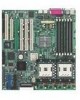
PU-DLS motherboard as pointed out in the picture on page 1-7. 1. SSI-type power connector 2. DDR DIMM sockets 3. Intel® E7501 northbridge 4. Intel power LED 12. SCSI connector 13. ASUS ASIC 14. CPU Power Fail LED 15. LPC Super I/O controller 16. Floppy connector 17. Intel® ICH3-S I/O Hub 18. ATI - Asus PU-DLS | PU-DLS User Manual - Page 21
12 3 4 5 6 21 20 19 22 7 8 9 10 11 18 17 16 15 14 13 12 23 29 28 27 26 25 24 ASUS PU-DLS motherboard user guide 1-7 - Asus PU-DLS | PU-DLS User Manual - Page 22
sockets support up to 12GB system memory using registered ECC PC2100/1600 DDR DIMMs. 3 Intel® E7501 (Plumas 533) MCH. The E7501 Memory Controller Hub (MCH) processor interface supports the System 4Mb firmware hub (FWH) contains the programmable BIOS program. 1-8 Chapter 1: Product introduction - Asus PU-DLS | PU-DLS User Manual - Page 23
of the floppy disk cable. 17 Intel® ICH3-S I/O hub. The I/O supports 8MB display SDRAM for 1280x1024 and true color resolutions. 19 PCI-X/PCI slots. Four 64-bit/100MHz PCI-X slots and two 32-bit/ 33MHz PCI expansion slots support bus master PCI-X/PCI cards. ASUS PU-DLS motherboard user guide - Asus PU-DLS | PU-DLS User Manual - Page 24
100/1000 Mbps data transfer rates. 21 Intel® 82545GC 64-bit PCI-X Gigabit Ethernet controller. This LAN controller is integrated Ethernet LAN component that supports 10/100/1000Mbps data rates. The 82544GC is optimized for LAN on Motherboard (LOM), enterprise networking, and Internet appliances that - Asus PU-DLS | PU-DLS User Manual - Page 25
Chapter 2 This chapter describes the hardware setup procedures that you have to perform when installing system components. It includes details on the switch/jumper settings and connector locations on the motherboard. Hardware information - Asus PU-DLS | PU-DLS User Manual - Page 26
Chapter summary 2.1 Motherboard installation 2-1 2.2 Motherboard layout 2-2 2.3 Before you proceed 2-3 2.4 Central Processing Unit (CPU 2-4 2.5 System memory 2-8 2.6 Expansion slots 2-11 2.7 Jumpers 2-14 2.8 Connectors 2-18 ASUS PU-DLS motherboard - Asus PU-DLS | PU-DLS User Manual - Page 27
indicated in the image below. 2.1.2 Screw holes Place 10 screws into the holes indicated by circles to secure the motherboard to the chassis. Do not overtighten the screws! Doing so may damage the motherboard. Place this side towards the rear of the chassis ASUS PU-DLS motherboard user guide 2-1 - Asus PU-DLS | PU-DLS User Manual - Page 28
2 (u49) Intel® E7501 (Plumas 533) MCH CPU_FAN2 CHASSIS_FAN1 J15 PCI-X4 (64-bit, 100MHz 3V) Intel® P64H2 PCI-X Hub SSI12V J16 J13 PCI-X3 (64-bit, 100MHz 3V) PCI-X2 (64-bit, 100MHz 3V) PCI-X1 (64-bit, 100MHz 3V) PCI2 (32-bit, 33MHz 5V) PCI1 (32-bit, 33MHz 5V) ERMC CON2 VGA RAM J2 - Asus PU-DLS | PU-DLS User Manual - Page 29
sure to install identical CPUs if you wish to use the dual-processor capability. This LED does not light up if you installed only one motherboard component. CPULED1 ® PU-DLS PU-DLS Onboard LED ON CPU Failure OFF CPU OK LED1 ON Standby Power OFF Powered Off ASUS PU-DLS motherboard user guide - Asus PU-DLS | PU-DLS User Manual - Page 30
frequencies, faster execution of integer instructions, and data transfer rate of up to 4.2/3.2GB/s. ® PU-DLS Prestonia Gold Arrow PU-DLS Socket 604 Note in the illustration that the CPU has a gold triangular mark on one corner. This mark indicates the processor Pin 1 that should match a specific - Asus PU-DLS | PU-DLS User Manual - Page 31
CPU in socket 1. Follow these steps to install a CPU. 1. Locate the 604-pin ZIF sockets on the motherboard. Unlock the socket by pressing the lever sideways, then lift it up to at least 115° angle. Make clicks on the side tab to indicate that it is locked. ASUS PU-DLS motherboard user guide 2-5 - Asus PU-DLS | PU-DLS User Manual - Page 32
2.4.3 Installing the CPU heatsink and fan The Intel® Xeon™ processors require specially designed heatsink and fan assembly to ensure optimum thermal condition and performance the plastic retention base. (The retention base comes installed with the motherboard.) 2-6 Chapter 2: Hardware information - Asus PU-DLS | PU-DLS User Manual - Page 33
3. Use a small flat screw driver to attach the other end of motherboard labeled CPUFAN1 (for the CPU on socket 1) and CPUFAN2 (for the CPU on socket 2). Don't forget to connect the CPU fan cable. Hardware monitoring problems may occur if you fail to plug the cable. ASUS PU-DLS motherboard user guide - Asus PU-DLS | PU-DLS User Manual - Page 34
memory 2.5.1 Overview The motherboard comes with six Double Data Rate (DDR) Dual Inline Memory Module (DIMM) sockets. These sockets support up to 12GB system memory using 184-pin registered PC2100/1600 DIMMs with Serial Presence Detect (SPD) and Error Check and Correction (ECC). ® PU-DLS PU-DLS - Asus PU-DLS | PU-DLS User Manual - Page 35
DDR6 - Installed - - Installed Installed * Memory width is 64-bit; low performance ** Memory width is 128-bit; high performance If you use a 128-bit memory width configuration, make sure to install identical (the same type and size) DDR DIMM pairs. ASUS PU-DLS motherboard user guide 2-9 - Asus PU-DLS | PU-DLS User Manual - Page 36
components. Failure to do so may cause severe damage to both the motherboard and the components. Follow these steps to install a DIMM. 1. Unlock outward to unlock the DIMM. 2. Remove the DIMM from the socket. Support the DIMM lightly with your fingers when pressing the retaining clips. The DIMM - Asus PU-DLS | PU-DLS User Manual - Page 37
and the expansion cards that they support. Make sure to unplug the power BIOS settings, if any. See Chapter 4 for information on BIOS setup. 2. Assign an IRQ to the card. Refer to the tables on the next page. 3. Install the software drivers for the expansion card. ASUS PU-DLS motherboard user guide - Asus PU-DLS | PU-DLS User Manual - Page 38
Processor 14* 9 Primary IDE Channel 15* 10 Secondary IDE Channel * These IRQs are usually available for ISA or PCI devices. IRQ assignments for this motherboard PCIX1 slot (supports using PCI cards on shared slots, ensure that the drivers support "Share IRQ" or that the cards do not need - Asus PU-DLS | PU-DLS User Manual - Page 39
device Card installed PCI-X bus speed Channel A Intel 82544GC PCI-X LAN None One (on PCI-X3 133 MHz 100 MHz 66 MHz * PCI-X1 supports a ZCR (Zero Channel RAID) card. See ASUS Server Management Card. The PCI bus speed for these slots is fixed to 33MHz. ASUS PU-DLS motherboard user guide 2-13 - Asus PU-DLS | PU-DLS User Manual - Page 40
operation. 1. CPU external frequency selection (J16) This jumper allows you to select your desired CPU external frequency (or bus clock). ® PU-DLS PU-DLS CPU External Frequency Selection J16 12 CPU speed AUTO detect (Default) 23 100MHz 1 23 133MHz 2. SCSI setting (J13) This jumper allows - Asus PU-DLS | PU-DLS User Manual - Page 41
to pins 1-2 to enable the onboard Intel 82540EM 32-bit Gigabit Ethernet controller and support 10/100/1000 Mbps networking. Set to pins 2-3 to disable the controller. ® PU-DLS J1 12 23 Enable (Default) Disable PU-DLS Intel 82540 LAN Chip Setting ASUS PU-DLS motherboard user guide 2-15 - Asus PU-DLS | PU-DLS User Manual - Page 42
Set this jumper to pins 1-2 to disable the keyboard wake-up feature. Set to pins 2-3 to enable the wake-up feature. ® PU-DLS J14 12 23 Disable (Default) Enable PU-DLS Keyboard WAKE-UP Setting 6. Onboard VGA setting (J2) This jumper allows you to enable or disbale the onboard VGA feature. Set - Asus PU-DLS | PU-DLS User Manual - Page 43
process and enter BIOS setup to re-enter data. Except when clearing the RTC RAM, never remove the cap on CLRTC jumper default position. Removing the cap will cause system boot failure! ® PU-DLS PU-DLS Clear RTC RAM J3 12 23 Clear CMOS Normal (Default) ASUS PU-DLS motherboard user guide 2-17 - Asus PU-DLS | PU-DLS User Manual - Page 44
(34-1 pin FLOPPY1) This connector supports the provided floppy drive ribbon cable. After connecting one end to the motherboard, connect the other end to the floppy drive. (Pin 5 is removed to prevent incorrect insertion when using ribbon cables with pin 5 plug). ® PU-DLS FLOPPY1 PIN 1 NOTE: Orient - Asus PU-DLS | PU-DLS User Manual - Page 45
its jumper accordingly. Refer to the hard disk documentation for the jumper settings. BIOS supports specific device bootup. If you have more than two UltraDMA/100/66 devices, UltraDMA/66 cable included in the motherboard package also supports UltraDMA/100. ASUS PU-DLS motherboard user guide 2-19 - Asus PU-DLS | PU-DLS User Manual - Page 46
In addition to the 24/20-pin SSI/ATXPWR connector (U21), this motherboard requires that you connect the 8/4-pin SSI12V/ATX12V (U58) power plug +5 Volts +5 Volts +5 Volts Ground ® PU-DLS GND GND GND For Power Supply with 4-pin Power Connector PU-DLS SSI/ATX Power Connector U58 (SSI12V/ATX12V) - Asus PU-DLS | PU-DLS User Manual - Page 47
Devices (up to 15 devices) 68-pin Female Terminator 68-pin Internal SCSI Cable (Twisted-Pair Ribbon) Channel A Internal SCSI Devices (up to 15 devices) PU-DLS SCSI Connection Example 68-pin Female Terminator ASUS PU-DLS motherboard user guide 2-21 - Asus PU-DLS | PU-DLS User Manual - Page 48
of sufficient air flow within the system may damage the motherboard components. These are not jumpers! DO NOT place jumper caps on the fan connectors! ® PU-DLS CPU_FAN1 CHASSIS_FAN2 GND +12V Rotation Rotation +12V GND PU-DLS 12-V Fan Connectors Rotation +12V GND CHASSIS_FAN1 CPU_FAN2 GND - Asus PU-DLS | PU-DLS User Manual - Page 49
PU-DLS PU-DLS eRMC Connector 9. IPMI connector (4-pin CON2) The Intelligent Platform Management Interface (IPMI) connector is for the ASMC card. Connect the 4-pin ASMC interface cable to this connector. CON2 PU-DLS IPMI Connector ® PU-DLS NC IPMICLK GND IPMIDATA ASUS PU-DLS motherboard user guide - Asus PU-DLS | PU-DLS User Manual - Page 50
-Channel RAID card or the Intel RAID Controller SRCZCR to provide advanced RAID functionality. The RAID card supports RAID levels 0, 1, 5, multilevel 0/1 and 0/5, cache memory modules with ECC, and predictive caching capability. SMBCLK Ground SMBDATA +3V ® PU-DLS PU-DLS Zero-Channel RAID 2-24 - Asus PU-DLS | PU-DLS User Manual - Page 51
Lock Speaker Power LED Connector +5VSB PLED Keylock Ground +5V Ground Ground Speaker +5 V MLED ExtSMI# Ground PWR Ground Reset Ground PU-DLS System Panel Connectors Message LED SMI Lead Reset SW ATX Power Switch* * Requires an ATX power supply. ASUS PU-DLS motherboard user guide 2-25 - Asus PU-DLS | PU-DLS User Manual - Page 52
system message LED feature requires an ACPI OS and driver support. • System Warning Speaker Lead (4-pin SPEAKER) , or ON and SOFT OFF, depending on the BIOS or OS settings. Pressing the power switch while in mounted suspend switch, and allows you to manually place the system into "Suspend Mode" or - Asus PU-DLS | PU-DLS User Manual - Page 53
Chapter 3 This chapter describes the power up sequence and gives information on the BIOS beep codes. Powering up - Asus PU-DLS | PU-DLS User Manual - Page 54
Chapter summary 3.1 Starting up for the first time 3-1 3.2 Powering off the computer 3-2 ASUS PU-DLS motherboard - Asus PU-DLS | PU-DLS User Manual - Page 55
or call your retailer for assistance. Award BIOS Beep Codes Beep One short beep when displaying memory bad CPU overheated; System running at a lower frequency 7. At power on, hold down to enter BIOS Setup. Follow the instructions in Chapter 4. ASUS PU-DLS motherboard user guide - Asus PU-DLS | PU-DLS User Manual - Page 56
3.2 Powering off the computer You must first exit the operating system and shut down the system before switching off the power. For ATX power supplies, you can press the ATX power switch after exiting or shutting down the operating system. If you use Windows 2000/XP, click the Start button, click - Asus PU-DLS | PU-DLS User Manual - Page 57
Chapter 4 This chapter tells how to change system settings through the BIOS Setup menus. Detailed descriptions of the BIOS parameters are also provided. BIOS setup - Asus PU-DLS | PU-DLS User Manual - Page 58
Chapter summary 4.1 Managing and updating your BIOS 4-1 4.2 BIOS Setup program 4-5 4.3 Main Menu 4-8 4.4 Advanced Menu 4-15 4.5 Power Menu 4-23 4.6 Boot Menu 4-28 4.7 Server Menu 4-30 4.8 Exit Menu 4-31 ASUS PU-DLS motherboard - Asus PU-DLS | PU-DLS User Manual - Page 59
within Windows, and does not work with certain memory drivers that may be loaded when you boot from the Memory:, the memory chip is either not programmable or is not supported by the ACPI BIOS and therefore, cannot be programmed by the Flash Memory Writer utility. ASUS PU-DLS motherboard user guide - Asus PU-DLS | PU-DLS User Manual - Page 60
5. Select 1. Save Current BIOS to File from the Main menu and press . The Save Current BIOS To File screen appears. 6. Type a filename and the path, for example, A:\XXX-XX.XXX, then press . 4-2 Chapter 4: BIOS Setup - Asus PU-DLS | PU-DLS User Manual - Page 61
Boot Block and ESCD screen appears. 5. Type the filename of your new BIOS and the path, for example, A:\XXX-XX.XXX, then press . To cancel this operation, press . 6. When prompted to confirm the BIOS update, press Y to start the update. ASUS PU-DLS motherboard user guide 4-3 - Asus PU-DLS | PU-DLS User Manual - Page 62
process, and if the problem persists, load the original BIOS file you saved to the boot disk. If the Flash Memory Writer utility is not able to successfully update a complete BIOS file, the system may not boot. If this happens, call the ASUS service center for support. 4-4 Chapter 4: BIOS Setup - Asus PU-DLS | PU-DLS User Manual - Page 63
-menus and make your selections among the predetermined choices. Because the BIOS software is constantly being updated, the following BIOS setup screens and descriptions are for reference purposes only, and may not exactly match what you see on your screen. ASUS PU-DLS motherboard user guide 4-5 - Asus PU-DLS | PU-DLS User Manual - Page 64
system device used to locate and load the Operating System. SERVER Use this menu to set server-related items EXIT Use this menu to exit the current menu > or Displays the General Help screen from anywhere in the BIOS Setup Jumps to the Exit menu or returns to the main menu from - Asus PU-DLS | PU-DLS User Manual - Page 65
General help In addition to the Item Specific Help window, the BIOS setup program also provides a General Help screen. You may launch this screen from any menu by simply each menu. This window displays the help text for the currently highlighted field. ASUS PU-DLS motherboard user guide 4-7 - Asus PU-DLS | PU-DLS User Manual - Page 66
. Configuration options: [None] [360K, 5.25 in.] [1.2M , 5.25 in.] [720K , 3.5 in.] [1.44M, 3.5 in.] [2.88M, 3.5 in.] Floppy 3 Mode Support [Disabled] This is required to support older Japanese floppy drives. The Floppy 3 Mode feature allows reading and writing of 1.2MB (as opposed to 1.44MB) on - Asus PU-DLS | PU-DLS User Manual - Page 67
to halt. Configuration options: [All Errors] [No Error] [All but Keyboard] [All but Disk] [All but Disk/Keyboard] Installed Memory [XXX MB] This field automatically displays the amount of conventional memory detected by the system during the boot process. ASUS PU-DLS motherboard user guide 4-9 - Asus PU-DLS | PU-DLS User Manual - Page 68
already formatted on an older system, Setup may detect incorrect parameters. In these cases, select [User Type HDD] to manually enter the IDE hard disk drive parameters. Refer to the next section for details. Before attempting fail to recognize the installed hard disk. 4-10 Chapter 4: BIOS Setup - Asus PU-DLS | PU-DLS User Manual - Page 69
User Type HDD] Manually enter the number of cylinders, heads and sectors per track for the drive. Refer to the drive documentation or on the drive label for this information. After entering the IDE hard disk drive information into BIOS that you configured. ASUS PU-DLS motherboard user guide 4-11 - Asus PU-DLS | PU-DLS User Manual - Page 70
value. To make changes to this field, set the Type field to [User Type HDD] and the Translation Method field to [Manual]. CHS Capacity This field shows the drive's maximum CHS capacity as calculated by the BIOS based on the drive information you entered. Maximum LBA Capacity This field shows - Asus PU-DLS | PU-DLS User Manual - Page 71
data integrity for compatible IDE devices. Set to [Disabled] to suppress Ultra DMA capability. To make changes to this field, set the Type field to [User Type HDD]. Configuration options: [0] [1] [2] [3] [4] [5] [Disabled] ASUS PU-DLS motherboard user guide 4-13 - Asus PU-DLS | PU-DLS User Manual - Page 72
4.3.2 Keyboard Features Boot Up NumLock Status [On] This field enables users to activate the Number Lock function upon system boot. Configuration options: [Off] [On] displaying the first and second characters. Configuration options: [1/4 Sec] [1/2 Sec] [3/4 Sec] [1 Sec] 4-14 Chapter 4: BIOS Setup - Asus PU-DLS | PU-DLS User Manual - Page 73
Update [Enabled] This field functions as an update loader integrated into the BIOS to supply the processor with the required data. When set to [Enabled], the BIOS loads the update on all processors during system bootup. Configuration options: [Disabled] [Enabled] ASUS PU-DLS motherboard user guide - Asus PU-DLS | PU-DLS User Manual - Page 74
Memory > 64M [Disabled] When using OS/2 operating systems with installed DRAM of greater than 64MB, you need to set this option to [Enabled]. Otherwise, leave to the default setting [Disabled]. Configuration options: [Disabled] [Enabled] USB Legacy Support [Auto] This motherboard supports Universal - Asus PU-DLS | PU-DLS User Manual - Page 75
By SPD] This parameter allows you to set the optimal timings for items 2-5, depending on the memory modules that you are using. The default setting is [By SPD], which configures items 2-5 by recommended to keep the default setting for stable system operation. ASUS PU-DLS motherboard user guide 4-17 - Asus PU-DLS | PU-DLS User Manual - Page 76
the video memory of the processor. It can greatly improve the display speed by caching the display data. You must set this to UC (uncacheable) if your display card does not support this feature, [Disabled]. Configuration options: [Both] [Primary] [Secondary] [Disabled] 4-18 Chapter 4: BIOS Setup - Asus PU-DLS | PU-DLS User Manual - Page 77
connector. If you disable this field, the Parallel Port Mode and ECP DMA Select configurations are not available. Configuration options: [Disabled] [378H/IRQ7] [278H/IRQ5] ASUS PU-DLS motherboard user guide 4-19 - Asus PU-DLS | PU-DLS User Manual - Page 78
PCI slot 1and PCI slot 2. Slots 3/4/5/6/7/8 map to PCIX1/2/3/4, with PCIX4 serving riser slots A/B/C. Configuration options: [Auto] [NA] [3] [4] [5] [7] [9] [10] [11] [12] [14] [15] 4-20 Chapter 4: BIOS Setup - Asus PU-DLS | PU-DLS User Manual - Page 79
Controllers] ONB Intel 82544 LAN Boot ROM [Disabled] ONB Intel 82540 LAN Boot ROM [Disabled] When set to [Enabled], these fields allow the system to boot from the network using the onboard LAN controller boot ROM. Configuration options: [Disabled] [Enabled] ASUS PU-DLS motherboard user guide 4-21 - Asus PU-DLS | PU-DLS User Manual - Page 80
to [Yes] if you install a legacy ISA card that requires a unique IRQ and you are NOT using ICU. Configuration options: [No/ICU] [Yes] 4-22 Chapter 4: BIOS Setup - Asus PU-DLS | PU-DLS User Manual - Page 81
Max Saving] You should install the Advanced Power Management (APM) utility to keep the system time updated even when the computer enters suspend mode. In Windows 3.x and Windows 95, you need to item "Advanced" in the Power Management Properties dialog box. ASUS PU-DLS motherboard user guide 4-23 - Asus PU-DLS | PU-DLS User Manual - Page 82
Management System (DPMS) feature allows the BIOS to control the video display card if it supports the DPMS feature. [Blank Screen] only disk drives in the system after a period of inactivity as set in this user-configurable field. This feature does not affect SCSI hard drives. Configuration options: - Asus PU-DLS | PU-DLS User Manual - Page 83
a PCI LAN or modem card. This feature requires an ATX power supply that provides at least 1A on the +5VSB lead. Configuration options: [Disabled] [Enabled] ASUS PU-DLS motherboard user guide 4-25 - Asus PU-DLS | PU-DLS User Manual - Page 84
time of the day by selecting [Everyday] or at a certain time and day by selecting [By Date]. Configuration options: [Disabled] [Everyday] [By Date] 4-26 Chapter 4: BIOS Setup - Asus PU-DLS | PU-DLS User Manual - Page 85
[xxxC/xxxF] CPU1 Temperature [xxxC/xxxF] The onboard hardware monitor is able to detect the MB (motherboard) and CPU temperatures. Set to [Ignore] only if necessary. CPU0 Fan Speed [xxxxRPM] CPU1 Fan prompted to "Press F1 to continue or DEL to enter SETUP". ASUS PU-DLS motherboard user guide 4-27 - Asus PU-DLS | PU-DLS User Manual - Page 86
4.6 Boot Menu The motherboard BIOS supports the BIOS Boot Specification (BBS) version 1.01. BBS is an intelligent from. A BAID is any device that can boot on an operating system but requires a specific BIOS code for support. Bootable FDDs, ATA HDD, ATAPI CD-ROM, ATA ZIP, and ATA MO drives are - Asus PU-DLS | PU-DLS User Manual - Page 87
motherboard, the following options are present onboard: [ Intel Corporation IBA 4.0.22 Slo (LAN A)] [ Intel instead of using the BIOS. When [Yes] is Support [Enabled] This field allows you to enable or disable the MultiProcessor Specification 1.4 support ASUS PU-DLS motherboard user guide 4-29 - Asus PU-DLS | PU-DLS User Manual - Page 88
40 or 80 tracks. Configuration options: [Disabled] [Enabled] 4.7 Server Menu Remote Console [Disabled] This field allows the text mode VGA display to be sent out to VT100 terminal through COM1. This function is effective at BIOS POST and DOS environment. Configuration options: [Disabled] [Enabled - Asus PU-DLS | PU-DLS User Manual - Page 89
from the Exit menu to ensure the values you selected are saved to the CMOS RAM. The CMOS RAM is sustained by an onboard backup battery and stays on even when the PC is turned date, system time, and password, the BIOS asks for a confirmation before exiting. ASUS PU-DLS motherboard user guide 4-31 - Asus PU-DLS | PU-DLS User Manual - Page 90
. Select Exit Saving Changes or make other changes before saving the values to the non-volatile RAM. Discard Changes This option allows you to discard the selections you made and restore the previously appears. Select [Yes] to save any changes to the non-volatile RAM. 4-32 Chapter 4: BIOS Setup - Asus PU-DLS | PU-DLS User Manual - Page 91
Chapter 5 This chapter tells how to install SCSI, LAN, and VGA drivers for various operating systems. Driver installation - Asus PU-DLS | PU-DLS User Manual - Page 92
Chapter summary 5.1 Support CD contents 5-1 5.2 Microsoft Windows NT Server 4.0 5-3 5.3 Microsoft Windows 2000 Server 5-12 5.4 Microsoft Windows XP Professional .......... 5-22 5.5 Novell NetWare Server 5-31 5.6 SCO Open Server 5.0.6 5-39 5.7 Linux RedHat 8.0 5-41 ASUS PU-DLS motherboard - Asus PU-DLS | PU-DLS User Manual - Page 93
displays the drivers available for the onboard devices. Follow the installation wizards or find additional instructions as text files in each of the driver folders. 5.1.2 Management Sofware This screen displays the ASUS proprietary server management software. ASUS PU-DLS motherboard user guide 5-1 - Asus PU-DLS | PU-DLS User Manual - Page 94
5.1.3 Utilities This screen displays the available system utilities that you can install. 5.1.4 Contact This screen displays the ASUS worldwide contact information. 5-2 Chapter 5: Driver installation - Asus PU-DLS | PU-DLS User Manual - Page 95
the menu to display the folders and sub-folders in the support CD. 4. Copy the entire winnt40 folder and the txtsetup.oem file from the support CD into the root directory of the floppy disk. These items are in the following folder path: \drivers\adaptec\7902\ ASUS PU-DLS motherboard user guide 5-3 - Asus PU-DLS | PU-DLS User Manual - Page 96
S to specify an additional device. 5. Press Enter to select Other; insert the Adaptec Ultra320 FMS driver disk in your floppy disk drive and press Enter. 6. The screen displays the adapter drivers supported on the disk. Select Adaptec Ultra320 SCSI Cards (WinNT 4.0) and press Enter. 7. If you want - Asus PU-DLS | PU-DLS User Manual - Page 97
. 2. Start Windows NT 4.0 and install the driver from the Adaptec Ultra320 driver disk. 3. Shut down Windows NT 4.0 and turn off your system. 4. Switch the bootable hard drive from the old SCSI controller to the Ultra320 controller. 5. Power on your system. ASUS PU-DLS motherboard user guide 5-5 - Asus PU-DLS | PU-DLS User Manual - Page 98
Microsoft® Windows® NT Server 4.0 (continued) 5.2.2 Intel® 82544GC/82540EM LAN driver installation It is recommended that you use the Intel 82544GC/82540EM LAN drivers from the support CD. A. Preparing the Intel 82544GC/82540EM LAN driver disk Prepare one blank formatted high density floppy disk - Asus PU-DLS | PU-DLS User Manual - Page 99
5. Follow the succeeding installation instructions. 6. When done, the following screen appears. Click Finish to complete the installation. ASUS PU-DLS motherboard user guide 5-7 - Asus PU-DLS | PU-DLS User Manual - Page 100
Microsoft® Windows® NT Server 4.0 (continued) B. New System Installation 1. When the Installing Windows NT Networking screen appears, press Next to display the . 3. On the screen that appears, click the button Select from list... to dispaly the following. 5-8 Chapter 5: Driver installation - Asus PU-DLS | PU-DLS User Manual - Page 101
Adapter, then click OK. Follow the succeeding screen instructions. 7. When done, the following screen appears showing the Intel(R) PRO/1000 Family Adapter in the list. 8. Click Next and follow any other screen instructions to complete the installation. ASUS PU-DLS motherboard user guide 5-9 - Asus PU-DLS | PU-DLS User Manual - Page 102
select an adapter from the list. Instead, insert the LAN driver disk that you created from the Support CD. Refer to the section "A. Preparing the Intel 82544GC/82540EM LAN Driver Disk" if you have not yet created the LAN driver disk. 5. Follow steps 4 to 8 in section "B. New System Installation" to - Asus PU-DLS | PU-DLS User Manual - Page 103
, the following screen appears. Click on ATI Rage XL Display Driver to install the driver. If Autorun is disabled, install the display driver from the following path: \Drivers\Ati\Nt40\Setup.exe 3. Follow the screen instructions to complete the installation. ASUS PU-DLS motherboard user guide 5-11 - Asus PU-DLS | PU-DLS User Manual - Page 104
on the 2ksetup.exe file under the folder path: \drivers\adaptec\7902\win2000\ 5. Follow the succeeding screen instructions to complete the process. A3. Manually 1. Insert a blank formatted high-density floppy disk into the floppy drive. 2. Place the support CD into the CD-ROM drive. 3. Click on the - Asus PU-DLS | PU-DLS User Manual - Page 105
sure Bootable CD-ROM support is enabled. This is done through the System BIOS Setup Utility. 2. driver disk in your disk drive and enter the following path, then click OK. \win2000 5. Select the Adaptec Ultra320 driver from the list, then click the Next button. ASUS PU-DLS motherboard user guide - Asus PU-DLS | PU-DLS User Manual - Page 106
Microsoft® Windows® 2000 Server (continued) 6. Click the Next button again to confirm the installation of the driver. You may be to restart the computer. Select Yes. D. Updating the Adaptec Ultra320 driver under Windows 2000 Follow these instructions only if Windows 2000 is already installed. 1. - Asus PU-DLS | PU-DLS User Manual - Page 107
up the operating system. Install the driver for the Adaptec Ultra320 Adapter. 3. Shut down Windows 2000. Turn off your system if necessary. 4. Switch the bootable hard drive from the old SCSI controller to the Ultra320 controller and boot up your computer. ASUS PU-DLS motherboard user guide 5-15 - Asus PU-DLS | PU-DLS User Manual - Page 108
Microsoft® Windows® 2000 Server (continued) 5.3.2 Intel® 82544GC/82540EM LAN driver installation It is recommended that you use the Intel 82544GC/82540EM LAN drivers from the support CD. A. Preparing the Intel 82544GC/82540EM LAN driver disk Prepare one blank formatted high density floppy disk - Asus PU-DLS | PU-DLS User Manual - Page 109
5. Follow the succeeding installation instructions. 6. When done, the following screen appears. Click Finish to complete the installation. ASUS PU-DLS motherboard user guide 5-17 - Asus PU-DLS | PU-DLS User Manual - Page 110
You may update the LAN driver directly from the support CD. 1. Insert the support CD into the CD-ROM drive. On the screen that appears, click on Intel PRO/1000 LAN Driver, then on the item Install Base Driver Only. 2. Follow the screen instructions to complete the driver update. When done - Asus PU-DLS | PU-DLS User Manual - Page 111
the Intel(R) 82554GC-based Network Connection, click the right mouse button, and select Properties to display the following. 4. Highlight the Intel(R) PRO-1000 Server Adapter, click the right mouse button, and select Properties to display the following. ASUS PU-DLS motherboard user guide 5-19 - Asus PU-DLS | PU-DLS User Manual - Page 112
® Windows® 2000 Server (continued) C. Updating the LAN driver using the LAN driver disk You may also update the LAN drivers from the LAN Driver Disk if you created one in section "A. Preparing the Intel 82544GC/82540EM LAN Driver Disk." Follow these steps to update from the LAN driver disk. 1. Boot - Asus PU-DLS | PU-DLS User Manual - Page 113
. You do not need to load any driver for supporting the onboard ATI RAGE XL graphics controller chipset. 5.3.4 Enabling ATA100 Feature in Windows® 2000 To enable the ATA100 feature under Windows 2000, you need to upgrade to Windows 2000 Service Pack 2. ASUS PU-DLS motherboard user guide 5-21 - Asus PU-DLS | PU-DLS User Manual - Page 114
menu to display the folders and sub-folders in the support CD. 4. Double-click on the xpsetup.exe file under the folder path: \drivers\adaptec\7902\winxp\ 5. Follow the succeeding screen instructions to complete the process. A3. Manually 1. Insert a blank formatted high-density floppy disk into the - Asus PU-DLS | PU-DLS User Manual - Page 115
CD-ROM, make sure Bootable CD-ROM support is enabled. This is done through the System BIOS Setup Utility. 2. Press F6 when this and then continue. 5. The screen displays the adapter drivers supported on the disk. Select Adaptec Ultra320 SCSI Cards (WinXP ASUS PU-DLS motherboard user guide 5-23 - Asus PU-DLS | PU-DLS User Manual - Page 116
drive A, and then continue. 5. The screen displays the adapter drivers supported on the disk. Select Adaptec Ultra320 SCSI Cards (WinXP IA64) setting up the operating system. D. Updating the Adaptec Ultra320 driver under Windows XP Follow these instructions only if Windows XP is already installed - Asus PU-DLS | PU-DLS User Manual - Page 117
On the screen that appears, select Create Install Disk. 3. The next screen allows you to select an operating system to install the driver. Select Windows XP. 4. Select A:/ for the destination drive, then click on Create Disk. (See picture on the next page.) ASUS PU-DLS motherboard user guide 5-25 - Asus PU-DLS | PU-DLS User Manual - Page 118
Microsoft® Windows® XP Professional (continued) 5. Follow the succeeding installation instructions. 6. When done, the following screen appears. Click Finish to complete the installation. 5-26 Chapter 5: Driver installation - Asus PU-DLS | PU-DLS User Manual - Page 119
drive. On the screen that appears, click on Intel PRO/1000 LAN Driver, then on the item Install Base Driver Only. 2. Follow the screen instructions to complete the driver update. When done, your Computer Management window shows the installed LAN adapters. ASUS PU-DLS motherboard user guide 5-27 - Asus PU-DLS | PU-DLS User Manual - Page 120
the Intel(R) 82554GC-based Network Connection, click the right mouse button, and select Properties to display the following. 4. Highlight the Intel(R) PRO-1000 Server Adapter, click the right mouse button, and select Properties to display the following. 5-28 Chapter 5: Driver installation - Asus PU-DLS | PU-DLS User Manual - Page 121
Next. Select Display a list of the known drivers for this device ... 8. Select Network adapters under Hardware Type, and click Next. 9. Click Have Disk..., then insert the LAN driver disk. 10. Follow the succeeding instructions to complete the installation. ASUS PU-DLS motherboard user guide 5-29 - Asus PU-DLS | PU-DLS User Manual - Page 122
(continued) 5.4.3 ATI® Rage XL Display Driver Installation Windows XP system can automatically recognize the ATI RAGE XL PCI driver during system installation. You do not need to load any driver for supporting the onboard ATI RAGE XL graphics controller chipset. 5-30 Chapter 5: Driver installation - Asus PU-DLS | PU-DLS User Manual - Page 123
NETWARE\V42_V50\ 8. Select ADPU320.HAM and press ENTER. 9. Select "Return to driver list" to accept the default slot number, and press ENTER. 10. Press ESC, select "Return to driver summary" and press ENTER. 11. Press ESC, select "Continue" and press ENTER. ASUS PU-DLS motherboard user guide 5-31 - Asus PU-DLS | PU-DLS User Manual - Page 124
an Ultra320 SCSI Controller 1. Begin installation of NetWare on your server as instructed in your NetWare documentation. 2. When the screen "Choose the Server Drivers - Summary" appears, select "Select additional or modify selected Disk/LAN drivers" and press ENTER. 3. Highlight "Disk and CD-ROM - Asus PU-DLS | PU-DLS User Manual - Page 125
file. 13. Choose "Select/Modify driver parameters" and press ENTER. 14. Press Alt-Esc to switch to System Console, and at the prompt, type: LOAD A:\NETWARE\V51_V60\ADPU320.HAM (for NetWare 5.1/6.0) or LOAD A:\NETWARE\V42_V50\ADPU320.HAM (for NetWare 5.0) ASUS PU-DLS motherboard user guide 5-33 - Asus PU-DLS | PU-DLS User Manual - Page 126
Novell® Netware® Server (continued) 15. Write down the HIN value displayed on the the path to the ADPU320.HAM driver: A:\NETWARE\V42_V50\ 8. Select ADPU320.HAM and press ENTER. 9. When prompted, click 'Yes' to copy the driver. 10. Specify the path where the driver ADPU320.HAM should be installed, or - Asus PU-DLS | PU-DLS User Manual - Page 127
)". 3. Select "Edit STARTUP.NCF file". 4. Remove the line(s) for loading ADPU320.HAM driver. 5. When finished, press F10 to save and exit. 6. Press ESC twice to quit NWCONFIG utility. NOTE A DOS text editor can also be used to modify the STARTUP.NCF file. ASUS PU-DLS motherboard user guide 5-35 - Asus PU-DLS | PU-DLS User Manual - Page 128
Novell® Netware® Server (continued) 5.5.2 Intel® 82544GC/82540EM LAN driver installation It is recommended that you use the Intel 82544GC/82540EM LAN drivers from the support CD. A. Preparing the Intel 82544GC/82540EM LAN driver disk Prepare one blank formatted high density floppy disk before - Asus PU-DLS | PU-DLS User Manual - Page 129
5. Follow the succeeding installation instructions. 6. When done, the following screen appears. Click Finish to complete the installation. ASUS PU-DLS motherboard user guide 5-37 - Asus PU-DLS | PU-DLS User Manual - Page 130
5.x/6.0 Installations 1. Prepare the Intel(R) PRO/1000 Server Adapter driver from the previous section. 2. Install NetWare 4.2 according to the NetWare instructions. 3. When the NetWare installation procedure prompts you for a Network Driver, insert the Intel PRO/1000 driver disk into drive A: Then - Asus PU-DLS | PU-DLS User Manual - Page 131
the network driver for the onboard LAN device. User also can find the Intel 82544GC/82540EM Network driver from the support CD at: \Drivers\Lan\openunix\ A. Installing the eeE Driver for SCO OpenServer system.At the command prompt, type: # reboot (or init 6) ASUS PU-DLS motherboard user guide 5-39 - Asus PU-DLS | PU-DLS User Manual - Page 132
SCO Open Server 5.0.6 (continued) 5.6.2 ATI® Rage XL Display Driver Installation SCO OpenServer 5.0.6 system can correctly recognize ATI Rage XL graphic controller (ATI RAGE PRO/LT-PRO/XL/Mobility (P/M/M1)) during installation. User doesn't need to load or modify the video driver for the onboard VGA - Asus PU-DLS | PU-DLS User Manual - Page 133
the driver. For questions related to hardware requirements, refer to the documentation supplied with your Intel PRO/1000 adapter. All hardware requirements listed apply to use with Linux. New features include support for the Intel PRO/1000 desktop adapter. ASUS PU-DLS motherboard user guide 5-41 - Asus PU-DLS | PU-DLS User Manual - Page 134
Updating Driver on an Existing System Installation To build a binary RPM* package of this driver, run 'rpm -tb ' Replace with the specific file name of the driver. 1. Move the base driver now. 5.7.3 ATI® Rage XL Display Driver Installation The RedHat 8.0 system can
-
 1
1 -
 2
2 -
 3
3 -
 4
4 -
 5
5 -
 6
6 -
 7
7 -
8
-
9
-
10
-
11
-
12
-
13
-
14
-
15
-
16
-
17
-
18
-
19
-
20
-
21
-
22
-
23
-
24
-
25
-
26
-
27
-
28
-
29
-
30
-
31
-
32
-
33
-
34
-
35
-
36
-
37
-
38
-
39
-
40
-
41
-
42
-
43
-
44
-
45
-
46
-
47
-
48
-
49
-
50
-
51
-
52
-
53
-
54
-
55
-
56
-
57
-
58
-
59
-
60
-
61
-
62
-
63
-
64
-
65
-
66
-
67
-
68
-
69
-
70
-
71
-
72
-
73
-
74
-
75
-
76
-
77
-
78
-
79
-
80
-
81
-
82
-
83
-
84
-
85
-
86
-
87
-
88
-
89
-
90
-
91
-
92
-
93
-
94
-
95
-
96
-
97
-
98
-
99
-
100
-
101
-
102
-
103
-
104
-
105
-
106
-
107
-
108
-
109
-
110
-
111
-
112
-
113
-
114
-
115
-
116
-
117
-
118
-
119
-
120
-
121
-
122
-
123
-
124
-
125
-
126
-
127
-
128
-
129
-
130
-
131
-
132
-
133
-
134
 |
 |

Motherboard
PU-DLS
User Guide